Note: Descriptions are shown in the official language in which they were submitted.
CA 02705001 2014-11-25
63189-747
=
RESEALABLE BEVERAGE CAN END
AND METHODS RELATING TO SAME
[001]
FIELD OF TECHNOLOGY
[002] The present invention relates to packaging for beverages and, more
particularly, to a resealable beverage can end, a resealable closure, and
methods relating
to same.
BACKGROUND
[003] = The structure and functionality of commercial beverage cans have
been
optimizcd over the years. Yet commercial beverage cans have the drawback of
being
unable to reclose after initial opening. Reclosing beverage cans is made more
difficult
by the dissolved carbon dioxide or other gases in a carbonated beverage that
leaves the
solution and tends to increase the pressure in the headspace. Several
resealable can end
dcsigns have been proposed by thc prior art, but none have reached commercial
acceptance.
[004] = Consumers of beverages in plastic bottles, on the other hand, often
reseal
the bottle by screwing its threaded closure onto the bottle finish. This
attribute appeals
to consumers.
[005] Accordingly, there is a need for a resealable beverage can that is
easy or
intuitive to use, has a viable cost, and is not overly complex.
1
CA 02705001 2014-11-25
63189-747
[006] Furthermore, conventional beverage cans are designed to vent the
excess
pressure in the can upon initial opening. Ends used for such beverage cans
have a score line
defining an aperture from which the contents of the can may be dispensed and a
smaller score
line defining a vent. As the tab is lifted, first the vent score severs,
allowing release of the
gasses that have built up in the headspace of the beverage can, and then the
aperture score
ruptures, to define an aperture through which the contents of the beverage can
may be
dispensed. Thus, a user simply lifts the tab to effect both venting and
thereafter opening of
the beverage can.
[007] The opening device described in WO 2007/128810 assigned to Crown
Packaging Technology, Inc. describes an embodiment in which the tab includes a
pin, which
engages in a vent hole in the end panel. A disadvantage of this arrangement is
that upon re-
closing of the device, a user must manually reinsert the pin into the vent
hole to reseal the can
end to prevent leaks and maintain carbonation (if any) of the product inside
the container to
which the opening device is applied.
SUMMARY
[008] Benefits of a recloseable beverage can end may include the ability to
store a
portion of the beverage for later use, security, cleanliness, and maintenance
of the carbonation
level of the beverage even if the beverage is intended to be consumed in one
sitting. This may
require confidence of the user that the beverage can has been properly re-
closed, to maintain
the carbonation level of the beverage, and to provide security against spills
if the re-closed
beverage can is placed in a bag, for example. However, ease of opening the
beverage can, if
the beverage is intended to be consumed in one sitting, should be retained.
[009] Accordingly, a re-sealable can end/beverage can is provided that
provides one
or more of the above identified advantages. In one embodiment, there is
provided a can end
combination comprising a metal can end and resealable closure coupled to the
can end, the
can end comprising a peripheral wall and a center panel, the center panel
including an upper
surface, an opposing lower surface, and an aperture formed therethrough; the
closure
comprising a base plate and a top plate coupled to the base plate at a first
location, the base
2
CA 02705001 2014-11-25
63189-747
plate including a bead, the closure having (i) a sealed position in which at
least one of the base
plate and top plate contact the center panel about the aperture to form a
seal, (ii) an
intermediate position in which the closure is proximate the aperture but not
sealed, and (iii) a
fully open position in which the aperture is exposed to enable pouring liquid
through the
aperture; the base plate being downwardly moveable relative to the top plate
when moved
from the sealed position to the intermediate position; the base plate and top
plate being: (i)
translatable together relative to the can end from the intermediate position
to the fully open
position and (ii) translatable together relative to the can end from the fully
open position to the
intermediate position; the base plate being upwardly moveable into engagement
with the
center panel from the intermediate position into a resealed position forming
at least one of a
bore seal and a flange seal; wherein the bead is configured to engage with a
rim of the
aperture when the base plate is moved into the resealed position to thereby
provide an audible
"click."
[009a] In another aspect there is provided a resealable can end
combination
comprising: a can end having a peripheral wall and a center panel with an
aperture defined
therethrough, and a closure having a base plate and a top plate coupled to the
base plate,
wherein the base plate is moveable in relation to the can end, the closure
having a closed
position, in which at least part of the closure seals the aperture, a venting
position in which
one or more vent pathways extending through a vent hole in the base plate are
opened, and a
fully open position in which the aperture is exposed to enable pouring liquid
through the
aperture; the closure comprising a plug adapted to seal the one or more vent
pathways when
the closure is in its closed position, and a biasing member adapted to bias
the plug towards its
sealed position, wherein the base plate and top plate are: (i) translatable
together relative to
the can end from the venting position to the fully open position; and (ii)
translatable together
relative to the can end from the fully open position to the venting position.
[0091)] In yet another aspect there is provided a resealable beverage
can comprising: a
can body; and a can end combination seamed onto the can body, the can end
combination
comprising a metal can end and resealable closure coupled to the metal can
end, the metal can
end comprising a peripheral wall and a center panel, the center panel
including an upper
surface, an opposing lower surface, and an aperture formed therethrough; the
center panel
3
= CA 02705001 2014-11-25
63189-747
defining a plane; the resealable closure comprising a base plate, a top plate
and a plug,
wherein the base plate is moveable in relation to the can end and the plug
defines at least one
window, wherein the closure has (i) a sealed position in which the plug seals
a vent aperture
that extends through the base plate, (ii) an intermediate position in which
the windows form
vent pathways between headspace of the beverage can and the external
environment, and (iii)
a fully open position in which the aperture is exposed to enable pouring
liquid through the
aperture.
[009c] In a further aspect there is provided a resealable can end
combination for a
= beverage can comprising: a metal can end comprising a peripheral wall and
a center panel, the
center panel including an upper surface, an opposing lower surface, and an
aperture formed
therethrough; a resealable closure coupled to the metal can end, the
resealable closure
comprising a base plate, a top plate, and a plug, wherein the base plate is
moveable in relation
to the can end; a lever arm configured to push the plug downwardly to form the
vent pathways
when a tab on the top plate is lifted, and wherein the closure has (i) a
sealed position in which
the plug seals a vent aperture that extends through the base plate, (ii) an
intermediate position
in which vent pathways extend between headspace of the beverage can and the
external
environment, and (iii) a fully open position in which the aperture is exposed
to enable pouring
liquid through the aperture.
BRIEF DESCRIPTION OF THE FIGURES
[0010] The present technology provides a re-closeable end for a beverage
can and
related methods for making and using the re-closeable end. The technology will
now be
described in more detail, by way of example only, with reference to the
accompanying
drawings, in which:
[0011] Fig. lA is a perspective view of a combination can end and a
resealable closure
illustrating a first embodiment in the fully closed position;
[0012] Fig. 1B is a perspective view of the first embodiment in an
intermediate
position;
3a
CA 02705001 2014-11-25
63189-747
[0013] Fig. 1C is a perspective view of the first embodiment in the fully
open
position;
[0014] Fig. 2A is a cross sectional view of the first embodiment in its
fully closed
position;
[0015] Fig. 2B is an enlarged view of a portion of Fig. 2A depicting a
sealing portion
of the cnd; -
[0016] Fig. 2C is a cross sectional view of an alternative embodiment of
thc can end
in it's fully closed position viewed orthogonal to the tab;
[0017] Fig. 2D is a cross sectional view of the first embodiment of the
can end in it's
intermediate position;
[0018] Fig. 2E is a cross sectional view of the first embodiment in its
fully open
position;
= 3b
CA 02705001 2010-05-05
WO 2009/062004 PCT/US2008/082753
[0019] Fig. 3A is a top perspective view of the top plate of the closure
of the first
embodiment in its pre-assembled state;
[0020] Fig. 3B is a bottom perspective view of the top plate of the first
embodiment
in its pre-assembled state;
[0021] Fig. 4A is a top perspective view of the top plate showing an
alternative tab
configuration;
[0022] Fig. 4B is a bottom perspective view of the top plate showing an
alternative
tab configuration;
[0023] Fig. 5A is a top perspective view of an alternative configuration
of the top
plate of the closure of the first embodiment in its pre-assembled state;
[0024] Fig. 5B is a bottom perspective view of the top plate shown in
Fig. 5A;
[0025] Fig. 6 is a perspective view of a base plate of the first
embodiment in its pre-
assembled state;
[0026] Fig. 7 is a perspective view of an alternative configuration of
the base plate
corresponding to the top plate illustrated in Figs. 5A and 5B;
[0027] Fig. 8A is a perspective view of a base plate having vent slots;
[0028] Fig. 8B is a perspective view of an alternative top late
arrangement suitable
for use with the base plate shown in Fig. 8A having vent slots which allow air
between
the top plate and the base plate;
[0029] Fig. 8C is an isometric view of the closures shown in Figs. 8A and
8B when
assembled onto a can end/body, illustrating vent arches in the assembled
closure to
enable air to enter the closure, when the top plate and base plate are
arranged in a
venting position;
[0030] Fig. 9A is a cross sectional view of a an alternative closure
assembled onto a
can end/body in an unopened position;
[0031] Fig. 9B is a cross sectional view of the closure shown in Fig. 9A
upon
reclosing the can with the tab lifted to reengage the bore seal and face seal;
[0032] Fig. 10A is a top view of a first alternative top plate
configuration, in a closed
position, that may be employed with first embodiment closure;
[0033] Fig. 10B is a perspective view of the top plate configuration
shown in Fig.
10A showing the closure in an intermediate position;
4
CA 02705001 2010-05-05
WO 2009/062004 PCT/US2008/082753
[0034] Fig. 11A is a top view of a second alternative top plate
configuration, in a
closed position, that may be employed with first embodiment closure;
[0035] Fig. 11B is a perspective view of the top plate configuration
shown in Fig.
11A showing the closure in an intermediate position;
[0036] Fig. 12A is a top view of a third alternative top plate
configuration, in a
closed position, that may be employed with first embodiment closure;
[0037] Fig. 12B is a perspective view of the top plate configuration
shown in Fig.
12A showing the closure in an intermediate, venting position;
[0038] Fig. 13A is a perspective view of the top plate configuration
shown in Fig.
10A having an alternative structure for tamper evidence (TE) in a closed
position;
[0039] Fig. 13B is a perspective view of the top plate configuration
shown in Fig.
13A I which the alternative TE structure has been activated;
[0040] Fig. 13C is a cross sectional view of the top plate configuration
shown in Fig.
13A having an alternative structure for tamper evidence (TE) in a closed
position;
[0041] Fig. 13D is a cross sectional view of the top plate configuration
shown in Fig.
13A in which the alternative TE structure has been activated;
[0042] Fig. 14A is a perspective cross sectional view of an alternative
closure
assembled onto a can end/body in its fully closed position and having a vent
plug biased
towards its sealed position by a spring;
[0043] Fig. 14B is a perspective cross sectional view of the closure
shown in Fig.
14A with the spring and vent plug removed, for clarity;
[0044] Fig. 15 is a perspective view depicting the closure shown in Fig.
14A affixed
to a can body;
[0045] Fig. 16 is a bottom view of the closure shown in Fig. 14A with the
base plate
removed for clarity;
[0046] Fig. 17A is a perspective cross sectional view of a resealable can
end with the
closure shown in Fig. 14A in it's intermediate, vented position;
[0047] Fig. 17B is a perspective cross sectional view of a resealable can
end with the
closure shown in Fig. 14A in another intermediate position in which the seals
are
disengaged;
[0048] Fig. 17C is a perspective cross sectional view of a resealable can
end with the
closure shown in Fig. 14A in it's fully open position and the aperture
exposed;
CA 02705001 2010-05-05
WO 2009/062004 PCT/US2008/082753
[0049] Fig. 18A is a top perspective view of the top plate of the closure
shown in
Fig. 14A;
[0050] Fig. 18B is a bottom perspective view of the top plate of the
closure shown in
Fig. 14A;
[0051] Fig. 19A is a top perspective view of the base plate of the
closure shown in
Fig. 14A;
[0052] Fig. 19B is a bottom perspective view of the base plate of the
closure shown
in Fig. 14A;
[0053] Fig. 20A is a perspective cross sectional view of another
embodiment of a
resealable can end having a closure in its fully closed position and having a
vent plug
biased towards its sealed position by a spring;
[0054] Fig. 20B is a perspective cross sectional view of the resealable
can end shown
in Fig. 20A with the closure in s intermediate, vented position;
[0055] Fig. 21A is a perspective view of a spring plate in its "as
moulded",
unstressed state;
[0056] Fig. 21B is a perspective view of the spring plate shown in Fig.
21A in its
"actuated", loaded state;
[0057] Fig. 22 is a perspective cross sectional view of another
embodiment closure
in its fully closed position;
[0058] Fig. 23 is a cross sectional view of the closure shown in Fig. 22;
[0059] Fig. 24 is a top perspective view of the closure shown in Fig. 22;
and
[0060] Fig. 25 is a bottom perspective view of the closure shown in Fig.
22.
DETAILED DESCRIPTION
[0061] The present invention provides a recloseable end for a beverage
can and
related methods for making and using the recloseable end. The embodiments
described
below illustrate several aspects of the present inventions and are not
intended to be
limiting.
[0062] Referring to Figs. lA through 1C, a re-closable beverage can 1
includes a
conventional, hollow body 5 and a re-closable end 10. The recloseable end 10
includes a
peripheral wall 12, a countersink 14 at the base of wall 12, a center panel
16, and a
6
CA 02705001 2010-05-05
WO 2009/062004 PCT/US2008/082753
closure 30. The present invention encompasses both unseamed can ends and can
ends
seamed onto a beverage can body. Accordingly, can end 10 is shown, for example
in
Fig. 2A, formed into the shape of a double seam 18, which double seam may be
conventional. Preferably, can end 10 is made of conventional end stock
material of
conventional thickness.
[0063] As shown in Fig. 1C, end 10 also includes an aperture 20 formed
in center
panel 16. The edge that forms aperture 20 preferably is formed into a curl 22.
Aperture
20 is shown in the figures as circular and located in the center panel in
approximately the
same location as opening in a conventional beverage can end. The present
invention,
however, is not limited to such configuration.
[0064] First embodiment closure 30, as shown for example in Fig. 2A,
includes a
base plate 32 and a top plate assembly 34. As explained more fully below,
closure 30 is
mounted onto end 10 such that closure 30 forms a bore seal 36 and a face seal
38 with
the curl 22 around the periphery of the aperture.
[0065] Top plate assembly 34 includes an anchor plate 40 that is located
between a
cover plate 42 and a tab plate 44. A hinge 46 connects anchor plate 40 to
cover plate 42.
Preferably, top plate assembly 34 is formed of a commercially available
thermoplastic
that can be injection molded in a unitary piece, as understood by persons
familiar with
packaging technology.
[0066] Anchor plate 40 includes a structural portion or deck 48, which
preferably
is planar or nearly planar, and a skirt 50 that extends downwardly (as best
shown in Figs.
3A and 5A) from the periphery of the sides of deck 48, 48'. A stake or rivet
aperture 52
is formed in deck 48, 48'. Deck 48, 48' also includes a groove or seat 54a
extending
around the circumference of aperture 52 on its topside (for example see Fig.
3A) and a
ring 54b extending around the circumference of aperture 52 on its underside
(for
example see Fig. 3B). A pair of post apertures 56a and 56b are formed in deck
48 and
located on opposing sides of stake aperture 52. Preferably apertures 56a and
56b extend
through deck 48. An opening or slot 58 is formed in deck 48 near an end
thereof.
[0067] Referring to Figs. 3A, 3B, 5A, and 5B, which show different
embodiments of
top plate assembly 34, cover plate 42 includes a structural portion or dome
plate 62,
which preferably is semi-circular and includes a skirt 64 about its periphery
on its
opposing sides. Skirt 64 has a cutout to accommodate hinge 46 that connects
cover plate
7
CA 02705001 2010-05-05
WO 2009/062004 PCT/US2008/082753
42 to anchor plate 40. An elongated tab 66, which preferably has barbs for
insertion into
and retention by slot 58, extends from the underside of plate surface 62 near
an edge
opposite of hinge 46. Optionally, a double ended arrow indicator (shown in
Figs. 3B and
5B) may be formed on the topside of plate 62 to indicate an aspect of the
function or step
for operating closure 30, such as that required for venting, for example.
[0068] Tab plate 44 includes a structural portion or dome plate 72 (see
Fig. 3A),
which preferably is semi-circular and includes a skirt 74 about its periphery.
An arcuate
extension 76 extends outwardly from a distal end of dome plate 72 and skirt
74, and a
tab 77 is formed in extension 76. Tab 77 may be rigid relative to tab plate
44, as shown
in Figs. 3A and 3B. Alternatively, a tab 77', as shown in Fig. 4B, may be
formed in
extension 76 and hinged to dome plate 72 or skirt 74. Tab 77' is separated
from the fixed
portion of extension 76 by lateral slits or frangible connections 79.
[0069] Referring to Figs. 3B, 4B and 5B, tab plate 44 includes a
weakening or
groove 80 formed therein, preferably near anchor plate 40 and near the
geometric
centerline of closure 30. A shoulder, which in the first embodiment is formed
by one of
the walls forming groove 80, is located between dome plates 62 and 72 of the
tab plate
44 and anchor plate 40. In its as-molded, pre-installed position, and in its
initial,
installed state (that is, before initial opening of closure 30), weakening or
groove 80
preferably is not visible when closure 30 is viewed from above, and weakening
or
groove 80 acts as a living hinge upon actuation of closure 30, as explained
more fully
below.
[0070] As best shown in Figs. 2A and 2B, base plate 32 includes a
planar (or
nearly planar) plate member 82, a continuous, circumferential flange 84
extending from
a periphery of plate member 82, and a continuous ring 86 extending upwardly
from
flange 84. Base plate 32, flange 84, and ring 86 preferably have approximately
the same
shape as aperture 20. Accordingly, in the embodiment shown, base plate 32,
flange 84,
and ring 86 are circular to match the shape of aperture 20.
[0071] Ring 86, as illustrated in Fig. 2B, includes a bead 88 extending
around the
outboard side thereof and a recess 90 formed below bead 88. Referring now to
Fig. 6, a
rivet 92, shown in its as-molded, pre-deformed state in Fig. 10, extends
upwardly from
plate member 82. A circumferential recess 94 is formed in plate member 82
around rivet
92. A pair of posts 96a and 96b extend upwardly from plate member 82. A pair
of
8
CA 02705001 2010-05-05
WO 2009/062004
PCT/US2008/082753
wings 98a and 98b extend on opposite sides of flange 84. One or more pimples
or
rounded protrusions 81 extend upwardly from the surface of plate member 82, as
shown
in Fig. 6.
[0072] Referring to Figs. 2A through 2C to illustrate closure 30 in its
assembled
state, the upper edge of seam 18 preferably is above the highest part of
closure 30.
Accordingly, handling and seaming an end 10 may be accomplished with
conventional
equipment and technology. The end, except for the opening 20 and closure 30,
may be
conventional, such as a standard B-64 end or a SuperEndTM supplied by Crown
Cork &
Seal Company, Inc. United States Patent Number 6,065,634 describes aspects of
the
latter end. The present invention also encompasses ends having other
configurations;
for example and not intending to be limiting, an end having a deeper center
panel, a
deeper countersink, and/or increased metal thickness compared with a
commercial end
may be employed according the desired characteristics of the end structure,
materials,
and function, as will be understood by persons familiar with can end
technology.
[0073] In its
assembled state, base plate 32 is located on the underside of center
panel 16 such that the flat surface of flange 84 is in contact with the
underside of curl 22
to form face seal 38, and the outboard portion of ring 86 (preferably recess
90) contacts
the radially innermost portion of curl 22 to form bore seal 36. In this
regard, the outer
diameter of flange 84 preferably be larger than the inner diameter of curl 22
to enable
engagement therebetween and to retain closure 30 onto center panel 16 even in
conditions of high pressure within the can. For example, the beverage can may
encounter high temperature, rough handling, or dropping that create a high
continuous or
transient pressure and result in a large continuous or transient force on
closure 30. The
location of circumferential flange 84 beneath center panel 16 prevents or
decreases the
likelihood of the sudden failure (sometimes referred to as "missiling") of the
closure
upon a high internal pressure condition of this type.
[0074] At
conventional low pressure conditions, the bore seal 36 is the primary
sealing mechanism. For example, for the embodiment shown in Fig. 2A, it is
believed
that the bore seal 36 is more effective than the face seal 38 below about
internal
pressures at about 20 psi. At about 20 psi to about 50 psi, the bore seal 36
gradually
loses effectiveness because of the elongation or growth of the pour opening as
the center
panel deflects upwardly into a dome shape. As the bore seal 36 loses,
effectiveness,
9
CA 02705001 2010-05-05
WO 2009/062004 PCT/US2008/082753
however, the face seal 38 is urged against the underside of center panel 16
with
increasing force by the internal pressure, which enhances the effectiveness of
the face
seal.
[0075] Accordingly, it is preferred that closure 30 has both a face seal
38 and a bore
seal 36, which work together to seal aperture 20 even when encountering the
doming
deflection of center panel 16 at expected pressures. Upon venting, the release
of internal
pressure decreases or eliminates the doming deflection. After resealing, the
center panel
may again undergo doming due to increased internal pressure caused by the
release of
dissolved gases from liquid into the headspace, and the bore seal 36 and face
seal 38
cooperation is again beneficial.
[0076] Ring 86 is sized to be insertable into center panel aperture 20
and is resilient
or flexible such that the outer diameter of bead 88 is larger than the
diameter of center
panel aperture 20. Accordingly, ring 86 preferably undergoes some deflection
to move
from its initial, as-molded state to its installed state. Further, the
installed diameter of
ring 86 preferably is smaller than its initial, as-molded diameter (that is,
ring 86
preferably engages curl 22 in a snap fit) to enhance the effectiveness of bore
seal 36.
[0077] Rivet 92 is inserted into stake aperture 52 and in its deformed
state is
indicated by reference numeral 92' in Fig. 2C. Rivet 92 is deformed to include
a head 93
that affixes base plate 32 to anchor plate 40. Deforming rivet 92 to create
head 93 may
be accomplished by any mechanism and equipment, as will be understood by
persons
familiar with plastic packaging technology.
[0078] To form top plate assembly 34, cover plate 42 is pivoted from its
as-molded
or pre-installed position, as shown in Figs. 3A, 3B, 4A, and 4B, relative to
anchor plate
40 about hinge 46 such that cover plate 42 is located over anchor plate 40 as
shown in
Fig. 2B. In its installed position, dome 72 of tab plate 44 and dome 62 of
cover plate 42
are oriented to align such that a peripheral edge 68 of cover plate 42 is near
or abuts the
shoulder or adjacent edge of dome plate 72.
[0079] Rivet 92 extends through rivet aperture 52 and head 93 is deformed
to engage
seat 54a. Aperture ring 54b on the underside of anchor plate 40 is inserted
into annular
recess 94 in the base plate, which provides an interlocking engagement between
base
plate 32 and anchor plate 40 and top plate assembly 34. Anti-rotation posts
96a and 96b
CA 02705001 2010-05-05
WO 2009/062004 PCT/US2008/082753
of base plate 32 are inserted into corresponding post apertures 56a and 56b of
anchor
plate 40.
[0080] Preferably, skirt 64 of cover plate 42 has a contact surface that
contacts the
upper of the center panel 16 to support cover plate 42. The configuration of
the cover
plate 42 and its thickness preferably are chosen to resist deflection, and
therefore not
transmit force or impact to base plate 32, but rather transmit the force or
impact to center
panel 16. Thus, cover plate 42 prevents or inhibits accidental opening if a
downward
force or impact is applied to cover plate 42. In this regard, cover plate 42
preferably is
relatively rigid compared with anchor plate 40 such that anchor plate 40
enables base
plate 32 to deflect downwardly relative at its periphery during the opening
process.
[0081] Figs. 5A, 5B and 7 illustrate an alternative configuration of the
top plate
assembly and base plate assembly, which are referred to by reference numerals
32' and
34' to distinguish them from the structure shown in Figs. 3A-4B and 6.
Components of
the alternative configuration that are the same as those shown in Figs. 3A and
3B and 5A
and 5B are identified by common reference numerals; structure that is
different in the
alternative configuration from that in the first configuration uses the same
reference
numeral but is appended with a prime (') to indicate its alternative
structure.
[0082] Closure 30' includes a base plate 32' and a top plate assembly
34'. Top plate
assembly 34' includes an anchor plate 40', a cover plate 42, and a tab plate
44. Cover
plate 42 and tab plate 44 may be the same as that described above with respect
to Figs.
3A and 3B.
[0083] Anchor plate 40' includes a structural portion or deck 48' which
preferably is
planar or nearly planar, and a skirt 50 that extends downwardly (as oriented
in Fig. 5A)
from the periphery of the sides of deck 48'. A groove or seat 54a extends
around the
aperture on its topside and a ring 54b extends around the aperture on its
underside. A
pair of posts 96a' and 96b' are located on opposing sides of stake aperture 52
on an
underside of deck 48'. An opening or slot 58 is formed in deck 48' near an end
thereof
[0084] Base plate 32' includes a planar plate member 82', a flange 84
extending from
a periphery of plate member 82', and a ring 86 extending upwardly from flange
84. Ring
86 includes a bead 88 extending around the outboard side thereof and a recess
90 formed
below bead 88, as described above. A rivet 92, shown in its pre-deformed state
in Fig. 6,
extends upwardly from plate member 82'. A recess 94 is formed in plate member
82
11
CA 02705001 2010-05-05
WO 2009/062004 PCT/US2008/082753
around rivet 92. A pair of wings 98a and 98b extend on opposite sides of
flange 84. A
pair of recess 95a and 95b are located on opposing sides of rivet 92 on the
topside of
plate member 82'. Recesses 95a and 95b may be cup-like or may be through
holes.
[0085] Fig. 2C is a cross sectional view through closure 30' through
rivet 92 and
anti-rotation posts 96a' and 96b' to illustrate the functional relationship of
top plate
assembly 34' and base plate 32'. In the structure shown in Figs. 3A-7, posts
96a and 96b
are slideably located in apertures 56a and 56b.
[0086] Figs. lA and 2A illustrate first embodiment closure 30 in its
installed state
before actuation. To operate closure 30, a user places his finger under tab 77
(or tab 77')
and lifts up tab plate 44. This lifting action causes tab plate 44 to rotate
about weakening
or groove 80. Accordingly, the weakening or groove 80 forms and functions as a
living
hinge. Tab plate 44 preferably is pivoted about the living hinge until it is
vertical,
thereby enabling tab plate 44 to act as a handle or grip.
[0087] The first actuation of the living hinge preferably creates stress
whitening at or
around weakening or groove 80. The thermoplastic material of top plate
assembly 34
may be chosen to ensure that stress whitening is visible and may be chosen to
enhance
the stress whitening effect. Preferably top plate assembly 34 has a color
other than
white to enhance the visibility of the stress whitening. Accordingly, the
stress whitening
of the living hinge provides evidence that closure 30 is not in its as-
installed state and
had been previously opened. Also, tab plate 44 preferably does not fully
reseat to its
original, initial position after the first time it is pivoted upward, and in
this way provides
tamper evidence. The broken condition of the bridges 79 of tab 77' may also
provide
tamper evidence.
[0088] The arrows on the topside of cover plate 42 indicate that upright
tab plate 44
may be rotated or twisted in either direction, like the action of turning a
dial. Posts 96a
and 96b (or 96a' and 96b') transmit torque between top plate 34 (or 34') and
bottom plate
32 (32'). The rotation of tab plate 44 causes the entire closure 30 to rotate,
which moves
one of wings 98a and 98b against the underside 15 of end countersink 14.
[0089] As wing 98a or 98b is forced beneath countersink underside 15 by
the
rotation, base plate 32 flexes or tilts to break the bore seal 36 and face
seal 38. In this
regard, a portion of base plate 32 is displaced relative to center panel 16
such that a
portion of ring 86 becomes disengaged from curl 22 as bead 88 is pulled below
curl 22
12
CA 02705001 2010-05-05
WO 2009/062004 PCT/US2008/082753
over a portion of its circumference. Breaking the seal in this way enables
venting of the
pressure in the headspace beneath end 10. The vented position, which is
intermediate
between the fully closed and fully open positions, is shown in Figs. 1B and
2D.
[0090] From the vented position, the user continues to grip tab plate 44
and pulls or
slides closure 30 to expose end aperture 20 to enable drinking or pouring from
the can
end. Thus, closure 30 may be actuated by gripping tab plate 44, twisting it,
and pulling
it, without the user letting go of tab plate 44.
[0091] To the extent necessary, the attachment of top plate 34 to base
plate 32 by
rivet 92 has the inherent capability of flexing to enable base plate 32 to
ride underneath
center panel 16 and to enable tab plate 44 to ride overtop center panel 16.
Posts 96a and
96b (or 96a' and 96b') are longitudinally slideable in corresponding holes 56a
and 56b
(or recesses 95a and 95b) to enhance the ability of base plate 32 to flex or
deform
relative to top plate 34 while transmitting torque from top plate assembly 34
to base
plate 32. The fully open and operational position of closure 30 is shown in
Figs. 1C and
2E.
[0092] In the fully open position, protrusions 81 (not shown in Figs. 1C
and 2E but
shown in Fig. 6) are located and sized to contact the underside of center
panel 16 or,
preferably, to contact curl 22. Protrusions 81 act as spacers to increase the
angle at
which base plate 32 is oriented, and therefore increase the area at which the
air can rush
into can headspace during pouring. This increased vent area for inrushing air
diminishes
the glugging effect and increases the flow rate during pouring.
[0093] Figs. 8A, 8B and 8C illustrate an embodiment of the resealable
can end by
which venting of the closure may be further enhanced. Base plate 32, as shown
in Fig. 6
may be provided with a vent groove 33, which directs the inrushing air into
the
headspace of the beverage can 1 (see Fig. 1C). Additionally, closure 30a (see
Figs. 10A
and 10B) is provided with vent slots 41 (see Fig. 8B), which together with
vent arches 63
define a flow path for the inrushing air from the ambient conditions outside
the beverage
can 1 to the headspace inside the beverage can.
[0094] Referring to Figs. 9A and 9B, to reclose closure 30, a user
grasps tab 77 and
pushes or slides closure 30 over aperture 20 until ring 86 aligns with center
panel
aperture 20. The user then pulls generally upwardly on tab 77 and tab plate 44
with a
force sufficient to deflect ring 86 such that bead 88 snaps over curl 22.
13
CA 02705001 2010-05-05
WO 2009/062004 PCT/US2008/082753
[0095] In this way, the peripheral rim of curl 22 engages ring surface or
recess 90
and the lower portion of curl 22 engages the upper face of base plate flange
84, thereby
recreating bore seal 36 and face seal 38 and resealing the closure. As
dissolved gases in
the beverage move from the liquid into the headspace beneath can end 10, the
pressure
in the headspace increases above atmospheric pressure. The resultant force on
base plate
32 creates an upward force on flange 84, which enhances face seal 38.
[0096] Referring to Fig. 9B, as the user continues to lift tab 77,
deflecting tab plate
44 the hinge 80 is opened to its full extent and further lifting of tab plate
44, causes the
plate member 82 to cover and seal the aperture 20 as previously described.
[0097] For embodiments in which the ring has a bead 88, the action of
bead 88
moving over curl 22 may create an audible click, which provides an indication
to a user
that the closure has been reclosed and resealed. The length, thickness, shape,
and
material properties may be chosen to enhance this audible click. The inventors
notice
that the click is louder than expected, and surmise that the center panel acts
as a portion
of a sound box to amplify the click.
[0098] Figs. 10A through 12B illustrate variations of the top plates of
resealable
closures. Closures 30a, 30b, and 30c illustrate configurations of the center
panels and
upper portions of the closure to provide, among other things, visual cues to a
user during
the reclosing process as to the proper position of the closure.
[0099] Figs. 10A and 10B illustrate a closure 30a having a cover plate
42a and tab
plate 44a that pivots about hinge 80a. Tab 44a includes concave recesses 45a.
Optionally, the center panel may include recesses (not shown in the figures)
into which
the underside of recesses 45a fit into. The center panel 16a includes a recess
97a to ease
access to the distal end of tab 44a by a user's finger and embosses 99a that
can be
aligned with a waist portion of the closure 30a. In this regard, embosses 99a
provide a
visual indication to a user that closure 30a is in proper position for
reclosing when
embosses 99a are aligned with the waist or other visual indicator of closure
30a.
[00100] Figs. 11A and 11B illustrate closure 30b having a cover plate 42b and
tab
plate 44b that pivots about hinge 80b. Center panel 16b includes a recess 97b
to enhance
finger access. The location of panel aperture (not shown in Figs. 11A and 11B)
and
configuration of cover plate 42b is chosen such that in its closed position,
an arcuate
perimeter of closure 30b is aligned with the panel reinforcing bead, which
provides a
14
CA 02705001 2010-05-05
WO 2009/062004 PCT/US2008/082753
visual indication to a user that closure 30b is in proper position during the
reclosing
process.
[00101] Figs. 12A and 12B illustrate closure 30c having a cover plate 42c and
tab
plate 44c that pivots about hinge 80c. Center panel 16c includes a recess 97c
to enhance
finger access. Recess 97c is curved at approximately the same curvature as the
distal
edge of tab plate 44c. A pair of straight embosses 99c are formed on opposing
sides of
closure 30c in center panel 16c. Embosses 99c are angled to match the angle
formed by
opposing edges of closure 30c. In this regard, the corresponding curvatures of
recess
97c and the distal edge of tab plate 44c and the embosses that bracket closure
30c
provide a visual indicator to a user during the reclosing process that closure
30c is in
proper position.
[00102] The operation of closures 30a, 30b, and 30c is described, for
simplicity, with
respect to the reference numerals for closure 30a. It is understood that the
description
also applies to the operation of closures 30b and 30c. The configuration of
hinge 80a
limits the magnitude of pivoting of tab plate 44a to 90 degrees such that tab
plate 44a
cannot pivot significantly past the upright position. To accomplish this
limit, the hinge
preferably is formed near the bottommost surface of tab plate 44a.
[00103] While tab 44a is in its fully upright position, its wing-nut-like
shape, in which
its opposing ears protrude above its lower center, provides a cue for turning.
Further, to
actuate tab 44a from its fully open position to the closed position, a user
may merely pull
or push tab 44a toward the close position. Upon proper alignment, the torque
created by
the user force applied near the top of tab 44a may pull the base plate up to
engage the
bore seal.
[00104] Figs. 13A-13D show view of an alternative tamper evidence (TE)
structure,
which may incorporated into the closure either to replace or in addition to
the stress
whitening previously described. This TE structure comprises at least one TE
rivet 100,
which is accommodated in one or more associated holes 47 on the tab plate 44.
The
advantage of this TE over previous proposals is that it is impossible to lift
the tab plate
44 to achieve venting or to slide the closure open, without breaking the TE
structure 100,
47.
[00105] The TE arrangement is also advantageous, because the tab plate 44 is
held
down on the closure, even when the beverage can 1 is pressurized and thus
there is less
CA 02705001 2010-05-05
WO 2009/062004 PCT/US2008/082753
risk of "tab over chime". This alternative TE structure 100, 47 is visibly
evident to the
user and may be enhanced by the use of different colors for the TE rivet 100
and the tab
plate 44. The TE bridges between the TE rivet 100 and the hole 47 in the tab
plate 44
may be arranged so that they break successively, to minimize the opening
force.
Furthermore, the TE bridges may be tapered so that they remain on the TE rivet
100
rather than in the hole 47 on the tab plate 44.
[00106] The TE rivet 100 is recessed into the tab 44 and the hole 47 is small
enough
to prevent finger access for accidental opening of the tab plate 44. The TE
rivet 100 is
recessed into the tab plate 44 so that when the closure slides open it does
not catch the
double seam 18. the top of the TE rivet 100 acts to tilt the plate member 82
and provide
an air vent path into the headspace during dispensing of the product.
[00107] Figs. 14A through 21B illustrate a another embodiment of recloseable
and
resealable end 110, which includes a peripheral wall 112, a countersink 114 at
the base
of wall 112, a center panel 116, and a closure 130. End 110 has an aperture
120 formed
in center panel 116 about a curl 122, which may prevent a user from being cut
by a
sharp, raw edge. Curl 122 also interacts with closure 130 to form a seal, when
closure
130 is in its closed position.
[00108] Closure 130 includes a base plate 132 and a top plate assembly 134,
and
forms a bore seal 136 and a face seal 138 with curl 122. Top plate assembly
134
includes a tongue plate 140, a cover plate 142, and a tab plate 144. In its
assembled
state, tongue plate 140, is located below cover plate 142 and above and base
plate 132.
A hinge 146 connects tongue plate 140 to cover plate 142.
[00109] Tongue plate 140 includes an aperture 149, which in the embodiment
shown
in Fig. 14A is a slot. Tongue plate 140 extends from hinge 146 and includes a
spring
150 from which a plug 152 downwardly extends. Plug 152 includes a longitudinal
slot-
like opening that forms a pair of opposing windows 156. Windows 156 open at
the
upper end of plug 152. A continuous circular sealing portion 157 is below
windows
156. When the vent plug 152 is in its closed position, the sealing portion 157
seals a
vent aperture 191. However, when the vent plug 152 is in its venting position,
the
windows 156 form vent pathways or a fluid connection between the headspace of
the
beverage can 1 and the external environment.
16
CA 02705001 2010-05-05
WO 2009/062004 PCT/US2008/082753
[00 1 1 0] Cover plate 142 includes a structural portion or dome plate having
a skirt and
a cut-out to receive a lever arm, as explained below. One or more rivets 192
extend
downwardly from the underside cover plate 142 through aperture 149.
[00111] Tab plate 144 includes a structural portion or dome plate, which
preferably is
arcuate and includes a skirt about its periphery. A lever arm 173 extends from
dome
plate into the cutout formed in dome plate. A tab 176 extends outwardly from
the dome
plate opposite lever arm 173. As tab 176 is lifted by a user to open the can,
lever arm
173 pushes vent plug 152 against spring 150 and exposes windows 156, which
form vent
pathways between the headspace of the beverage can 1 and the external
environment. As
tab 176 is lifted further closure seals 132 and 138 are disengaged and the
closure may be
opened, exposing aperture 120 in the center panel 116.
[00112] Upon reclosing, a user re-engages closure seals 132 and 138 by
manipulating
tab 176 and spring 150 returns vent plug 152 to it's sealed position.
[00113] A pair of side supports 181 extend downwardly from the underside
of lever
arm 173 to stiffening the lever arm. The distal end of tongue plate 140 is
located
between side supports 181. Tab plate 144 includes a weakening or groove 180
formed
therein.
[00114] Referring to Fig. 19A, base plate 132 includes a planar (or nearly
planar)
plate member 182, a continuous, circumferential flange 184 extending from a
periphery
of plate member 182, and a continuous ring 186 extending upwardly from flange
184.
Base plate 132, flange 184, and ring 186 preferably have approximately the
same shape
as aperture 120. Accordingly, in the embodiment shown, base plate 132, flange
184, and
ring 186 are circular to match the shape of aperture 120. Base plate 132 also
includes an
aperture 191 that forms a sealing surface 193, as best shown in Fig. 14B, from
which the
majority of tongue plate 140 is removed for clarity.
[00115] In its assembled state, base plate 132 is located on the underside of
center
panel 116 such that the flat surface of flange 184 is in contact with the
underside of curl
122 to form face seal 138, and the outboard portion of ring 186 contacts the
innermost
portion of curl 122 to form bore seal 136.
[00116] Plug 152 extends through aperture 191 in base plate 132 and is
retained by a
rivet head 154. Plug 152 may be molded in a cylindrical shape and deformed
during
assembly with base plate 132 or may be formed with an olive or bead (not shown
in the
17
CA 02705001 2010-05-05
WO 2009/062004 PCT/US2008/082753
figures) such that plug 152 is inserted through aperture 191 in a snap fit.
Aperture
surface 193 contacts continuous sealing surface 157 of plug 152 to seal
aperture 191
while closure 130 is in its original or reclosed position. In the
configuration shown in
Fig. 14A, spring 150 exerts an upward force on plug 152 that tends to return
the plug to
its unvented state.
[00117] Figs. 20A and 20B show another embodiment of a closure plug assembly
152' that includes a sealing portion 157' and a location portion 158' of
reduced diameter,
adapted to ensure that the plug assembly remains aligned with aperture 191,
but provides
a vent pathway between the headspace inside the can and the external
environment.
Plug 52' has a base plate 195, rivet holes 196, and a spring 197 to bias plug
152' towards
its sealed position. Plug base plate 195 is attached to the underside of the
closure base
plate by rivets that extend through holes 196. Spring 197 urges plug 152'
upwardly such
that a continuous sealing surface of plug 152' engages and seals against the
aperture 191.
Upon lifting of tab 176 by a user, a lever arm 173 is actuated to push plug
152'
downwardly to vent and open, as will be understood based on the discussion of
plugs
above.
[00118] Referring to the second embodiment closure 130, to actuate closure 130
from
its original, closed position to a vented, intermediate position, tab 176 is
lifted upwardly
to pivot tab plate 144 about the hinge formed by groove 180. The bottom
surfaces of
side supports 181 contact the upper surface of base plate member 182 as lever
arm 173
pivots counterclockwise. Arm 173 contacts plug 152 and drives it downwardly
until
windows 156 are exposed beneath center panel 116 (such as, for example,
corresponding
to approximately 30 degree rotation of tab 176), which enables communication
between
the headspace in the can and the ambient atmosphere through window 156. In
this way,
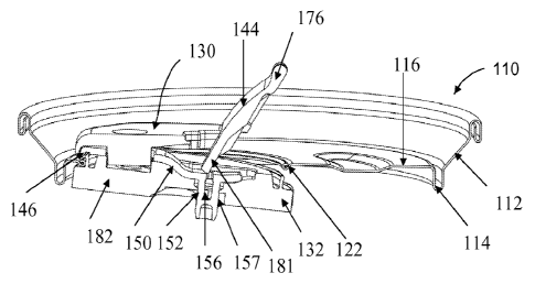
internal can pressure is controllably vented before fully opening closure 130.
However,
location portion 158' remains aligned in the aperture 191.
[00119] After venting, a user may rotate tab 176 more fully, such as
approximately to
45 degrees, and optionally apply a downward force either by directly
contacting and
pushing onto closure 130 or by transmitting a force through the tab 176. The
action of
tab 176 and the optional downward force disengages seals 136 and 138. Rotation
of tab
176 and the optional downward force may continue until base plate 132 easily
clears
18
CA 02705001 2010-05-05
WO 2009/062004 PCT/US2008/082753
center panel 116 to enable sliding of closure 130 to expose aperture 120. The
gap
between the top of ring 186 and curl 122 is approximately 0.76mm (0.0299
inch).
[00120] To reclose, a user may grasp tab 176 and pull or push closure 130
until it is
aligned with aperture 120, then put upwardly to engage seals 136 and 138.
[00121] Figs 22 through 25 illustrate another embodiment of recloseable and
resealable end 210, which includes a peripheral wall 212, a countersink 214 at
the base
of wall 212, a center panel 216, and a closure 230. End 210 includes an
aperture 220
formed in center panel 216 about a curl 222.
[00122] Closure 230 includes a base plate 232 and a top plate assembly 234,
and
forms a bore seal 236 and a face seal 238 with curl 222. Top plate assembly
234
includes a cover plate 242 and a tab plate 244.
[00123] Cover plate 242 includes a pivotable structural portion or dome plate
262 and
an anchor plate 263. Dome plate 262 and anchor plate 263 are separated by a
groove
280 that functions as a living hinge, and may have the stress whitening,
tamper evident
features described above.
[00124] Cover plate 242 includes a cylindrical pin 255 extending downwardly
from
its underside. Cover plate 242 is separated from tab plate 244 by a living
hinge 277,
which may function as a living hinge and as tamper evidence. Anchor plate 263
includes
a rivet aperture 252 and an arcuate slot 253 therethrough.
[00125] Base plate 232 includes a planar (or nearly planar) plate member 282,
a
continuous, circumferential flange 284 extending from a periphery of plate
member 282,
and a continuous ring 286 extending upwardly from flange 284. A pair of wings
298a
and 298b extend on opposite sides of flange 84, as shown in Fig. 25.
[00126] Base plate 232, flange 284, and ring 286 preferably have approximately
the
same shape as aperture 220. Base plate 232 includes a rivet 292 and a pair of
arcuate
tongues 293 that extend upwardly from plate member 282.
[00127] Center panel 216 also includes an aperture 350 that is spaced apart
from pour
aperture 220. A grommet or insert 352 is affixed into aperture 350, preferably
in a press
fit. Insert 352 has a through hole 253 defined by a sealing surface 254.
Preferably, base
plate 232 and insert 352 are injection molding in a unitary piece such that
plate 232 and
insert 352 are held together by bridges. Upon application of the unitary,
injection
19
CA 02705001 2010-05-05
WO 2009/062004 PCT/US2008/082753
molded part to center panel 216, the bridges are ruptured, which enables base
plate 232
to function as described herein.
[00128] In its assembled state, base plate 232 is located on the underside of
center
panel 216 such that the flat surface of flange 284 is in contact with the
underside of curl
222 to form face seal 238, and the outboard portion of ring 286 (preferably
recess 290)
contacts the innermost portion of curl 222 to form bore seal 236.
[00129] Rivet 292 extends through rivet aperture 350 in anchor plate 263 to
affix the
top and bottom plates together. Arcuate tongues 293 extend into arcuate slots
253. Pin
255 is located in insert aperture 250 such that pin 255 forms a seal with
aperture sealing
surface 254.
[00130] To actuate closure 230, a user may place a finger beneath tab plate
244 to
rotate dome plate 262 of cover plate 242 upwardly about hinge 280, then
translate
closure 230 relative to opening 220. Tabs 298a and 298b preferably are not
employed
for the opening process, but rather are used as guides during assembly and
application of
closure 230 to center panel 216.
[00131] From the vented position, the user continues to grip tab plate 244 and
pulls or
slides closure 230 to expose end aperture 220 to enable drinking or pouring
from the can
end. Thus, closure 230 may be actuated by gripping tab plate 244, twisting it,
and
pulling it, without the user letting go of tab plate 244.
[00132] To the extent necessary, the attachment of top plate 234 to base
plate 232 by
rivet 292 has the inherent capability of flexing to enable base plate 232 to
ride
underneath center panel 216 and to enable tab plate 244 to ride overtop center
panel 216.
[00133] To reclose closure 230, a user grasps tab plate 234 and pushes or
slides
closure 230 over aperture 220 until ring 286 aligns with center panel aperture
220. The
user then pulls generally upwardly on tab plate 244 with a force sufficient to
deflect ring
286 such that bead 288 snaps over curl 222.
[00134] The present inventions are illustrated by the description of several
embodiments. The present invention, however, is not limited to the particular
embodiments described herein. Rather the present invention encompasses any
combination of the features of any of the embodiments and natural variations
thereof, as
will be understood by persons familiar with closure technology.