Note: Descriptions are shown in the official language in which they were submitted.
CA 02705026 2012-08-03
PIVOTALLY ACTIVATED CONNECTOR COMPONENTS FOR
FORM-WORK SYSTEMS AND METHODS FOR USE OF SAME
[0001] Technical Field
[0002] This invention relates to form-work systems for fabricating structural
parts for
buildings, tanks and/or other structures out of concrete or other similar
curable
construction materials. Particular embodiments of the invention provide
connector
components for modular stay-in-place forms and methods for providing
connections
between modular form units.
Background
[0003] It is known to fabricate structural parts for buildings, tanks or the
like from
concrete using modular stay-in-place forms. Such structural parts may include
walls,
ceilings or the like. Examples of such modular stay in place forms include
those
described US patent publication No. 2005/0016103 (Piccone) and PCT publication
No.
W096/07799 (Sterling). A representative drawing depicting a partial form 28
according
to one prior art system is shown in top plan view in Figure 1. Form 28
includes a plurality
of wall panels 30 (e.g. 30A, 30B, 30D), each of which has an
CA 02705026 2010-05-06
WO 2009/059410 PCT/CA2008/001951
- 2 -
inwardly facing surface 31A and an outwardly facing surface 31B. Each of
panels
30 includes a terminal male T-connector component 34 at one of its transverse,
vertically-extending edges (vertical being the direction into and out of the
Figure 1
page) and a terminal female C-connector component 32 at its opposing vertical
edge. Male T-connector components 34 slide vertically into the receptacles of
female C-connector components 32 to join edge-adjacent panels 30 to form a
pair of
substantially parallel wall segments (generally indicated at 27, 29).
Depending on
the needs for particular wall segments 27, 29, different panels 30 may have
different
transverse dimensions. For example, comparing panels 30A and 30B, it can be
seen
that panel 30A has approximately 1/4 of the transverse length of panel 30B.
[0004] Form 28 includes support panels 36 which extend between, and connect to
each of, wall segments 27, 29 at transversely spaced apart locations. Support
panels
36 include male T-connector components 42 slidably received in the receptacles
of
female C-connector components 38 which extend inwardly from inwardly facing
surfaces 31A or from female C-connector components 32. Form 28 comprises
tensioning panels 40 which extend between panels 30 and support panels 36 at
various locations within form 28. Tensioning panels 40 include male T-
connector
components 46 received in the receptacles of female C-connector components 38.
[0005] In use, form 28 is assembled by slidable connection of the various male
T-connector components 34, 42, 46 in the receptacles of the various female
C-connectors 32, 38. Liquid concrete is then poured into form 28 between wall
segments 27, 29. The concrete flows through apertures (not shown) in support
panels 36 and tensioning panels 40 to fill the inward portion of form 28 (i.e.
between wall segments 27, 29). When the concrete solidifies, the concrete
(together
with form 28) may provide a structural component (e.g. a wall) for a building
or
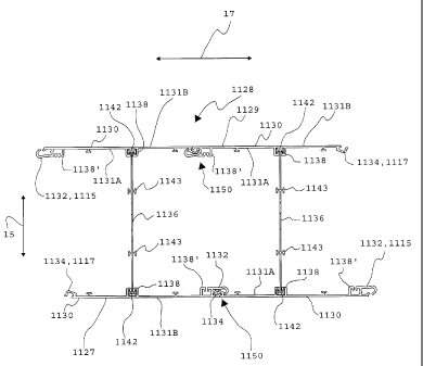
other structure.
[0006] One well-known problem with prior art systems is referred to
colloquially as
"unzipping". Unzipping refers to the separation of connector components from
one
another due to the weight and/or outward pressure generated by liquid concrete
when it is poured into form 28. By way of example, unzipping may occur at
connector components 32, 34 between panels 30. Figure 2 schematically depicts
the
unzipping of a prior art connection 50 between male T-connector component 34
and
corresponding female C-connector component 32 at the edges of a pair of
edge-adjacent panels 30. The concrete (not explicitly shown) on the inside 51
of
connection 50 exerts outward forces on panels 50 (as shown at arrows 52, 54).
These outward forces tend to cause deformation of the connector components 32,
34. In the Figure 2 example illustration, connector components 32, 34 exhibit
CA 02705026 2010-05-06
WO 2009/059410 PCT/CA2008/001951
-3 -
deformation in the region of reference numerals 56, 58, 60, 62, 64, 68. This
deformation of connector components 32, 34 may be referred to as unzipping.
[0007] Unzipping of connector components can lead to a number of problems. In
addition to the unattractive appearance of unzipped connector components,
unzipping can lead to separation of male connector components 34 from female
connector components 32. To counteract this problem, prior art systems
typically
incorporate support panels 36 and tensioning panels 40, as described above.
However, support panels 36 and tensioning panels 40 represent a relatively
large
amount of material (typically plastic) which can increase the overall cost of
form 28.
Furthermore, support panels 36 and tensioning panels do not completely
eliminate
the unzipping problem. Notwithstanding the presence of support panels 36 and
tensioning panels 40, in cases where male connector components 34 do not
separate
completely from female connector components 32, unzipping of connector
components 32, 34 may still lead to the formation of small spaces (e.g. spaces
70,
71) or the like between connector components 32, 34. Such spaces can be
difficult
to clean and can represent regions for the proliferation of bacteria or other
contaminants and can thereby prevent or discourage the use of form 28 for
particular applications, such as those associated with food storage or
handling or
other applications requiring sanitary conditions or the like. Such spaces can
also
permit the leakage of liquids and/or gasses between inside 51 and outside 53
of
panels 30. Such leakage can prevent or discourage the use of foiin 28 for
applications where it is required that form 28 be impermeable to gases or
liquids.
Such leakage can also lead to unsanitary conditions on the inside of form 28.
[0008] There is a general desire to provide modular form components and
connections therefor which overcome or at least ameliorate some of the
drawbacks
with the prior art.
Brief Description of Drawings
[0009] In drawings which depict non-limiting embodiments of the invention:
Figure 1 is a top plan view of a prior art modular stay-in-place form;
Figure 2 is a magnified partial plan view of the Figure 1 form, showing the
unzipping of a connection between wall panels;
Figure 3 is a top plan view of a modular stay-in-place form according to a
particular embodiment of the invention;
Figure 4 is a top plan view of a modular stay-in-place form according to
another particular embodiment of the invention;
CA 02705026 2010-05-06
WO 2009/059410 PCT/CA2008/001951
- 4 -
Figures 5A and 5B are plan views of modular stay-in-place forms which may
be used to fabricate a tilt-up wall according to other particular embodiments
of the
invention;
Figures 6A, 6B and 6C represent partial side plan views of the panels and
the support members of the forms of Figures 3, 4, 5A and 5B and of the
tensioning
components of the Figures 4 and 5B form;
Figures 7A-7E represent magnified partial plan views of the connector
components for implementing the edge-to-edge connections between edge-adjacent
panels of the forms of Figures 3, 4, 5A and 5B and a method of coupling the
connector components to form such edge-to-edge connections;
Figure 7F is a magnified partial plan view of the connector components for
implementing edge-to-edge connections between edge-adjacent panels of the
forms
of Figures 3, 4, 5A and 5B which shows the interleaved protrusions between the
connector components;
Figures 8A-8C represent magnified partial views of curved connector
components for implementing edge-to-edge connection between edge-adjacent
panels
according to another particular embodiment of the invention and a method of
coupling the connector components to form such edge-to-edge connections;
Figures 9A-9C represent magnified partial views of curved connector
components and a plug component for implementing edge-to-edge connection
between edge-adjacent panels according to another particular embodiment of the
invention and a method of coupling the connector components and the plug
component to form such edge-to-edge connections;
Figures 10A-10D are plan views showing modular panels used in the forms
of Figures 3 and 4 and having different transverse dimensions;
Figures 11A and 11B are plan views of an inside corner element and an
outside corner element suitable for use with the forms of Figures 3 and 4;
Figure 11C is a plan view of a complete wall form incorporating the inside
and outside corner elements of Figures 11A and 11B;
Figure 12 is a plan view of a corrugated panel according to another
embodiment of the invention;
Figure 13 is a top plan view of a modular stay-in-place form according to
another particular embodiment of the invention;
Figure 14 is a top plan view of a modular stay-in-place form according to yet
another particular embodiment of the invention;
CA 02705026 2010-05-06
WO 2009/059410
PCT/CA2008/001951
- 5 -
Figure 15 is a plan view of a modular stay-in-place one-sided form which
may be used to fabricate a tilt-up wall according to another embodiment of the
invention;
Figures 16A, 16B and 16C represent partial side plan views of the panels
and the support members of the forms of Figures 13, 14 and 15 and of the
tensioning components of the Figure 14 and Figure 15 forms;
Figures 17A-17G represent various magnified views of the connector
components for implementing the edge-to-edge connections between edge-adjacent
panels of the forms of Figures 13, 14 and 15 and a method of coupling the
connector components to form such edge-to-edge connections;
Figures 18A-18D represent plan views of various modular stay-in-place
forms according to other embodiments of the invention;
Figures 19A-19C are plan views showing modular panels of the type used in
the forms of Figures 13 and 14 and having different transverse dimensions;
Figures 20A and 20B are plan views of an outside corner element and an
inside corner element suitable for use with the forms of Figures 13 and 14;
Figure 20C is a top plan view of a wall end incorporating a pair of Figure
20A outside corner elements;
Figure 20D is a top plan view of a form incorporating the outside and inside
corner elements of Figures 20A and 20B;
Figure 21A is a top plan view of a form used to form a cylindrical column
according to a particular embodiment of the invention; and
Figure 21B is a top plan view of a form used to form a hollow annular
column according to a particular embodiment of the invention.
Description
[0010] Throughout the following description specific details are set forth in
order to
provide a more thorough understanding to persons skilled in the art. However,
well
known elements may not have been shown or described in detail to avoid
unnecessarily obscuring the disclosure. Accordingly, the description and
drawings
are to be regarded in an illustrative, rather than a restrictive, sense.
[0011] Figure 3 is a partial top plan view of a modular stay-in-place form 128
according to a particular embodiment of the invention which may be used to
fabricate a portion of a wall of a building or other structure. Form 128 of
the Figure
3 embodiment includes wall panels 130 and support members 136. The components
of form 128 (i.e. panels 130 and support members 136) are preferably
fabricated
from a lightweight and resiliently deformable material (e.g. a suitable
plastic) using
CA 02705026 2010-05-06
WO 2009/059410 PCT/CA2008/001951
- 6 -
an extrusion process. By way of non-limiting example, suitable plastics
include:
poly-vinyl chloride (PVC), acrylonitrile butadiene styrene (ABS) or the like.
In
other embodiments, the components of foim 128 may be fabricated from other
suitable materials, such as steel or other suitable alloys, for example.
Although
extrusion is the currently preferred technique for fabricating the components
of form
128, other suitable fabrication techniques, such as injection molding,
stamping,
sheet metal fabrication techniques or the like may additionally or
alternatively be
used.
[0012] Form 128 comprises a plurality of panels 130 which are elongated in the
vertical direction (i.e. the direction into and out of the page of Figure 3
and the
direction of double-headed arrow 19 of Figures 6A and 6B). Panels 130 comprise
inward facing surfaces 131A and outward facing surfaces 131B. In the Figure 3
illustration, all panels 130 are identical to one another, but this is not
necessary. In
general, panels 130 may have a number of features which differ from one
another as
explained in more particular detail below. As shown in Figures 3, 6A and 7A-
7F,
panels 130 incorporate first, generally female, curved connector components
132 at
one of their edges 115 and second, generally male, curved connector components
134 at their opposing edges 117. In the illustrated embodiment, panels 130
(including first and second connector components 132, 134) have a
substantially
uniform cross-section along their entire vertical length, although this is not
necessary.
[0013] In some embodiments, panels 130 are prefabricated to have different
vertical
dimensions. In other embodiments, the vertical dimensions of panels 130 may be
cut
to length. Preferably, panels 130 are relatively thin in the inward-outward
direction
(shown by double-headed arrow 15 of Figures 3) in comparison to the inward-
outward dimension of the resultant walls fabricated using form 128. In some
embodiments, the ratio of the inward-outward dimension of a structure formed
by
form 128 to the inward-outward dimension of a panel 130 is in a range of 10-
600.
In some embodiments, the ratio of the inward-outward dimension of a structure
formed by form 128 to the inward-outward dimension of a panel 130 is in a
range of
20-300.
[0014] As shown in Figure 3 and explained further below, connector components
132, 134 may be joined together to form connections 150 at edges 115, 117 of
panels 130. Panels 130 may thereby be connected in edge-adjacent relationship
to
form wall segments 127, 129. In the Figure 3 illustration, form 128 comprises
a
pair of wall segments 127, 129 which extend in the vertical direction and in
the
transverse direction (shown by double headed arrows 17 in Figures 3 and 6A).
This
CA 02705026 2010-05-06
WO 2009/059410 PCT/CA2008/001951
- 7 -
is not necessary. As explained in more particular detail below, forms used for
tilt-up
walls according to the invention need only comprise a single wall segment. In
addition, structures fabricated using forms according to the invention are not
limited
to walls. In such embodiments, groups of edge-adjacent panels 130 connected in
edge-to-edge relationship at connections 150 may be more generally referred to
as
form segments instead of wall segments. In the illustrated embodiment, wall
segments 127, 129 are spaced apart from one another in the inward-outward
direction by an amount that is relatively constant, such that wall segments
127, 129
are generally parallel. This is not necessary. In some embodiments, wall
segments
127, 129 need not be parallel to one another and different portions of forms
according to the invention may have different inward-outward dimensions.
[0015] Figures 7A-7E schematically illustrate represent magnified partial plan
views
of the connector components 132, 134 for implementing connections 150 between
edge-adjacent panels 130A, 130B of form 128 and a method of coupling connector
components 132, 134 to form such edge-to-edge connections 150. Generally
speaking, rather than sliding panels relative to one another to form
connections
between connector components, edge-adjacent panels 130A, 130B are pivoted
relative to one another such that second, generally male, curved connector
component 134 pivots into receptacle 154 of first, generally female, curved
connector component 132. The coupling of second connector component 134 to
first
connector component 132 may also involve resilient deformation of various
features
of connector components 132, 134 such that resilient restorative forces tend
to lock
connector components 132, 134 to one another (i.e. snap-together fitting).
[0016] The features of connector components 132, 134 are shown best in Figures
7A and 7B. Connector component 132 is a part of (i.e. integrally formed with)
panel 130A and includes a pair of curved arms 156A, 156B which join one
another
in region 157 to form a curved receptacle or channel 154 therebetween. Region
157
may be referred to as bight 157. Proximate arm 156A extends generally away
from
panel 130A toward bight 157 and distal arm 156B extends generally from bight
157
back toward panel 130A to form receptacle 154. Receptacle 154 comprises an
open
end 161 at an end opposite that of bight 157. In currently preferred
embodiments,
the curvatures of arms 156A, 156B are not concentric and distal arm 156B
extends
slightly toward proximate arm 156A as arms 156A, 156B extend away from bight
157. That is, the dimension of receptacle 154 (i.e separation of arms 156A,
156B) is
wider in a central portion 159 of receptacle 154 than at opening 161 of
receptacle
154.
CA 02705026 2010-05-06
WO 2009/059410 PCT/CA2008/001951
- 8 -
[0017] In the illustrated embodiment, proximate arm 156A comprises a
protrusion
158 in a vicinity of inward surface 131A of panel 130A. Protrusion 158 extends
away from inward surface 131A of panel 130A. In the illustrated embodiment,
protrusion 158 comprises a hook portion 162. The open angle between the
surface
of proximate arm 156A and hook portion 162 may be less than 900. Connector
component 132 also comprises a beveled surface 160 which joins outward facing
surface 131B of panel 130A. The open angle y between beveled surface 160 and
outward facing surface 131B of panel 130A may be greater than 270 .
[0018] Connector component 134 is part of panel 130B and comprises a curved
protrusion or prong 164 which initially extends away from inward facing
surface
131A of panel 130B. The radius of curvature of prong 164 may vary along the
length of prong 164. Depending on the curvature of prong 164, a distal portion
of
prong 164 may curve back toward inward facing surface 131A of panel 130.
Connector component 134 also comprises a plurality of projections 166, 168,
170,
172 which extend from prong 164 at spaced apart locations therealong. In the
illustrated embodiment, each of projections 166, 168, 170, 172 comprises a
distal
lobe 166A, 168A, 170A, 172A and a proximate lobe 166B, 168B, 170B, 172B.
Distal lobe 166A may comprise a forward surface 166A' (closer to the end 165
of
prong 164) for which the open angle (not explicitly enumerated) between
forward
surface 166A' and the surface of the central shaft of prong 164 is greater
than 900
.
Distal lobe 166A may comprise a rearward surface 166A" (further from the end
165
of prong 164) for which the open angle (not explicitly enumerated) between
rearward surface 166B" and the surface of the central shaft of prong 164 is
less than
90 .
[0019] Proximate lobe 166B may comprise similar forward and rearward surfaces
166B', 166B" which exhibit similar angular properties as forward and rearward
surface 166A', 166A" with respect to the surface of prong 164. Furthermore,
although not explicitly enumerated for the sake of clarity, distal lobes 168A,
170A,
172A and proximate lobes 168B, 170B, 172B may comprise forward and rearward
surfaces (similar to forward and rearward surfaces 166A', 166A") which exhibit
similar angular properties with respect to the surface of prong 164. The
relative size
of projections 166, 168, 170, 172 (i.e. the distance between the extremities
of
proximate lobes 166B, 168B, 170B, 172B and distal lobes 166A, 168A, 170A,
172A) may increase as projections 166, 168, 170, 172 are spaced further from
the
end 165 of prong 164. That is, projection 172 (lobes 172A, 172B) may be larger
than projection 170 (lobes 170A, 170B), projection 170 (lobes 170A, 170B) may
be
CA 02705026 2010-05-06
WO 2009/059410
PCT/CA2008/001951
- 9 -
larger than projection 168 (lobes 168A, 168B) and projection 168 (lobes 168A,
168B) may be larger than projection 166 (lobes 166A, 166B).
[0020] In the illustrated embodiment, connector component 134 also comprises a
receptacle 174 in a vicinity of inward surface 131A of panel 130B. Receptacle
174
opens away from inward surface 131A of panel 130B. Connector component 134
also comprises a thumb 175 that extends transversely beyond the region at
which
prong 164 extends from inward facing surface 131A of panel 130B. Thumb 175
terminates in a beveled surface 176 which joins outward facing surface 131B of
panel 130B. The open angle a between beveled surface 176 and outward facing
surface 131B of panel 130B may be less than 2700. As explained in more detail
below, the angles a, y of beveled surfaces 176, 160 may be selected such that
beveled surface 176 of connector component 134 abuts against beveled surface
160
of connector component 132 when connector components 132, 134 are coupled to
one another to form connection 150 (e.g. when outward facing surfaces 131B of
panels 130A, 130B are parallel to one another to form a portion of wall
segments
127, 129).
[0021] The coupling of connector components 132, 134 to one another to form
connection 150 between wall segments 130A, 130B is now described with
reference
to Figure 7A-7E. A user starts by placing wall segments 130A, 130B into the
configuration shown in Figure 7A. In the Figure 7A configuration, the end 165
of
prong 164 is clear of receptacle 154 between arms 156A, 156B. In the
illustrated
embodiment, the angle 0 between the inward facing surfaces 131A of panel 130A
and panel 130B may be less than about 45 when panels 130A, 130B are in the
Figure 7A configuration.
[0022] As shown in Figure 7B, a user then starts effecting a relative pivotal
(or
quasi-pivotal) motion between panel 130A and panel 130B as shown by arrow 177.
The end 165 of prong 164 approaches the end 156B' of arm 156B and opening 161
of receptacle 154. Contact between the end 165 of prong 164 and the end 156B'
of
arm 156B may cause deformation of prong 164 (e.g. in the direction of arrow
178)
and/or the deformation of arm 156B (e.g. in the direction of arrow 179).
Contact
between the end 165 of prong 164 and the end 156B' of arm 156B is not
necessary.
In some embodiments, the relative pivotal movement between panel 130A and
panel
130B may cause the end 165 of prong 164 to project at least partially into
opening
161 of receptacle 154 without contacting arms 156A, 156B. In the Figure 7B
configuration, the angle 0 between the inward facing surfaces 131A of panel
130A
and panel 130B may be in a range of 30 -75 .
CA 02705026 2010-05-06
WO 2009/059410 PCT/CA2008/001951
- 10 -
[0023] As shown in Figure 7C, the user continues to effect relative pivotal
(or
quasi-pivotal) motion between panel 130A and panel 130B as shown by arrow 177.
As a consequence of this relative pivotal motion, end 165 of prong 164 begins
to
project past the end 156B' of arm 156B and through opening 161 of curved
receptacle or channel 154. As projection 166 enters curved receptacle 154,
distal
lobe 166A may contact proximate atm 156A while proximate lobe 166B may
contact distal arm 156B. This contact may cause deformation of proximate arm
156A, distal arm 156B and/or prong 164 as curved prong 164 moves into curved
receptacle 154. The angle (greater than 90 ) of forward surface 166B' of
proximate
lobe 166B may facilitate this deformation as forward surface 166B' contacts
the end
156B' or arm 156B. In addition, as curved prong 164 enters curved receptacle
154,
there may be contact between distal lobes 166A, 168A and protrusion 158. Such
contact may cause deformation of proximate arm 156A, distal arm 156B and/or
prong 164. The angle (greater than 90 ) of forward surfaces 166A', 168A' of
distal
lobes 166A, 168A may facilitate this deformation as forward surfaces 166A',
168A'
contact protrusion 158. In the Figure 7C configuration, the angle 0 between
the
inward facing surfaces 131A of panel 130A and panel 130B may be in a range of
75 -105 .
[0024] In the illustrated view of Figure 7D, the user continues to effect
relative
pivotal (or quasi-pivotal) motion between panel 130A and panel 130B as shown
by
arrow 177. The Figure 7D configuration is similar in many respects to the
Figure
7C configuration, except that curved prong 164 projects further into curved
receptacle 154. As prong 164 continues to project into receptacle 154, there
may be
contact between distal lobe 170A and protrusion 158. Such contact may cause
the
deformation of proximate arm 156A, distal arm 156B and/or prong 164. The angle
(greater than 90 ) of forward surface 170A' of distal lobe 170A may facilitate
this
deformation as forward surface 170A' contacts protrusion 158. In addition,
once
protrusion 158 has cleared distal lobe 170A, rearward surface 170A" may
interact
with hook 162 of protrusion 158 to make it more difficult to decouple
connector
components 132, 134. More particularly, the angle (less than 90 ) between
rearward surface 170A" and the surface of the shaft of prong 164 and the angle
(Figure 7A, less than 90 ) of hook 162 tend to prevent pivotal motion of panel
130A with respect to panel 130B in a direction opposite that of arrow 177.
While
the interaction between rearward surface 170A" and hook 162 is explained
above, it
will be appreciated that the rearward surfaces 166A", 168A", 172A" could also
interact with hook 162 in a similar manner to help prevent pivotal motion of
panel
130A with respect to panel 130B in a direction opposite that of arrow 177. In
the
CA 02705026 2010-05-06
WO 2009/059410 PCT/CA2008/001951
- 11 -
Figure 7D configuration, the angle O between the inward facing surfaces 131A
of
panel 130A and panel 130B may be in a range of 1050-1500
.
[0025] The user continues to effect relative pivotal (or quasi-pivotal) motion
between panel 130A and panel 130B as shown by arrow 177 until panels 130A and
130B reach the configuration of Figure 7E. In the configuration of Figure 7E,
the
inward facing surfaces 131A and outward facing surfaces 131B of panels 130A,
130B are generally parallel (i.e. the angle between inward facing surfaces
131A of
panels 130A, 130B is at or near 1800. As prong 164 continues to project into
receptacle 154, there may be contact between distal lobe 172A and protrusion
158.
Such contact may cause the deformation of proximate arm 156A and/or prong 164.
The angle (greater than 90 ) of forward surface 172A' of distal lobe 172A may
facilitate this deformation as forward surface 172A' contacts protrusion 158.
In
addition, once protrusion 158 has cleared distal lobe 172A, protrusion 158 may
snap
(e.g by restorative deformation force) into receptacle 174. In the illustrated
embodiment, a portion of receptacle 174 comprises rearward surface 172A" of
distal
lobe 172A. Once received in receptacle 174, rearward surface 172A" of distal
lobe
172A interacts with hook 162 of protrusion 158 to lock connector components
132,
134 to one another. More particularly, the angle (less than 90 ) between
rearward
surface 172A" and the surface of prong 164 and the angle lir (less than 90 )
of hook
162 tend to prevent pivotal motion of panel 130A with respect to panel 130B in
a
direction opposite that of arrow 177. In addition, receptacle 174 comprises a
depression into the distal surface of prong 164. The "snapping" (e.g by
restorative
deformation force) of protrusion 158 into the depression of receptacle 174
tends to
help prevent pivotal motion of panel 130A with respect to panel 130B in a
direction
opposite that of arrow 177.
[0026] In the Figure 7E configuration, there is preferably contact between a
plurality of distal lobes (e.g. distal lobes 166A, 168A) and proximate arm
156A
within receptacle 154 and there is preferably contact between a plurality of
proximate lobes (e.g. proximate lobes 166B, 168B) and distal arm 156B. For
clarity, this contact is not explicitly shown in the Figure 7E illustration.
Such
contact may cause deformation of arm 156A, arm 156B and/or prong 164. In this
manner, restorative deformation forces tend to force proximate arm 156A
against
distal lobes 166A, 168A and distal arm 156B against proximate lobes 166B,
168B.
In some embodiments, projections 166, 168 and arms 156A, 156B are dimensioned
such that contact between projection 166 and arms 156A, 156B and contact
between
projection 168 and alms 156A, 156B occur at approximately the same relative
orientation of panels 130A, 130B. In particular embodiments, the restorative
CA 02705026 2010-05-06
WO 2009/059410 PCT/CA2008/001951
- 12 -
deformation forces at the points of contact between projection 166 and arms
156A,
156B and the restorative deformation forces at the points of contact between
projection 168 and arms 156A, 156B are approximately equal or within 20% of
one
another.
[0027] In the illustrated embodiment, there is also contact between end 165 of
prong
164 and the end 154A of curved receptacle 154 (i.e. in bight 157 between arms
156A, 156B). The contact between projections 166, 168 and arms 156A, 156B,
between the end 165 of prong 164 and the end 154A of curved receptacle 154 and
between protrusion 158 and receptacle 174 may provide a seal that is
impermeable
to liquids (e.g. water) or gasses (e.g. air). In some embodiments, the
surfaces of
arms 156A, 156B, projections 166, 168, 170, 172, protrusion 158 and/or
receptacle
174 may be coated with suitable material(s) which may increase this
impermeability.
Non-limiting examples of such material(s) include silicone, urethane,
neoprene,
polyurethane, food grade plastics and the like. In addition to being coated
with
suitable coating materials, the contact surfaces between arms 156A, 156B and
projections 166, 168 may be provided with friction enhancing surface textures
(e.g.
ridges having saw-tooth shapes or other shapes), which may help to prevent
pivotal
motion of panel 130A with respect to panel 130B in a direction opposite that
of
arrow 177.
[0028] In the configuration of Figure 7E, beveled surface 176 of male
connector
component 134 abuts against beveled surface 160 of female connector component
132. As discussed above, the respective angles (I), a of beveled surface 160,
176
with respect to outward facing surfaces 131B of their corresponding panels
130A,
130B are selected such that beveled surfaces 160, 176 abut against one another
when
connector components 132, 134 are in the Figure 7E configuration (i.e. when
panels
130A, 130B are generally parallel to one another). Beveled surfaces 160, 176
may
also be coated with suitable coating materials or provided with friction
enhancing
surface textures to improve the impermeability or increase the friction of the
abutment joint therebetween. It will be appreciated that connecting panels
130A,
130B to form connection 150 need not proceed through all of the steps shown in
Figures 7A-7E. Panels 130A, 130B may start in a configuration similar to that
of
Figure 7C and then proceed through the configurations of 7D and 7E, for
example.
[0029] Figure 7F is another schematic view of connection 150 between connector
components 132, 134 of panels 130A, 130B which shows a transverse midplane 180
of connection 150. It can be seen from Figure 7F that connector component 132
comprises a plurality of projecting elements 182A, 182B, 182C which project
transversely from one side of midplane 180 (i.e. the side of panel 130A) to
the
CA 02705026 2010-05-06
WO 2009/059410 PCT/CA2008/001951
- 13 -
opposing side of midplane 180. Similarly, connector component 134 comprises a
plurality of projecting elements 184A, 184B which project transversely from
one
side of midplane 180 (i.e. the side of panel 130B) to the opposing side of
midplane
180. These projecting elements 182A, 182B, 182C, 184A, 184B interleave with
one
another to provide multiple points of contact (abutments) which tend to
prevent
connection 150 from unzipping. More particularly, as shown in Figures 7E and
7F,
projecting element 182A corresponds to the abutment between beveled surfaces
176,
160, projecting element 184A corresponds to the abutment of protrusion 158 and
thumb 175, projecting element 182B corresponds to the abutment of hook 162 of
protrusion 158 and rearward surface 172A" of projection 172A and projecting
elements 184B, 182C correspond to the interaction between projections 166,
168,
170 on prong 164 and arms 156A, 156B.
[0030] Interleaved projecting elements 182A, 182B, 182C, 184A, 184B tend to
prevent connection 150 from unzipping. More particularly, if a
disproportionately
large amount of outward force 186 is applied to panel 130A (relative to panel
130B), then the contact between protrusion 158 and thumb 175 and the contact
between proximate arm 156A and prong 164 both tend to prevent unzipping of
connection 150. Similarly, if a disproportionately large amount of outward
force
188 is applied to panel 130B (relative to panel 130A), then the contact
between
beveled surfaces 160, 176, the contact between rearward surface 172A" of
distal
lobe 172A and hook 162 of protrusion 158 and the contact between prong 164 and
distal arm 156B all tend to prevent unzipping of connection 150.
[0031] In addition, when connection 150 formed by interleaved projecting
elements
182A, 182B, 182C, 184A, 184B is encased in concrete and the concrete is
allowed
to solidify, the solid concrete may exert forces that tend to compress
interleaved
projecting elements 182A, 182B, 182C, 184A, 184B toward one another.
[0032] In the Figure 3 embodiment, form 128 comprises support members 136
which extend between wall segments 127, 129. Support members 136 are also
shown in Figure 6B. Support members 136 comprise connector components 142 at
their edges for connecting to corresponding connector components 138 on inward
surfaces 131A of panels 130. Support members 136 may brace opposing panels 130
and connect wall segments 127, 129 to one another.
[0033] In the illustrated embodiment, connector components 138 on inward
surfaces
131A of panels 130 are male T-shaped connector components 138 which slide into
the receptacles of female C-shaped connector components 142 at the edges of
support members 136. This is not necessary. In general, where form 128
includes
support members 136, connector components 138,142 may comprise any suitable
CA 02705026 2010-05-06
WO 2009/059410 PCT/CA2008/001951
- 14 -
complementary pair of connector components and may be coupled to one another
by
sliding, by deformation of one or both connector components or by any other
suitable coupling technique. By way of non-limiting example, connector
components
138 on panels 130 may comprise female C-shaped connectors and connector
components 142 on support members 136 may comprise male T-shaped connectors
which may be slidably coupled to one another.
[0034] In the illustrated embodiment of Figure 3, each panel 130 comprises
three
connector components 138 between its edges 115, 117 (i.e. between connector
components 132, 134), which facilitate the connection of up to three support
members 136 to each panel 130. This is not necessary. In general, panels 130
may
be provided with any suitable number of connector components 138 to enable the
connection of a corresponding number of support members 136, as may be
necessary for the particular strength requirements of a given application. In
addition, the mere presence of connector components 138 on panels 130 does not
necessitate that support members 136 are connected to each such connector
component 138. In general, the spacing of support members 136 may be
determined
as necessary for the particular strength requirements of a given application
and to
minimize undesirably excessive use of material.
[0035] Support members 136 are preferably apertured (see apertures 119 of
Figure
6B) to allow liquid concrete to flow in the transverse directions between wall
segments 127, 129. Although not explicitly shown in the illustrated views,
reinforcement bars (commonly referred to as rebar) may also be inserted into
form
128 prior to pouring the liquid concrete. Where required or otherwise desired,
transversely extending rebar can be inserted so as to extend through apertures
119 in
support members 136. If desired, vertically extending rebar can then be
coupled to
the transversely extending rebar.
[0036I Figure 4 is a partial top plan view of a modular stay-in-place form 228
according to another particular embodiment of the invention which may be used
to
form a wall of a building or other structure. Form 228 of Figure 4
incorporates
panels 130 and support members 136 which are substantially identical to panels
130
and support members 136 of form 128 and similar reference numbers are used to
refer to the similar features of panels 130 and support members 136. Panels
130 are
connected as described above (at connections 150) in edge-adjacent
relationship to
provide wall segments 227, 229. Form 228 differs from form 128 in relation to
the
spacing in the transverse direction (arrow 17) between adjacent support
members
136. Form 228 also incorporates tensioning members 140A, 140B (collectively,
CA 02705026 2010-05-06
WO 2009/059410 PCT/CA2008/001951
- 15 -
tensioning members 140) which are not present in form 128. Tensioning members
140 are also illustrated in Figure 6C.
[0037] In the Figure 4 embodiment, connector components 138 on inward surfaces
131A of panels 130 are referred to individually using reference numerals 138A,
138B, 138C. Connector component 138A is most proximate to first, generally
female connector component 132 on edge 115 (Figure 6A) of panel 130, connector
component 138C is most proximate to second, generally male connector component
134 on edge 117 (Figure 6A) of panel 130 and connector component 138B is
located
between connector components 138A, 138C. In the illustrated embodiment of
Figure 4, support members 136 extend between every third connector component
138 to provide one support member 136 per panel 130. More particularly, in the
Figure 4 embodiment, support members 136 extend between connector components
138C of opposing panels 130 on wall segments 227 and 229. The connection
between connector components 142 of support members 136 (which, in the
illustrated embodiment are female C-shaped connector components) and connector
components 138C of panels 130 (which in the illustrated embodiment are male T-
shaped connector components) may be substantially similar to the connections
discussed above for form 128. However, this is not necessary. In general,
connector
components 138 and 142 may be any complementary pairs of connector components
and may be coupled to one another by sliding, by deformation of one or both
connector components or by any other suitable coupling technique.
[0038] Form 228 incorporates tensioning members 140 which extend angularly
between support members 136 and panels 130. In the illustrated embodiment,
tensioning members 140 comprise connector components 141A, 141B at their
opposing edges. Connector components 141A are complementary to connector
components 138A, 138B on inward surfaces 131A of panels 130 and connector
components 141B are complementary to connector components 143 on support
members 136. In the illustrated embodiment, connector components 138A, 138B of
panels 130 and connector components 143 of support members 136 are male T-
shaped connector components which slide into the receptacles of female C-
shaped
connector components 141A, 141B of tensioning members 140. However, this is
not necessary. In general, connector components 138 and 141A and connector
components 143 and 141B may be any complementary pairs of connector
components and may be coupled to one another by sliding, by deformation of one
or
both connector components or by any other suitable coupling technique.
CA 02705026 2010-05-06
WO 2009/059410 PCT/CA2008/001951
- 16 -
[0039] Tensioning members 140 preferably comprise apertures 171 which allow
concrete flow and for the transverse extension of rebar therethrough (see
Figure
6C).
[0040] As mentioned above, in the illustrated embodiment, support members 136
extend between connector components 138C of opposing panels 130 of wall
segment
229 and wall segment 227. With this configuration of support members 136
relative
to panels 130, one tensioning member 140A out of every pair of tensioning
members 140 can be made to reinforce connections 150 between panels 130. More
particularly, tensioning members 140A may extend at an angle from support
member 136 (i.e. at the connection between connector components 141B, 143) on
one transverse side of connection 150 to panel 130 (i.e. at the connection
between
connector components 141A, 138A) on the opposing transverse side of connection
150. The other tensioning member 140B of each pair of tensioning members 140
may extend at an angle between support member 136 (i.e. at the connection
between
connector components 141B, 143) to panel 130 (i.e. at the connection between
connector components 141A, 138B).
[0041] Tensioning members 140A, which span from one transverse side of
connections 150 to the opposing transverse side of connections 150, add to the
strength of connections 150 and help to prevent unzipping of connections 150.
However, it is not necessary that tensioning members 140A span connections 150
in
this manner. In other embodiments, support members 136 may extend between wall
segments 227, 229 at different connector components. By way of non-limiting
example, support members 136 may extend between wall segments 227, 229 at the
midpoint of each panel 130, such that connector components 142 of support
members 136 are coupled to connector components 138B of panels 130. With this
configuration of support members 136 relative to panels 130, tensioning
members
140 may extend at angles between support members 136 (i.e. a connection
between
connector components 141A, 143 and a connection between connector components
141B, 143) and panels 130 (i.e. a connection between connector components
141A,
138A and a connection between connector components 141A, 138C).
[0042] In some embodiments, tensioning members 140 are not necessary.
Tensioning members 140 need not generally be used in pairs. By way of non-
limiting example, some forms may use only tensioning members 140A which may
or may not be configured to span connections 150. In some embodiments, support
members 136 and/or tensioning members 140 may be employed at different
spacings
within a particular form. Form 228 incorporates components (i.e. panels 130
and
support members 136) which are substantially similar to the components of form
CA 02705026 2010-05-06
WO 2009/059410 PCT/CA2008/001951
- 17 -
128 described herein. In various different embodiments, form 228 may be
modified
as discussed herein for any of the modifications described for form 128.
[0043] In operation, forms 128, 228 may be used to fabricate a wall by
pivotally
connecting panels 130 to make connections 150 between edge-adjacent panels 130
and by slidably connecting connector components 142 of support members 136 to
connector components 138 of panels 130 to connect wall segments 127, 129 to
one
another. If it is desired to include tensioning members 140, tensioning
members 140
may then be attached between connector components 143 of support members 136
and connector components 138 of panels 130. Panels 130 and support members 136
may be connected to one another in any orientation and may then be placed in a
vertical orientation after such connection. Walls and other structures
fabricated from
panels 130 generally extend in two dimensions (referred to herein as the
vertical
dimension (see arrow 19 of Figures 6A and 6B) and the transverse dimension
(see
arrow 17 of Figure 3)). However, it will be appreciated that walls and other
structures fabricated using forms 128, 228 can be made to extend in any
orientation
and, as such, the terms "vertical" and "transverse" as used herein should be
understood to include other directions which are not strictly limited to the
conventional meanings of vertical and transverse. In some embodiments, panels
130
may be deformed or may be prefabricated such that their transverse extension
has
some curvature.
[0044] If necessary or otherwise desired, transversely extending rebar and/or
vertically extending rebar can then be inserted into form 128, 228. After the
insertion of rebar, liquid concrete may be poured into form 128, 228. When the
liquid concrete solidifies, the result is a wall or other structure that has
two of its
surfaces covered by stay-in-place form 128, 228.
[0045] Panels 130 of forms 128, 228 may be provided in modular units with
different transverse dimensions as shown in Figures 10A, 10B, 10C and 10D.
Panel
130D of Figure 10D has a transverse dimension X between connector components
132, 134 and has no connector components 138 for connection to support members
136 or tensioning members 140. Panel 130D may be referred to as a single-unit
panel. Panel 130C of Figure 10C is a double-unit panel, with a transverse
dimension
2X between connection components 132, 134 and a single connector component 138
for possible connection to a support member 136 or a tensioning members 140.
Similarly, panels 130B, 130A of Figures 10B, 10A are triple and quadruple-unit
panels, with transverse dimensions 3X, 4X between connector components 132,
134
and two and three connector components 138 respectively for possible
connection to
support members 136 or tensioning members 140.
CA 02705026 2010-05-06
WO 2009/059410 PCT/CA2008/001951
- 18 -
[0046] Figures 11A and 11B are plan views of an inside 900 corner element 190
and
an outside 90 corner element 192 suitable for use with the forms of Figures 3
and 4
and Figure 11C is a plan view of a complete wall form 194 incorporating the
inside
and outside corner elements 190, 192 of Figures 11A and 11B. In the
illustrated
embodiment, inside corner element 190 comprises a generally female curved
connector component 132 at one of its edges and a generally male curved
connector
component 134 at is opposing edge. Similarly, the illustrated embodiment of
outside
corner element 192 comprises a generally female curved connector component 132
at one of its edges and a generally female curved connector component 134 at
is
[004'7] Figure 11C schematically illustrates a complete wall form 194
fabricated
using a series of panels 130, inside and outside corner components 190, 192
and
support members 136. In the particular example form 194 of Figure 11C, panels
130 include single-unit panels 130D and triple-unit panels 130B. It will be
[0048] Figures 5A and 5B respectively represent modular stay-in-place forms
328,
428 which may be used to fabricate tilt-up walls according to other particular
embodiments of the invention. The modular components of form 328 (Figure 5A)
and their operability are similar in many respects to the modular components
of
CA 02705026 2010-05-06
WO 2009/059410 PCT/CA2008/001951
- 19 -
[0049] The modular components of form 428 (Figure 5B) and their operability
are
similar in many respects to the modular components of form 228 (Figure 4). In
particular, form 428 (Figure 5B) incorporates panels 130, support members 136
and
tensioning members 140 which are similar to panels 130, support members 136
and
tensioning members 140 of form 228 and are connected to one another as
described
above to form a single wall segment 427 that is substantially similar to wall
segment
227 of form 228. Form 428 differs from form 228 in that form 428 does not
include
panels 130 to form a wall segment that opposes wall segment 427 (i.e. form 428
comprises a single-sided form and does not include an opposing wall segment
like
wall segment 229 of form 228). In addition, form 428 differs from form 228 in
that
form 428 only includes tensioning members 140 that connect to wall segment 427
(i.e. form 428 does not include tensioning members 140 that attach to an
opposing
wall segment like wall segment 229 of form 228).
[0050] In operation, forms 328, 428 are assembled by coupling connector
components 132, 134 of panels 130 together as described above to fabricate a
single
wall segment 327, 427. In form 328, support members 136 are then coupled to
panels 130 as described above for form 128, except that the coupling between
connector components 142 and connector components 138 is made at one side
only.
In form 428, support members 136 and tensioning members 140 are then coupled
to
panels 130 as described above for form 228, except that the coupling between
connector components 142 and connector components 138C is made at one side
only
and tensioning members 140 are coupled to support members 136 (at connector
components 141B, 143) and to panels 130 (at connector components 141A, 138B,
138A) at one side only.
[0051] Forms 328, 428 may be assembled on, or otherwise moved onto, a
generally
horizontal table or the like, such that outward facing surfaces 131B of panels
130
are facing downward and the vertical and transverse extension of panels 130 is
in
the generally horizontal plane of the table. The table may be a vibrating
table. In
some embodiments a table is not required and a suitable, generally horizontal
surface may be used in place of a table. If required, rebar may be inserted
into form
328, 428 while the form is horizontally oriented. Transversely extending rebar
may
project through apertures 119 of support members 136 and apertures 171 of
tensioning members 140. Edges (not shown) of form 328, 428 may be fabricated
on
the table in any suitable manner, such as using conventional wood form-work.
Concrete is then poured into form 328, 428 and allowed to flow through
apertures
119 of support members 136 and through apertures 171 of tensioning members
140.
CA 02705026 2010-05-06
WO 2009/059410 PCT/CA2008/001951
- 20 -
The liquid concrete spreads to level itself (perhaps with the assistance of a
vibrating
table) in form 328, 428.
[0052] The concrete is then allowed to solidify. Once solidified, the
resultant wall is
tilted into a vertical orientation. The result is a concrete wall segment (or
other
structure) that is coated on one side with the panels 130 of form 328, 428.
Panels
130 are anchored into the concrete wall by support members 136 and tensioning
members 140. Structures (e.g. building walls and the like) may be formed by
tilting
up a plurality of wall segments in place. Advantageously, the outward facing
surfaces 131B of panels 130 provide one surface of the resultant wall made
using
forms 328, 428. Outward facing surfaces 131B of panels 130 may provide a
finished
wall surface 333, 433. In some applications, such as in warehouses and box
stores
for example, it may be desirable to have finished wall surface 333, 433 on the
exterior of a building, whereas the finish of the interior wall surface is
relatively
less important. In such applications, wall segments fabricated using form 328,
428
can be tilted up such that panels 130 have outward facing surfaces 131B
oriented
toward the exterior of the building. In other applications, such as where
hygiene of
the interior of a building is important (e.g. food storage), it may be
desirable to
have finished wall surface 333,433 on the interior of a building, whereas the
finish
of the exterior wall surface is relatively less important. In such
applications, wall
segments fabricated using form 328, 428 can be tilted up such that panels 130
have
outward facing surfaces 131B oriented toward the interior of the building.
[0053] The use of forms 328, 428 to fabricate tilt-up walls may involve the
same or
similar procedures (suitably modified as necessary) as those described for the
fabrication of tilt-up walls or lined concrete structures using modular stay-
in-place
forms in the co-owned PCT application No. PCT/CA2008/000608 filed 2 April
2008 and entitled "METHODS AND APPARATUS FOR PROVIDING LININGS
ON CONCRETE STRUCTURES" (the "Structure-Lining PCT Application"),
which is hereby incorporated herein by reference. Form 328 may be anchored to
the
concrete by support members 136, by connector components 138 and by connector
components 132, 134 of connections 150. Similarly, form 428 may be anchored to
the concrete by support members 136, by connector components 138, by connector
components 132, 134 of connections 150 and by tensioning members 140. Other
anchoring components similar to any of the anchoring components disclosed in
the
Structure-Lining PCT Application may additionally or alternatively be used.
[0054] Figures 8A-8C schematically illustrate another embodiment of curved
connector components 532, 534 and the coupling of first, generally male
connector
component 534 to second, generally female connector component 532 to make a
CA 02705026 2010-05-06
WO 2009/059410 PCT/CA2008/001951
- 21 -
connection 550 between panels 530A, 530B. For clarity, only portions of panels
530A, 530B are shown in Figures 8A-8C, it being understood that panels 530A,
530B may be substantially similar to panels 130 described above, except for
connector components 532, 534. Curved connector components 532, 534 and their
use to make connection 150 are similar in many respects to connector
components
132, 134 described above. For brevity only the differences between connector
components 532, 534 and connector components 132, 134 are detailed herein. In
other respects, connector components 532, 534 should be understood to be
similar
to, operate in a manner similar to and incorporate variations which are
similar to
those of connector components 132, 134.
[0055] Male connector component 534 comprises a prong 564. Unlike prong 164 of
male connector component 134, prong 564 of male connector component 534
extends generally away from panel 530A in the transverse direction, whereas
prong
164 of male connector component 134 generally curves back toward a central
portion (not specifically enumerated) of panel 130. Male connector component
534
also comprises a plurality of protrusions 566, 568, 570 having proximate lobes
566A, 568A, 570A and distal lobes 566B, 568B, 570B. As shown in Figure 8A,
lobes 566A, 566B include forward surfaces 566A', 566B' and rearward surfaces
566A", 566B". The angular features of forward surfaces 566A', 566B' and
rearward surfaces 566B', 566B" relative to the surface of the shaft of prong
564
may be similar to those of forward surfaces 166A', 166B' and rearward surfaces
166B', 166B" described above. Furthermore, although not explicitly enumerated
for
the sake of clarity, distal lobes 568A, 570A and proximate lobes 568B, 570B
may
comprise similar forward and rearward surfaces which exhibit similar angular
properties with respect to the surface of prong 564. In some embodiments, the
size
of lobes 566, 568, 570 may increase along the extension of prong 564. That is,
lobes 566 may be larger than lobes 568 which may be larger than lobes 570.
[0056] Male connector component 534 also comprises a thumb 575 similar to
thumb
175 of connector component 134. Thumbs 575 comprises a beveled surface 576
which forms an angle a with outward facing surface 131B of connector component
530A. The open angle a may be less than 2700. Thumb 575 also comprises a hook
562 (Figure 8B). Hook 562 may be on a surface opposite beveled surface 576.
Hook
562 may have an open angle * less than 90 .
[0057] Female connector component 532 comprises distal curved arm 556A and
proximate curved arm 556B, both of which extend away from inward facing
surface
531A of panel 530B to define curved receptacle 554. Unlike receptacle 154 of
female connector component 132, receptacle 554 of female connector component
CA 02705026 2010-05-06
WO 2009/059410 PCT/CA2008/001951
- 22 -
532 has a bight 557 (Figure 8B), which is relatively proximate to inward
facing
surface 531A of panel 530, and an opening 561, which is relatively distal to
inward
facing surface 531A of panel 530. In contrast, receptacle 154 of female
connector
component 132 has a bight 157 which is relatively distal from inward facing
surface
131A of panel 130A and an opening 161 which is relatively proximate to inward
facing surface 131A of panel 130A. In some embodiments, channel 564 is
narrower
in the region of opening 561 and increases in width as it gets closer to bight
557.
[0058] Female connector component 532 also comprises a receptacle 574 (Figure
8B) which is similar to receptacle 174 of female connector component 534.
Receptacle 574 comprises a thumb 579 which is shaped similarly to thumb 575 of
connector component 534 and also comprises a hook 574' which is complementary
to hook 562 of male connector component 534. The interior angle y of hook 574'
may be less than 90 . One portion of the surface of receptacle 574 or some
other
surface of female connector component 532 may comprise a beveled surface 560
(Figure 8A) which is beveled in relation to outward facing surface 531B of
panel
530B. In some embodiments, the open angle between beveled surface 560 and
outward facing surface 531B of panel 530B is greater than 270 . In addition,
the
open angle of beveled surface 560 is preferably complementary with the open
angle a of beveled surface 576, such that beveled surfaces 560, 576 abut
against one
another when connector components 532, 534 are in the connected configuration
of
Figure 8C (i.e. when outward facing surfaces 531B of panels 530A, 530B are
parallel to one another).
[0059] In operation, a user couples connector components 532, 534 to one
another
(and thereby couples panels 5:30A, 530B to one another) by sliding panels
530A,
530B relative to one another, such that connector components 532, 534 are
partially
engaged to one another and then pivoting panels 530A, 530B relative to one
another, such that restorative deformation forces lock connector components
532,
534 to one another to complete the connection. The connection of connector
components 532, 534 starts with the configuration of Figure 8A, where a user
starts
with outward facing surfaces 531B of panels 530A, 530B at an angle O in an
angular
range of 110 -160 relative to one another and then slides panels 530A, 530B
relative to one another, such that curved prong 564 projects into curved
receptacle
554 as shown in Figure 8A. The configuration of Figure 8A may be referred to
as a
"loose fit" configuration.
[0060] The user then begins to pivot panel 530B relative to 530A in the
direction of
arrow 577 as shown in Figure 8B. In the configuration of Figure 8B, the angle
between outward facing surfaces 531B of panels 530A, 530B may be in an angular
CA 02705026 2010-05-06
WO 2009/059410 PCT/CA2008/001951
- 23 -
range of 135 -170 relative to one another. As panels 530A, 530B pivot
relative to
one another, prong 564 pulls away from bight 557 toward opening 561 of
receptacle
554. As prong 564 is moving in this manner relative to receptacle 554,
proximate
lobes 566A, 568A, 570A engage proximate arm 556B and distal lobes 566B, 568B,
570B engage distal arm 556A. This interaction between lobes 566A, 568A, 570A,
566B, 568B, 570B and arms 556A, 556B causes deformation of prong 564 and/or
arms 556A, 556B. Restorative deformation forces between arms 556A, 556B and
prong 564 tends to increase the strength of the resultant connection 550
between
connector components 532, 534. Also, in a manner similar to that of connection
150
described above, interaction between lobes 566A, 568A, 570A, 566B, 568B, 570B
and arms 556A, 556B may provide a seal that makes connections 550 impermeable
to liquid (e.g. water) or gas (e.g. air). The contact surfaces of connector
components 532, 534 may be coated with suitable coating materials and/or may
be
provided with suitable surface textures which enhance this seal and/or the
friction
between contact surfaces.
[0061] Finally, the user continues to pivot panel 530B relative to panel 530A
in the
direction of arrow 577, until hook 562 of thumb 575 is received in receptacle
574
and hooks 562, 574' engage one another such that connector components 532, 534
are locked to one another as shown in Figure 8C. Between the configuration of
Figures 8B and 8C, thumb 579 of connector component 532 interacts with thumb
575 of connector component 534 to cause deformation of prong 564 and/or arm
556A. Thus, when panels 530, 530B are pivoted sufficiently far, restorative
deformation forces cause hook 562 to "snap" into receptacle 574 where hooks
562,
574' engage one another. In addition, when panels 530A, 530B are pivoted to
the
configuration of Figure 8C, beveled surfaces 576, 560 engage one another.
Beveled
surfaces 576, 560 and/or the contact surfaces of hooks 562, 574' may be coated
with suitable coating materials or provided with suitable surface texturing as
described above.
[0062] Figures 9A-9C schematically illustrate curved connector components 632,
634 according to another embodiment of the invention and the coupling of
first,
generally male connector component 634 to second, generally female connector
component 632 to make a connection 650 between panels 630A, 630B. As discussed
in more detail below, connection 650 also comprises a plug 686 which provide a
hygienic function and which may assist with improving the impermeability of
connection 650 to liquids and/or gasses. For clarity, only a portion of panels
630A,
630B are shown in Figures 9A-9C, it being understood that panels 630A, 630B
may
be substantially similar to panels 130 described above, except for connector
CA 02705026 2010-05-06
WO 2009/059410 PCT/CA2008/001951
- 24 -
components 632, 634. Curved connector components 632, 634 and their use to
make connection 650 are similar in many respects to connector components 532,
534 described above. For brevity only the differences between connector
components 632, 634 and connector components 532, 534 are detailed herein. In
other respects, connector components 632, 634 should be understood to be
similar
to, operate in a manner similar to and incorporate variations which are
similar to
those of connector components 532, 534.
[0063] Connector components 632, 634 differ from connector components 532, 534
primarily in that they are spaced inwardly from inward facing surfaces 631A of
their
respective panels 630A, 630B by stand-off member 677 (for connector component
634) and stand-off member 679 (for connector component 632). As shown in
Figures 9A and 9B, connector components 632, 634 are coupled to one another in
a
manner that is substantially similar to that of connector components 532, 534.
When
connector components 632, 634 are in their connected configuration (Figure
9B),
stand-off members 677, 679 define an outwardly opening channel 680
therebetween.
As best illustrated in Figure 9A, stand-off members 677, 679 respectively
comprise
indents 681, 683 on their channel-defining surfaces.
[0064] Connections 650 also comprise a plug 686 (Figure 9B). In the
illustrated
embodiment, plug 686 comprises: a transversely and vertically extending head
690
having a pair of inward facing flanges 691A, 691B; and a pair of inwardly
extending arms 687A, 687B. Although not explicitly shown in the illustrated
views,
plug 686 may extend the entire vertical dimension of panels 630A, 630B or may
extend only over a portion of the vertical dimension of panels 630A, 630B. In
the
illustrated embodiment, arms 687A, 687B are transversely spaced from one
another
to provide channel 690 therebetween. In the illustrated embodiment, arms 687A,
687B comprise protrusions 689A, 689B which are complementary with indents 683,
681 on stand-off members 679, 677. In the illustrated embodiment, arms 687A,
687B comprise beveled surfaces 693A, 693B at their extremities to help guide
plug
686 into channel 680.
[0065] As shown in Figure 9C, plug 686 is inserted into channel 680 such that
arms
687A, 687B extend inwardly into channel 680 and respectively engage stand-off
members 679, 677 and flanges 691A, 691B respectively engage the outward facing
surfaces 631B of panels 630B, 630. In the illustrated embodiment, the
interaction
between arms 687A, 687B (e.g. beveled surfaces 693A, 693B) and stand-off
members 679, 677 causes deformation of arms 687A, 687B toward one another
(i.e.
into channel 690). Accordingly, restorative deformation forces cause
protrusions
689A, 689B of anus 687A, 687B to engage corresponding indents 683, 681 of
CA 02705026 2010-05-06
WO 2009/059410 PCT/CA2008/001951
- 25 -
stand-off members 679, 677. Protrusions 689A, 689B may be provided with "saw-
tooth" shapes as shown in the illustrated embodiment which make it relatively
more
easy to insert arms 687A, 687B into channel 680 and relatively more difficult
to
remove arms 687A, 687B from channel 680. In other embodiments, stand-off
members 679, 677 and arms 687A, 687B may comprise other means of engaging
one another. By way of non-limiting example, stand-off members 679, 677 may
comprise protrusions and arms 687A, 687B may comprise corresponding indents.
[0066] Plug 686 can improve the hygiene of connections 650 and can also
improve
the impermeability of connections 650 to liquids and/or gasses. In some
embodiments, various surfaces of plug 686 (e.g. arms 687A, 687B and/or flanges
691A, 691B) may be coated with suitable coating materials or provided with
suitable surface texturing as described above. In addition or in the
alternative, these
surfaces of plug 686 may be coated with anti-bacterial substances to provide
an anti-
microbial hygienic function.
[0067] Figure 13 is a partial top plan view of a modular stay-in-place form
1128
according to a particular embodiment of the invention which may be used to
fabricate a portion of a wall, a building structure (e.g. a wall, floor
foundation or
ceiling) or some other structure. In the illustrated embodiment, form 1128 is
used to
form a portion of a wall. Form 1128 of the Figure 13 embodiment includes
panels
1130 and support members 1136. The components of form 1128 (i.e. panels 1130
and support members 1136) may be fabricated from any of the materials and
using
any of the procedures described above for form 128 (Figure 3).
[0068] Form 1128 comprises a plurality of panels 1130 which are elongated in
the
vertical direction (i.e. the direction into and out of the page of Figure 13
and the
direction of double-headed arrow 19 of Figures 16A and 16B). Panels 1130
comprise inward facing surfaces 1131A and outward facing surfaces 1131B. In
the
Figure 13 embodiment, all panels 1130 are identical to one another, but this
is not
necessary. In general, panels 1130 may have a number of features which differ
from
one another as explained in more particular detail below. As shown in Figures
13
and 17C-17G, panels 1130 incorporate first, generally female, contoured
connector
components 1132 at one of their edges 1115 and second, generally male,
contoured
connector components 1134 at their opposing edges 1117. In the illustrated
embodiment, panels 1130 (including first and second connector components 1132,
1134) have a substantially uniform cross-section along their entire vertical
length,
although this is not necessary.
[0069] In some embodiments, panels 1130 are prefabricated to have different
vertical dimensions. In other embodiments, the vertical dimensions of panels
1130
CA 02705026 2010-05-06
WO 2009/059410 PCT/CA2008/001951
- 26 -
may be cut to desired length(s). Preferably, panels 1130 are relatively thin
in the
inward-outward direction (shown by double-headed arrow 15 of Figure 13) in
comparison to the inward-outward dimension of the resultant structures
fabricated
using form 1128. In some embodiments, the ratio of the inward-outward
dimension
of a structure formed by form 1128 to the inward-outward dimension of a panel
1130 is in a range of 10-600. In some embodiments, the ratio of the inward-
outward
dimension of a structure formed by form 1128 to the inward-outward dimension
of a
panel 1130 is in a range of 20-300.
[0070] As shown in Figure 13 and explained further below, connector components
1132, 1134 may be joined together to form connections 1150 at edges 1115, 1117
of
panels 1130. Panels 1130 may thereby be connected in edge-adjacent
relationship to
form wall segments 1127, 1129. In the Figure 13 embodiment, form 1128
comprises a pair of wall segments 1127, 1129 which extend in the vertical
direction
19 and in the transverse direction (shown by double headed arrows 17 in
Figures 13
and 16A). This is not necessary. As explained in more particular detail below,
one-
sided forms according to the invention (the type used for tilt-up walls, for
example)
comprise only a single wall segment. In addition, structures fabricated using
forms
according to the invention are not limited to walls. In such embodiments,
groups of
edge-adjacent panels 1130 connected in edge-to-edge relationship at
connections
1150 may be more generally referred to as form segments instead of wall
segments.
In the illustrated embodiment, wall segments 1127, 1129 are spaced apart from
one
another in the inward-outward direction 15 by an amount that is relatively
constant,
such that wall segments 1127, 1129 are generally parallel. This is not
necessary. In
some embodiments, wall segments 1127, 1129 need not be parallel to one another
and different portions of forms according to the invention may have different
inward-outward dimensions.
[0071] Figures 17A-17G schematically illustrate represent various magnified
views
of the connector components 1132, 1134 for implementing connections 1150
between edge-adjacent panels 1130A, 1130B of form 1128 and a method of
coupling
connector components 1132, 1134 to form such edge-to-edge connections 1150.
Generally speaking, to form a connection 1150 between connector components
1132, 1134, edge-adjacent connector components 1132, 1134 (or panels 1130A,
1130B) are moved relative to one another in a vertical direction 19 such that
connector components 1132, 1134 slideably engage one another in an
intermediate
loose-fit connection and then edge-adjacent connector components 1132, 1134
(or
panels 1130A, 1130B) are pivoted relative to one another to deform portions of
connector components 1132, 1134 such that resilient restorative forces tend to
lock
CA 02705026 2012-08-03
- 27 -
connector components 1132, 1134 to one another (i.e. snap-together fitting to
thereby
form connection 1150.
[0072] Connection between connector components 1132, 1134 may be made by
slidably insetting a principal protrusion 1158 of connector component 1134
into a
principal receptacle or recess 1154 of connector component 1132 (by relative
sliding
of panels 1130A, 1130B in a vertical direction) and, if relative sliding
between panels
1130A, 1130B is used to make the loose-fit connection, may be made without
substantial deformation of connector components 1132, 1134 and/or without
substantial friction therebetween. The loose-fit connection between connector
components 1132, 1134 may alternatively be made by deforming portions of
connector components 1132, 1134 to insert generally male connector component
1134
loosely into generally female connector component 1132, although this may be
difficult when panels 1130A, 1130B are relatively lengthy in the vertical
direction.
Once the loose-fit connection is made, connector components 1132, 1134 (or
panels
1130A, 1130B) may be pivoted to resiliently deform one or more parts of
connector
components 132, 134 and eventually to reach a relative orientation where
restorative
deformation forces lock connector components 1132, 1134 to one another (i.e.
in a
snap-together fitting). In the loose-fit connection, connector components
1132, 1134
partially engage one another. The partial engagement of connector components
1132,
1134 retains principal protrusion 1158 of connector component 1134 in recess
1154 of
connector component 1132 such that connector components 1132, 1134 are
prevented
from separating under the application of limited forces and/or under the
application of
force in a limited range of directions. By way of non-limiting example, in
particular
embodiments, once engaged in a loose-fit connection, connector components
1132,
1134 cannot be separated by the force of gravity acting on one of two panels
1130A,
1130B. In some embodiments such as that illustrated in Figures 13 and 7A-7G,
once
engaged in a loose-fit.connection, connector components 1132, 1134 cannot
easily be
separated by forces applied to panels 1130A, 1130B in generally transverse
opposing
directions 17.
[0073] The features of connector components 1132, 1134 are shown best in
Figure
17C. Connector component 1132 is a part of (i.e. integrally formed with) panel
1130B
and includes a pair of contoured arms 1156A, 1156B which join one another in
region
1157 but are spaced apart from one another at their opposing ends to form
principal
recess 1154. Region 1157 may be referred to as bight 1157. In the illustrated
embodiment, bight 1157 comprises a projection 1159 which projects into
principal
recess 1154 to define a pair of secondary recesses 1159A, 1159B within
CA 02705026 2010-05-06
WO 2009/059410 PCT/CA2008/001951
- 28 -
principal recess 1154 and contoured arm 1156 comprises a concave region 1161
which defines a third secondary recess 1161A within principal recess 1154.
Contoured arm 1156B comprises a thumb 1163 at its distal end. Thumb 1163
projects toward a distal end 1156A' of contoured arm 1156A to define an
opening
1165 to principal recess 1154 between the distal ends of arms 1156A, 1156B. In
the
illustrated embodiment, thumb 1163 is shaped to provide a fourth secondary
recess
1167 located outside of primary recess 1154.
[0074] Connector component 1134 is a part of (i.e. integrally formed with)
panel
1130A and includes a principal protrusion 1158 and a thumb 1173. Principal
protrusion 1158 is contoured and, in the illustrated embodiment, principal
protrusion 1158 comprises a pair of secondary protrusions 1169A, 1169B and a
neck section 1171. Neck section 1171, thumb 1173 and a remainder of panel
1130A
define a pair of opposing concavities 1171A, 1171B. Secondary protrusion 1169A
is
curved in a direction opposing the curvature of the remainder of principal
protrusion
1158 to define a third concavity 1175.
[0075] The coupling of connector components 1132, 1134 to one another to form
connection 1150 between panels 1130A, 1130B is now described with reference to
Figures 17A-17G. Initially, as shown in Figure 17A, panels 1130A, 1130B are
separated from one another. A user brings panels 1130A, 1130B toward one
another
such that edge 1117 and connector component 1134 of panel 1130A are adjacent
edge 1115 and connector component 1132 of panel 1130B. Preferably, as shown in
Figure 17A, panels 1130A, 1130B are spaced from one another in vertical
direction
19. Then, as shown in Figures 17B and 17C, a distal portion 1177 of principal
protrusion 1158 is inserted into principal recess 1154 (Figure 17C) and panels
1130A, 1130B are slid relative to one in vertical direction 19 (Figure 17B)
until
panels 1130A, 1130B are vertically aligned with the desired orientation. The
insertion of distal portion 1177 of principal protrusion 1158 into principal
recess
1154 (Figure 17C) may be referred to herein as a loose-fit connection 1180
between
connector components 1132, 1134.
[0076] As can be appreciated from viewing Figure 17C, when panel connector
components 1132, 1134 are arranged in loose-fit connection 1180, panels 1130A,
1130B can be slid in vertical direction 19 (into and out of the page in Figure
17C)
without substantial friction between connector components 1132, 1134 and
without
substantial deformation of connector components 1132, 1134. This lack of
substantial friction and deformation facilitates easy relative sliding motion
between
connector components 1132, 1134 in vertical direction 19, even where panels
1130A, 1130B are relatively long (e.g. the length of one or more stories of a
CA 02705026 2010-05-06
WO 2009/059410 PCT/CA2008/001951
- 29 -
building) in vertical direction 19. In some embodiments, as shown in Figure
17C for
example, the relative interior angle 0 between panels 1130A, 1130B when
connector
components 1132, 1134 are in loose-fit connection 1180 is in a range of 30 -
150 .
In other embodiments, this angular range between panels 1130A, 1130B when
connector components 1132, 1134 are in loose-fit connection 1180 is in a range
of
90 -150 . In still other embodiments, this angular range between panels 1130A,
1130B when connector components 1132, 1134 are in loose-fit connection 1180 is
in
a range of 120 450 .
[0077] Once panels 1130A, 1130B are vertically aligned with the desired
orientation
(e.g. by sliding within loose-fit connection 1180), a user effects relative
pivotal (or
quasi pivotal) motion (see arrow 1182) between panels 1130A, 1130B (or, more
particularly, connector components 1132, 1134) until connector components
1132,
1134 achieve the configuration of Figure 17D. In the configuration of Figure
17D,
the relative pivotal movement of panels 1130A, 1130B causes contact between
one
or more of: distal end 1156A' of contoured arm 1156A and principal protrusion
1158; thumb 1173 and contoured arm 1156B; and thumb 1163 and principal
protrusion 1158. In the illustrated view of Figure 17D, contact is made in at
least
two of these locations. This contact tends to prevent further relative pivotal
motion
between panels 1130A, 1130B, unless one or more parts of connector components
1132, 1134 are forced to deform. In currently preferred embodiments, the
relative
interior angle 0 between panels 1130A, 1130B when connector components 1132,
1134 begin to deform is in a range of 90 -150 .
[0078] The user continues to effect relative pivotal motion (arrow 1182)
between
panels 1130A, 1130B (and between connector components 1132, 1134) such that
one or more parts of connector components 1132, 1134 deforms. This deformation
is shown in Figure 17E. In the configuration of Figure 17E, contact between
principal protrusion 1158 and distal end 1156A' of contoured arm 1156A causes
deformation of connector component 1132, such as deformation of concave region
1161 of contoured arm 1156A in the direction indicated by arrow 1184. In
addition,
contact between secondary protrusion 1169A and arm 1156B and/or contact
between
thumb 1163 and principal protrusion 1158 causes deformation of connector
component 1134, such as deformation of principal protrusion 1158 in the
direction
indicated by arrow 1183. In currently preferred embodiments, the relative
interior
angle 0 between panels 1130A, 1130B when connector components 1132, 1134
have deformed as shown in Figure 17E is in a range of 130 -170 .
[00791 Deformation of connector components 1132, 1134 continues as the user
continues to effect relative pivotal motion between panels 1130A, 1130B (and
CA 02705026 2010-05-06
WO 2009/059410 PCT/CA2008/001951
- 30 -
connector components 1132, 1134) in direction 1182. In the illustrated view of
Figure 17F, distal end 1156A' of arm 1156A is abutting against secondary
protrusion 1169B of connector component 1134 to cause maximal deformation of
arm 1156A of connector component 1132 in direction 1184. Also, as shown in
Figure 17F, principal protrusion 1158 deforms such that secondary protrusion
1169A tends to slide along arm 1156B in direction 1185 toward secondary recess
1159A. With the continued pivotal motion between panels 1130A, 1130B (and
connector components 1132, 1134) as shown in Figure 17F, thumb 1173 tends to
move into secondary recess 1167 and thumb 1163 tends to move into concavity
[0080] The user continues to effect relative pivotal motion between panels
1130A,
1130B (and connector components 1132, 1134) as shown by arrow 1182 until
distal
[0081] As distal end 1156A' of arm 1156A moves into concavity 1171B, this
allows
[0082] At substantially the same time as the restorative deformation forces
act on
connector component 1132 to force distal end 1156A' of arm 1156A into
concavity
1171B and on connector component 1134 to force secondary protrusion 1169A into
secondary recess 1159A, thumb 1173 tends to move into secondary recess 1167
and
[0083] With this movement, connector components 1132, 1134 (and panel 1130A,
1130B) achieve the locked configuration 1188 shown in Figure 17G where the
CA 02705026 2010-05-06
WO 2009/059410 PCT/CA2008/001951
- 31 -
relative interior angle 0 between panels 1130A, 1130B is approximately 1800.
In
some embodiments, the relative interior angle 0 between panels 1130A, 1130B is
in
a range of 175 -185 when connector components 1132, 1134 achieve the locked
configuration 1188. Locked configuration 1188 may be referred to as a
connection
1150 between connector components 1132, 1134. Between the configuration of
Figure 17F and locked configuration 1188 of Figure 17G, there may be a limited
relative linear motion of panels 1130A, 1130B (e.g. in the direction of arrow
1185
(Figure 17F)) as the various aforementioned parts of connector components
1132,
1134 move into locked configuration 1188.
[0084] When connector components 1132, 1134 are in locked configuration 1188,
connector components 1132, 1134 may still be slightly deformed from their
nominal
states, such that restorative deformation forces continue to force one or more
of:
distal end 1156A' of arm 1156A into concavity 1171B; secondary protrusion
1169A
into secondary recess 1159A; thumb 1173 into secondary recess 1167; and thumb
1163 into concavity 1171A. However, preferably, the strain on these parts of
connector components 1132, 1134 is not sufficient to degrade the integrity of
connector components 1132, l 134.
[0085] When connector components 1132, 1134 are in locked configuration 1188,
connector components 1132, 1134 are shaped to provide several interleaving
parts.
For example, as can be seen from Figure 17G:
= when secondary protrusion 1169A projects into secondary recess 1159A,
secondary protrusion is interleaved between contoured arm 1156B and
projection 1159;
= when projection 1159 extends into concavity 1175, projection 1159 is
interleaved between secondary protrusion 1169A and a remainder of
principal protrusion 1158;
= when thumb 1163 projects into concavity 1171A, thumb 1163 is interleaved
between thumb 1173 and principal protrusion 1158;
= when thumb 1173 projects into secondary recess 1167, thumb 1173 is
interleaved between thumb 1163 and projection 1189; and
= when distal end 1159A' of contoured arm 1156A projects into concavity
1171B, distal end 1159A' is interleaved between secondary projection 1169B
and the remainder of panel 1130A.
The interleaving parts of components 1132, 1134 may provide connection 1150
with
a resistance to unzipping and may prevent or minimize leakage of liquids and,
in
some instances, gases through connector 1150.
CA 02705026 2010-05-06
WO 2009/059410 PCT/CA2008/001951
- 32= -
[0086] In some embodiments, a sealing material (not shown) may be provided on
some surfaces of connector components 1132, 1134. Such sealing material may be
relatively soft (e.g. elastomeric) when compared to the material from which
the
remainder of panel 1130 is formed. Such sealing materials may be provided
using a
co-extrusion process or coated onto connector components 132, 1134 after
fabrication of panels 1130, for example, and may help to make connection 1150
impermeable to liquids or gasses. By way of non-limiting example, such sealing
materials may be provided: on distal end 1156A' of arm 1156A; in concavity
1171B; on secondary protrusion 1169A; in secondary recess 1159A; on thumb
1173; in secondary recess 1167; on thumb 1163; and/or in concavity 1171A.
Suitable surface textures (as described above) may also be applied to these or
other
surfaces of connector components 1132, 1134 as described above to enhance the
seal or the friction between components 1132, 1134.
[0087] Referring back to Figure 13, in the illustrated embodiment, form 1128
comprises support members 1136 which extend between wall segments 1127, 1129.
Support members 1136 are also shown in Figure 16B. Support members 1136
comprise connector components 1142 at their edges for connecting to
corresponding
connector components 1138 on inward surfaces 1131A of panels 1130. Support
members 1136 may brace opposing panels 1130 and connect wall segments 1127,
1129 to one another.
[0088] In the illustrated embodiment, connector components 1138 on inward
surfaces 1131A of panels 1130 comprise a pair of J-shaped legs (not
specifically
enumerated) which together provide a female shape for slidably receiving H-
shaped
male connector components 1142 of support members 1136. This is not necessary.
In general, where form 1128 includes support members 1136, connector
components 1138,1142 may comprise any suitable complementary pair of connector
components and may be coupled to one another by sliding, by deformation of one
or
both connector components or by any other suitable coupling technique. By way
of
non-limiting example, connector components 1138, 1142 may comprise male T-
shaped connectors and female C-shaped connectors which may be slidably coupled
to one another as with connectors 138, 142 of form 128 (Figure 3) described
above.
[0089] In the illustrated embodiment of Figure 13, each panel 1130 comprises a
generally centrally located connector component 1138. Connector components
1138
facilitate connection to support members 1136 as discussed above. In the
illustrated
embodiment, each panel 1130 also comprises an additional optional connector
component 1138' located adjacent to, and in the illustrated embodiment
immediately
adjacent to and sharing parts with, connector component 1132. As shown in
Figure
CA 02705026 2010-05-06
WO 2009/059410 PCT/CA2008/001951
- 33 -
13, connector component 1138' are substantially similar in shape to connector
components 1138. Accordingly, in some embodiments, where it is desired to
provide form 1128 with additional strength or to increase the strength of form
1128
in the regions of connections 1150, support members 1136 may be coupled
between
opposing wall segments 1127, 1129 at connector components 1138' in addition
to,
or in the alternative to, connector components 1138. Connector components
1138'
are optional. In some embodiments, connector components 1138' are not present.
In
the remainder of this description, except where specifically noted, connector
components 1138 and connector components 1138' will be referred to
collectively as
connector components 1138.
[0090] In general, panels 1130 may be provided with any suitable number of
connector components 1138 to enable the connection of a corresponding number
of
support members 1136, as may be necessary for the particular strength
requirements
of a given application. In addition, the mere presence of connector components
1138
on panels 1130 does not necessitate that support members 1136 are connected to
each such connector component 1138. In general, the spacing of support members
1136 may be determined as necessary for the particular strength requirements
of a
given application and to minimize undesirably excessive use of material.
[0091] Support members 1136 are preferably apertured (see apertures 1119 of
Figure 16B) to allow liquid concrete to flow in transverse directions 17
between
wall segments 1127, 1129. Although not explicitly shown in the illustrated
views,
rebar may also be inserted into form 1128 prior to placing liquid concrete in
form
1128. Where required or otherwise desired, transversely extending rebar can be
inserted to extend through apertures 1119 in support members 1136. If desired,
vertically extending rebar can then be coupled to the transversely extending
rebar.
[0092] Figure 14 is a partial top plan view of a modular stay-in-place form
1228
according to another particular embodiment of the invention which may be used
to
form a wall of a building or other structure. Form 1228 of Figure 14
incorporates
panels 1130 and support members 1136 which are substantially identical to
panels
1130 and support members 1136 of form 1128 and similar reference numbers are
used to refer to the similar features of panels 1130 and support members 1136.
Panels 1130 are connected as described above (at connections 1150) in edge-
adjacent relationship to provide wall segments 1227, 1229. Form 1228 differs
from
form 1128 in that form 1228 incorporates tensioning members 1140 which are not
present in form 1128. Tensioning members 1140 are also illustrated in Figure
16C.
Tensioning members 1140 extend at an angle between support members 1136 and
CA 02705026 2012-08-03
- 34 -
panels 1130 and may provide form 1228 with increased strength and may help to
prevent pillowing of panels 1130 when form 1228 is filled with concrete.
[0093] Tensioning members 1140 incorporate connector components 1141A, 1141B
at their respective ends for connection to complementary connector components
1139
on inward surfaces 1131A of
panels 1130 and complementary connector components 1143 on transverse surfaces
of
support members 1136. In the Figure 14 embodiment, connector components 1141A,
1141B on tensioning members 1140 are provided with a female C-shape for
slidably
receiving T-shaped male connector components 1139, 1143 of panels 1130 and
support members 1136. This is not necessary. In general, where form 1128
includes
tensioning members 1140, connector components 1141A, 1139 and connector
components 1141B, 1143 may comprise any suitable complementary pairs of
connector components and may be coupled to one another by sliding, by
deformation
of one or both connector components or by any other suitable coupling
technique.
[0094] Tensioning members 1140 preferably comprise apertures 1178 which allow
concrete flow and for the transverse extension of rebar therethrough (see
Figure 16C).
[0095] As mentioned above, support members 1136 may be connected between
connector components 1138' on opposing wall segments 1227, 1229. Since
connector
components 1138' are closer to connections 1150 (relative to centrally located
connector components 1138), the provision of support members 1136 between
connector components 1138' acts to reinforce connections 1150. Although not
explicitly shown, where support members 1136 are connected between connector
components 1138' and tensioning members 1140 are provided to extend between
connector components 1139 on panels 1130 and connector components 1143 on
support member 1136, tensioning members 1140 may extend transversely across
connection 1150 - i.e. from connector component 1139 on a first panel 1130 on
one
transverse side of connection 1150 across connection 1150 to a connector
component
1143 on support member 1136 on the opposing transverse side of connection 1150
in
a manner similar to tensioning members 140 of form 228 (Figure 4). In this
manner,
tensioning members 1140 can be made to reinforce connections 1150 between
panels
1130 and help to prevent unzipping of connections 1150.
[0096] In some embodiments, tensioning members 1140 are not necessary.
Tensioning members 1140 need not generally be used in pairs. By way of non-
limiting
example, some forms may use only tensioning members 1140 which are configured
to
span connections 1150. In some embodiments, support members 1136
CA 02705026 2010-05-06
WO 2009/059410 PCT/CA2008/001951
- 35 -
and/or tensioning members 1140 may be employed at different spacings within a
particular form. Form 1228 incorporates components (i.e. panels 1130 and
support
members 1136) which are substantially similar to the components of form 1128
described herein. In various different embodiments, form 1228 may be modified
as
discussed herein for folm 1128.
[0097] In operation, forms 1128, 1228 may be used to fabricate a wall or other
structure by slidably moving panels 1130 relative to one another as discussed
above
to form loose-fit connections 1180 between connector components 1132, 1134 and
then pivoting panels 1130 (and connector components 132, 134) relative to one
another to put connector components 1132, 1134 into their locked configuration
1188, thereby forming connections 1150 between edge-adjacent panels 1130.
Once,
panels 1130 are assembled into wall segments 1127, 1129 or 1227, 1229, support
members 1136 may be added by slidably connecting connector components 1142 of
support members 1136 to connector components 1138 of panels 1130. Support
members 1136 connect wall segments 1127, 1129 or 1227, 1229 to one another. If
it
is desired to include tensioning members 1140, tensioning members 1140 may
then
be attached between connector components 1143 of support members 1136 and
connector components 1139 of panels 1130. Panels 1130, support members 1136
and tensioning members 1140 (if present) may be connected to one another in
any
orientation and may then be placed in a desired orientation after such
connection.
Walls and other structures fabricated from panels 1130 generally extend in two
dimensions (referred to herein as the vertical dimension (see arrow 19 of
Figures
16A and 16B) and the transverse dimension (see arrow 17 of Figure 13)).
However,
it will be appreciated that walls and other structures fabricated using forms
1128,
1228 can be made to extend in any orientation and, as such, the terms
"vertical" and
"transverse" as used herein should be understood to include other directions
which
are not strictly limited to the conventional meanings of vertical and
transverse. In
some embodiments, panels 130 may be deformed or may be prefabricated such that
their transverse extension has some curvature.
[0098] If necessary or otherwise desired, transversely extending rebar and/or
vertically extending rebar can then be inserted into any of the forms
described
herein, including forms 1128, 1228. After the insertion of rebar, liquid
concrete
may be placed into form 1128, 1228. When the liquid concrete cures, the result
is a
structure (e.g. a wall) that has two of its surfaces covered by stay-in-place
form
1128, 1228.
[0099] Panels 1130 of forms 1128, 1228 may be provided in modular units with
different transverse dimensions as shown in Figures 19A, 19B and 19C. Panel
CA 02705026 2012-08-03
-
- 36 -
1130B of Figure 19B represents panel 1130 shown in the illustrated embodiments
of
forms 1128, 1228 (Figures 13 and 14). However, panels 1130 may be provided
with
smaller transverse dimensions (as shown in panel 1130C of Figure 19C) or with
larger
transverse dimensions (as shown in panel 1130A of Figure 19A). In the
illustrated
embodiment, large panel 1130A comprises an additional connector component 1138
and an additional connector component 1139 when compared to panel 1130B. This
is
not necessary. In some embodiments, larger panel 1130A may be made larger
without
additional connector components. In other embodiments, panels may be
fabricated
with transverse dimensions greater than that of panel 1130A and, optionally,
with
more connector components 1138 and/or connector components 1139. In the
illustrated embodiment, small panel 1130C has had connector components 1139
removed. This is not necessary. In some embodiments, smaller panel 1130C may
be
made smaller without removing connector components 1139. In some embodiments,
panels may be fabricated with transverse dimensions less than that of panel
1130C.
[0100] Figures 20A and 20B are plan views of an outside 90 corner element
1190
and an inside 90 corner element 1192 suitable for use with the forms of
Figures 13
and 14. Figure 20C is a partial plan view of a form 1194 which incorporates a
pair of
outside corner elements 1190 to provide the end of a wall and Figure 20D is a
partial
plan view of a form 1196 incorporating an outside corner element 1190 and an
inside
corner element 1192 to provide a 90 corner in a wall.
[0101] In the illustrated embodiment, outside corner element 1190 comprises a
connector component 1132 at one of its edges and a connector component 1134 at
its
opposing edge. Similarly, the illustrated embodiment, inside corner element
1192
comprises a connector component 1132 at one of its edges and a connector
component
1134 at its opposing edge. Connector components 1132, 1134 are substantially
similar
to connector components 1132, 1134 on panels 1130 and are used in a manner
similar
to that described above to connect corner components 1190, 1192 to panels 1130
or to
other corner components 1190, 1192. Outside corner element 1190 also comprises
a
pair of connector components 1191A, 1191B for connection to corresponding
connector components 1141A, 1141B of tensioning members 1140. As shown in
Figures 20C and 20D, a tensioning member 1140 may optionally be connected
between connector components 1191A, 1191B to provide increased strength to
outside corner element 1190. In the illustrated embodiment connector
components
1191A, 1191B are T-shaped male connector components for slidably engaging C-
shaped female connector components 1141A, 1141B of tensioning members 1140. In
general, however, connector components 1191A,
CA 02705026 2012-08-03
- 37 -
1191B, 1141A, 1141B may compromise any suitable complementary pairs of
connector components and may be coupled to one another by sliding, by
deformation
of one or both connector components or by any other suitable coupling
technique.
[0102] Inside corner element 1192 may comprise a pair of connector components
1193A, 1193B for connection to corresponding connector components 1141A of
tensioning members 1140 and connector components 1195A, 1195B for connection
to
corresponding connector components 1142 of support members 1136. As shown in
Figure 20D, an inside corner may be formed by: connecting a pair of support
members
1136 between connector components 1195A, 1195B and corresponding connector
components 1138 on outside panels 1130; connecting a pair of tensioning
members
1140 between connector components 1193A, 1193B and connector components 1143
of the pair of support members 1316; and connecting a tensioning member 1140
between connector components 1143 of the pair of support members 1136. It
should
be noted that in the illustrated embodiment, connector components 1195A, 1195B
are
C-shaped female connector components which receive only one of the two halves
of
H-shaped male connector components 1142 of support members 1136. In the
illustrated embodiment, connector components 1193A, 1193B, 1195A,1 195B, 1141,
1142 are slidably engaging connector components. In general, however,
connector
components 1193A, 1193B, 1195A, 1195B, 1141, 1142 may comprise any suitable
complementary pairs of connector components and may be coupled to one another
by
sliding, by deformation of one or both connector components or by any other
suitable
coupling technique.
[0103] Figure 15 shows a one-sided modular stay-in-place form 1328 according
to a
particular embodiment of the invention which may be used to fabricate
structures
cladded on one side by stay-in-place form. One-sided forms, such as form 1328,
may
be used to fabricate tilt-up walls, for example. The modular components of
form 1328
(Figure 15) and their operability are similar in many respects to the modular
components of form 1228 (Figure 14). In particular, in the illustrated
embodiment,
form 1328 incorporates panels 1130, support members 1136 and tensioning
members
1140 which are similar to panels 1130, support members 1136 and tensioning
members 1140 of form 1228 and are connected to one another as described above
to
form a single wall segment 1327 that is substantially similar to wall segment
1227 of
form 1228. Form 1328 differs from form 1228 in that form 1328 does not include
panels 1130 to form a wall segment that opposes wall segment 1327 (i.e. form
1328
comprises a single-sided form and does not include an opposing wall segment
like
wall segment 1229 of form 1228). In addition, form 1328 differs from form 1228
in
that form 1328 only includes tensioning members
CA 02705026 2012-08-03
- 38 -
1140 that connect to wall segment 1327 (i.e. form 1328 does not include
tensioning
members 1140 that attach to an opposing wall segment like wall segment 1229 of
form 1228).
[0104] In operation, form 1328 is assembled by coupling connector components
1132,
[0105] Form 1328 may be assembled on or otherwise moved onto a generally
horizontal table or the like, such that outward facing surfaces 1131B of
panels 1130
are facing downward and the vertical and transverse extension of panels 1130
is in the
CA 02705026 2010-05-06
WO 2009/059410 PCT/CA2008/001951
- 39 -
fabrication of tilt-up walls using modular stay-in-place forms in the
Structure-Lining
PCT Application. Form 1328 may be anchored to the concrete by support members
1136, by connector components 1138, 1139, by connector components 1132, 1134
of connections 1150 and by tensioning members 1140. Other anchoring components
similar to any of the anchoring components disclosed in the Structure-Lining
PCT
Application may also be used.
[0108] As discussed above, form 1328 represents a one-sided form that
incorporates
components (e.g. panels 1130, support members 1136 and tensioning members
1140) similar to form 1228 (Figure 14). It will be appreciated that one-sided
forms
may be made using components of any of the other two-sided forms described
herein. By way of non-limiting example, a one-sided form may be constructed
using
the components of form 1128 (Figure 13) - i.e. without tensioning members
1140.
Any such one-sided forms may be used to construct tilt-up walls and other
structures
cladded on one side fwith panels as described above for form 1328.
[0109] Figure 18A schematically illustrates a form 1428 according to another
embodiment of the invention. Form 1428 comprises a first wall segment 1127
constructed from panels 1130 which are substantially similar to wall segment
1127
and panels 1130 of form 1128 (Figure 13). Form 1428 also comprises support
members 1136 which are substantially similar to support members 1136 of form
1128 (Figure 13). Connector components 1142, 1138 are used to connect support
members 1136 to panels 1130. Although not shown in the illustrated embodiment,
form 1428 may incorporate tensioning members 1140 between connector
components 1143 (of support members 1136) and connector components 1139 (of
panels 1140) - i.e. similar to tensioning members of form 1228 (Figure 14).
The
aspects of form 1428 which are similar to those of forms 1128, 1228 may be
used
and/or modified in accordance with any of the uses and/or modifications
described
herein for forms 1128, 1228.
[0110] Form 1428 is different from forms 1128, 1228 in that form 1428
incorporates an opposing wall segment 1429 fabricated from curved panels 1430.
Each curved panel 1430 comprises a generally male contoured connector
component
1434 at one of its transverse ends and a generally female contoured connector
components 1432 at its opposing transverse end. Connector components 1432,
1434
are similar to connector components 1132, 1134. In the illustrated embodiment,
each panel 1430 is curved to provide a convexity 1481 in a central region
thereof, a
first concavity 1485A between convexity 1481 and connector component 1434 and
a
second concavity 1485B between convexity 1481 and connector component 1432.
The structure fabricated from form 1428 will have a contoured surface (i.e.
having
CA 02705026 2010-05-06
WO 2009/059410 PCT/CA2008/001951
- 40 -
concavities and convexities corresponding to concavities 1485A, 1485B and
convexities 1481 of panels 1430).
[0111] In the illustrated embodiment, each panel 1430 also comprises a
connector
component 1438 for connecting to complementary connector component 1142 on
support member 1136. In the illustrated embodiment, connector components 1438
are double-J shaped female connector components for slidably receiving H-
shaped
male connector components 1142 of support members 1136. This is not necessary.
In general, connector components 1438, 1142 may comprise any suitable
complementary pairs of connector components and may be coupled to one another
by sliding, by deformation of one or both connector components or by any other
suitable coupling technique.
[0112] Connector components 1432, 1434 of panels 1430 operate in a manner
similar to connector components 1132, 1134 described herein. More
particularly,
connector components 1432, 1434 are used by: first sliding panels 1430
relative to
one another with connector components 1434 partially inserted into connector
components 1432 to thereby provide a loose-fit connection; and then effecting
relative pivotal motion between connector components 1432, 1434 to deform one
or
more parts of connector components 1432, 1434 and to thereby bring connector
components 1432, 1434 into a locked configuration where restorative
deformation
forces lock connector components 1432, 1434 to one another to form a snap
together connection 1450. In the Figure 18A view, connector components 1432,
1434 are shown in their loose-fit configuration. Effecting relative pivotal
motion
between connector components 1432, 1434 may be accomplished by pivoting edge
adjacent panels 1430 in a manner similar to that described above for panels
1130.
However, in form 1428, relative pivotal motion between connector components
1432, 1434 may additionally or alternatively be effected by deforming the edge
adjacent portions of panels 1430 in the direction of arrow 1483, such that
connector
components 1432, 1434 are caused to pivot in opposing angular directions.
[0113] Figure 18B schematically illustrates a form 1528 according to another
embodiment of the invention. Form 1528 comprises a first wall segment 1127
constructed from panels 1130 which are substantially similar to wall segment
1127
and panels 1130 of form 1128 (Figure 13). Form 1528 also comprises support
members 1136 which are substantially similar to support members 1136 of form
1128 (Figure 13). Connector components 1142, 1138 are used to connect support
members 1136 to panels 1130. Although not shown in the illustrated embodiment,
form 1528 may incorporate tensioning members 1140 between connector
components 1143 (of support members 1136) and connector components 1139 (of
CA 02705026 2012-08-03
- 41 -
panels 1140) - i.e. similar to tensioning members of form 1228 (Figure 14).
The
aspects of form 1528 which are similar to those of forms 1128, 1228 may be
used
and/or modified in accordance with any of the uses and/or modifications
described
herein for forms 1128, 1228.
[0114] Form 1528 is different from forms 1128, 1228 in that form 1528
incorporates
an opposing wall segment 1529 fabricated from curved panels 1530. Each curved
panel 1530 comprises a generally male contoured connector component 1534 at
one
of its transverse ends and a generally female contoured connector components
1532 at
its opposing transverse end. Connector components 1532, 1534 are similar to
connector components 1132, 1134. In the illustrated embodiment, each panel
1530 is
curved to provide a concavity 1481 in a central region thereof, a first
convexity 1485A
between concavity 1481 and connector component 1434 and a second convexity
1485B between concavity 1481 and connector component 1432. The structure
fabricated from form 1528 will have a contoured surface (i.e. having
concavities and
convexities corresponding to concavities 1581 and convexities 1585A, 1585B of
panels 1530).
[0115] In the illustrated embodiment, each panel 1530 also comprises a
connector
component 1538 for connecting to complementary connector component 1142 on
support member 1136. In the illustrated embodiment, connector components 1538
are
double-J shaped female connector components for slidably receiving H-shaped
male
connector components 1142 of support members 1136. This is not necessary. In
general, connector components 1538, 1142 may comprise any suitable
complementary
pairs of connector components and may be coupled to one another by sliding, by
deformation of one or both connector components or by any other suitable
coupling
technique.
[0116] Connector components 1532, 1534 of panels 1530 operate in a manner
similar
to connector components 1132, 1134 described herein. More particularly,
connector
components 1532, 1534 are used by: first sliding panels 1430 relative to one
another
with connector components 1534 partially inserted into connector components
1532 to
thereby provide a loose-fit connection; and then effecting relative pivotal
motion
between connector components 1532, 1534 to deform one or more parts of
connector
components 1532, 1534 and to thereby bring connector components 1532, 1534
into a
locked configuration where restorative deformation forces lock connector
components
1532, 1534 to one another to form a snap-together connection 1550. In the
Figure 18B
view, connector components 1532, 1534 are shown in their loose-fit
configuration.
Effecting relative pivotal motion between connector components 1532, 1534 may
be
accomplished by pivoting edge
CA 02705026 2010-05-06
WO 2009/059410 PCT/CA2008/001951
- 42 -
adjacent panels 1530 in a manner similar to that described above for panels
1130.
However, in form 1528, relative pivotal motion between connector components
1532, 1534 may additionally or alternatively be effected by deforming the edge
adjacent portions of panels 1530 in the direction of arrow 1583 such that
connector
components 1532, 1534 are caused to pivot in opposing angular directions.
[0117] Form 1528 also differs from the forms described above because panels
1530
used to form wall segment 1529 are marginally longer than panels 1130 used to
form wall segment 1127. Consequently, wall segments 1127, 1529 are deformed to
provide a curvature. In the illustrated embodiment of Figure 18B where panels
1530
are longer than panels 1130, outside surface 1131B of wall segment 1129 is
concave. Any of the other forms described herein may be made to provide curved
wall segments by having the panels on one side of the form larger than the
panels on
the opposing side of the form.
[0118] Figure 18C schematically depicts a form 1628 according to another
embodiment of the invention. Form 1628 is similar in many respects to form
1528
(Figure 18B), except that panels 1530 of wall segment 1629 are sized the same
as
panels 1130 of wall segment 1127, such that wall segment 1127 is substantially
flat.
In other respects, form 1628 is the same as form 1528. Figure 18C shows the
edge
to edge connection 1550 between panels 1530 (i.e. connector components 1532,
1534) in a locked configuration, rather than the loose-fit connection shown in
Figure
18B.
[0119] Figure 18D schematically depicts a form 1728 according to another
embodiment of the invention. Form 1728 incorporates panels 1530 (similar to
panels
1530 of forms 1528, 1628 (Figures 18B, 18C)) on each of its wall segments
1727,
1729. Wall segments 1727, 1729 may be fabricated in a manner similar to that
of
wall segment 1529 described above by slidably connecting connector components
1532, 1534 in a loose-fit connection and then deforming the edges of panels
1530 in
the directions of arrows 1583 to pivot connector components 1532, 1534 into a
locked configuration. The structure fabricated from form 1728 will have a pair
of
contoured surfaces (i.e. having concavities and convexities corresponding to
concavities 1581 and convexities 1585A, 1585B of panels 1530).
[0120] Figure 21A schematically depicts a form 1828 according to another
embodiment of the invention. Form 1828 comprises a plurality of panels 1130
which are substantially similar to panels 1130 of form 1128 (Figure 13) and
which
are used to fabricate a curved wall segment 1829. Panels 1130 are connected to
one
another in edge to edge relationship at connections 1150 (i.e. using connector
components 1132, 1134 (not explicitly enumerated in Figure 21A) in a manner
CA 02705026 2010-05-06
WO 2009/059410 PCT/CA2008/001951
- 43 -
similar to that described above). More particularly, panels 1130 are slidably
moved
relative to one another such that a portion of connector component 1134 of a
first
panel 1130 is inserted into connector component 1132 of an edge-adjacent panel
1130 to form a loose-fit connection and then relative pivotal motion is
effected
between connector components 1132, 1134 to deform one or more parts of
connector components 1132, 1134 and to thereby establish a locked snap-
together
connection.
[0121] In form 1828, panels 1130 are curved to provide form 1828 with the
round
cross-section of wall segment 1829 shown in the illustrated view. An interior
1821
of form 1828 may be filled with concrete or the like and used to fabricate a
solid
cylindrical column, for example. Such columns may be reinforced with
traditional
reinforcement bars or with suitably modified support members. Panels 1130 may
be
fabricated with, or may be deformed to provide, the illustrated curvature. In
other
embodiments, forms similar to form 1828 may incorporate other curved panels to
provide solid columns or the like having any desired shape.
[0122] Figure 21B schematically depicts a form 1928 according to another
embodiment of the invention. Form 1928 comprises a plurality of exterior
panels
1130, a plurality of interior panels 1130' and a plurality of support members
1136.
Panels 130, 1130' may be similar to panels 1130 of form 1128 (Figure 13) and
support members 1136 may be similar to support members 1136 of form 1128
(Figure 13). In form 1928, panels 1130, 1130' and support members 1136 are
used
to fabricate a pair of curved wall segment 1927, 1929. Panels 1130 of exterior
wall
segment 1929 and panels 1130' of interior wall segment 1927 are connected to
one
another in edge to edge relationship at connections 1150 (i.e. using connector
components 1132, 1134 (not explicitly enumerated in Figure 21B) in a manner
similar to that described above). More particularly, panels 1130, 1130' are
slidably
moved relative to one another such that a portion of connector component 1134
of a
first panel 1130, 1130' is inserted into connector component 1132 of an edge-
adjacent panel 1130, 1130' to form a loose-fit connection and then relative
pivotal
motion is effected between connector components 1132, 1134 to deform one or
more parts of connector components 1132, 1134 and to establish a snap-together
locked connection. Support members 1136 are connected between panels 1130,
1130' of opposing interior and exterior wall segments 1927, 1929 in a manner
similar to that of support members 1136 and panels 1130 described above.
[0123] In form 1928, panels 1130 are curved to provide the round cross-section
of
interior and exterior wall segments 1927, 1929 shown in the illustrated view.
Panels
1130' may be smaller than panels 1130 so as to permit interior and exterior
wall
CA 02705026 2012-08-03
- 44 -
segments 1927, 1929 to have different radii of curvature. It will be
appreciated that
the difference in length between panels 1130, 1130' will depend on desired
concrete
thickness (i.e. the different radii of interior and exterior wall segments
1927, 1929).
An interior 1921 of form 1928 may be filled with concrete or the like and used
to
fabricate an annular column with a hollow bore in region 1923, for example.
Such
columns may be reinforced with traditional reinforcement bars or with suitably
modified support members. Panels 1130, 1130' may be fabricated with, or may be
deformed to provide, the illustrated curvature. In other embodiments, forms
similar to
form 1928 may incorporate other curved panels to provide other columns or the
like
having any desired shape and having hollow bores therethrough.
[0124] As will be apparent to those skilled in the art in the light of the
foregoing
disclosure, many alterations and modifications are possible in the practice of
this
invention without departing from the spirit or scope thereof. For example:
= Any of the connector components described herein can be used in
conjunction
with any of the forms described herein.
= Connector components 632, 634 (Figures 9A-9C) include stand-off members
677, 679 and plug 686. Connector components 632, 634 are similar in many
respects to connector components 532, 534 (Figures 8A-8C). It will be
appreciated however, that the connector components of any of the other
embodiments described herein could be modified to provide suitable stand-off
members similar to stand-off members 677, 679 and could thereby be made to
accept plugs similar to plug 686.
= Forms 328, 428, 1328 described above comprise support members 136, 1136
which are substantially similar to support members 136, 1136 of forms 128,
228, 1128, 1228. In general, this is not necessary, as support members 136,
1136 of forms 328, 428, 1328 need not extend through the other side of a wall.
In general, forms 328, 428, 1328 use support members 136, 1136 to anchor
forms 328, 428, 1328 into the concrete. Accordingly, to reduce the amount of
material used to make forms 328, 428, 1328 support members 136, 1136 may
be made smaller in the inward-outward direction. By way of non-limiting
example, support members 136, 1136 may extend only up to connector
components 143 ,1143 in the inward-outward direction 15. As discussed
above, forms 328, 428, 1328 may use any of the anchor components described
in the Structure-Lining PCT Application.
= Tilt-up forms 328, 428, 1328 may be modified to include lifting
components
similar to any of those described in the Structure-Lining PCT Application.
CA 02705026 2010-05-06
WO 2009/059410 PCT/CA2008/001951
- 45 -
= In some embodiments, it may be desirable to provide walls which
incorporate insulation. Insulation 86 may be provided in the form of rigid
foam insulation. Non-limiting examples of suitable materials for rigid foam
insulation include: expanded poly-styrene, poly-urethane, poly-isocyanurate
or any other suitable moisture resistant material. By way of non-limiting
example, insulation layers may be provided in any of the forms described
herein. Such insulation layers may extend in the vertical direction and in the
transverse direction. Such insulation layers may be located centrally within
the wall (e.g. between adjacent connector components 143 (see Figure 3, for
example)) or at one side of the wall (e.g. between connector components 143
and one of wall segments 127, 129, 227, 229, 327, 427). It will be
appreciated that when fabricating walls using two-sided forms 128, 228,
such insulation may be added before the liquid concrete is poured into the
form, but when fabricating tilt-up walls with one-sided forms 328, 428,
1328, concrete and insulation may be layered as required on the generally
horizontal table.
= In the embodiments described herein, the structural material used to
fabricate
the wall segments is concrete. This is not necessary. In some applications, it
may be desirable to use other structural materials which may be initially be
poured or otherwise placed into forms and may subsequently solidify or
cure.
= In the embodiments describes above, the outward facing surfaces 131B of
some panels (e.g. panels 130) are substantially flat. In other embodiments,
panels 130, 1130 may be provided with corrugations in the inward-outward
direction. Such corrugations may extend vertically and/or transversely. As is
known in the art, such corrugations may help to prevent pillowing. Figure
12 shows a wall panel 730 according to yet another embodiment of the
invention. Wall panel 730 comprises connector components 732, 734, which
are substantially similar to connector components 132, 134 described above.
Although wall panel 730 extends generally transversely between connector
components 732, 734, wall panel 730 incorporates corrugations 731A, 731B,
731C in the inward-outward direction. Corrugations 731A, 731B, 731C
extend vertically and transversely.
= In the embodiments described above, the various features of panels 130,
1130 (e.g. connector components 132, 134, 1132, 1314), support members
136, 1136 (e.g. connector components 142, 1142) and tensioning members
140, 1140 (e.g. connector components 141A, 1141A) are substantially
CA 02705026 2010-05-06
WO 2009/059410 PCT/CA2008/001951
- 46 -
co-extensive with panels 130, 1130, support members 136, 1136 and
tensioning members 140, 1140 in the vertical dimension. This is not
necessary. In some embodiments, such features may be located at various
locations on the vertical dimension of panels 130, 1130, support members
136, 1136 and tensioning members 140, 1140 and may be absent at other
locations on the vertical dimension 19 of panels 130, 1130, support members
136, 1136 and tensioning members 140, 1140. Forms incorporating any of
the other wall panels described herein may comprise similarly dimensioned
support members and/or tensioning members.
= In some embodiments, sound-proofing materials may be layered into the
form-works described above or may be connected to attachment units.
= In some embodiments, the forms described herein may be used to fabricate
walls, ceilings or floors of buildings or similar structures. In general, the
forms described above are not limited to building structures and may be used
to construct any suitable structures formed from concrete or similar
materials. Non-limiting examples of such structures include transportation
structures (e.g. bridge supports and freeway supports), beams, foundations,
sidewalks, pipes, tanks, beams and the like.
= Figures 21A and 21B show columns fabricated from panels 1130. Forms
incorporating any of the other panels described herein may be used to
fabricate columns according to other embodiments of the invention. Columns
may be formed (like Figure 21A) such that only an outer surface of the
column is coated by panels having connector components of the type
described herein. Columns may also be formed (like Figure 21B) to have
inside and outside surfaces coated by panels having connector components of
the type described herein - i.e. such that the columns have a bore in the
center which may be hollow or which contain other materials. Such columns
may generally have any cross-section, such as rectangular, polygonal,
circular or elliptical, for example. Columns may be reinforced with
traditional reinforcement bars or with suitably modified support members.
= Structures (e.g. walls) fabricated according to the invention may have
curvature. Where it is desired to provide a structure with a certain radius of
curvature, panels on the inside of the curve may be provided with a shorter
length than corresponding panels on the outside of the curve. This length
difference will accommodate for the differences in the radii of curvature
between the inside and outside of the curve. It will be appreciated that this
length difference will depend on the thickness of the structure.
= CA 02705026 2010-05-06
PCT/CA2008/001951
25 August 2009 25-08-2009
-47-
In addition or in the alternative to the co-extruded coating materials and/or
surface
texturing described above, materials (e.g. sealants and the like) may be
provided at
various interfaces between the connector components described above to improve
the
impermeability of the resulting connections to liquids and/or gasses. By way
of non-
limiting example, receptacle 154 of connector component 132, receptacle 174 of
connector component 134 and channel 680 may contain suitable sealants or the
like for
providing seals with prong 164 (which projects into receptacle 154),
protrusion 158
(which projects into receptacle 174) and arms 687A, 687B (which project into
channel
680). A bead or coating layer of sealing material may be provided: on distal
end
1156A' of arm 1156A; in concavity 11718; on secondary protrusion 1169A; in
secondary recess 1159A; on thumb 1173; in secondary recess 1167; on thumb
1163;
and/or in concavity 1171A.
= The description set out above makes use of a number of directional terms
(e.g. inward-
outward direction 15, transverse direction 17 and vertical direction 19).
These
directional terms are used for ease of explanation only. In some embodiments,
walls
and other structures fabricated from the forms described herein need not be
vertically
and/or transversely oriented like those described above. In some
circumstances,
components of the forms described herein may be assembled in orientations
different
from those in which they are ultimately used to accept concrete. However, for
ease of
explanation only, directional terms are used in the description to describe
the assembly
of these form components. Accordingly, the directional terms used herein
should not be
understood in a literal sense but rather in a sense used to facilitate
explanation.
= Many embodiments and variations are described above. Those skilled in the
art will
appreciate that various aspects of any of the above-described embodiments may
be
incorporated into any of the other ones of the above-described embodiments by
suitable
modification.
[0125] While a number of exemplary aspects and embodiments have been
discussed
above, those of skill in the art will recognize certain modifications,
permutations, additions and
sub-combinations thereof. It is therefore intended that the following appended
claims and
claims hereafter introduced are interpreted to include all such modifications,
permutations,
additions and sub-combinations.
AMENDED SHEET