Note: Descriptions are shown in the official language in which they were submitted.
CA 02705086 2010-05-21
PLUNGER LIFT
FIELD OF INVENTION
This invention relates to a plunger lift system for moving liquids upwardly in
a hydrocarbon
well.
BACKGROUND OF THE INVENTION
There are many different techniques for artificially lifting formation liquids
from hydrocarbon
wells. Reciprocating sucker rod pumps are the most commonly used in the oil
field because they
are the most cost effective, all things considered, over a wide variety of
applications. Other
types of artificial lift may include electrically driven down hole pumps,
hydraulic pumps,
rotating rod pumps, free pistons or plunger lifts and several varieties of gas
lift. These alternate
types of artificial lift are more cost effective than sucker rod pumps in the
niches or applications
where they have become popular.
Gas wells reach their economic limit for a variety of reasons. A very common
reason is the gas
production declines to a point where the formation liquids are not readily
moved up the
production string to the surface. Two phase upward flow in a well is a
complicated affair and
most engineering equations thought to predict flow are only rough estimates of
what is actually
occurring. One reason is the changing relation of the liquid and of the gas
flowing upwardly in
the well. At times of more-or-less constant flow, the liquid acts as an
upwardly moving film on
the inside of the flow string while the gas flows in a central path on the
inside of the liquid film.
The gas flows much faster than the liquid film. When the volume of gas flow
slows down below
some critical value, or stops, the liquid runs down the inside of the well and
accumulates in the
bottom of the well.
If sufficient liquid accumulates in the bottom of the well, the well is no
longer able to flow
because the pressure in the reservoir is not able to flow against the pressure
of the liquid column.
The well is said to have loaded up and died. It can be economical to keep old
gas wells on
production. It has gradually been realized that gas wells have a life cycle
that includes an old
age segment where a variety of techniques are used to keep liquids flowing
upwardly in the well
and thereby prevent the well from loading up and dying.
WSLegal\027030\00105\ 6042910v3 1
CA 02705086 2010-05-21
There are many techniques for keeping old gas wells flowing and the
appropriate one depends on
where the well is in its life cycle.
Free pistons or plunger lifts are used as an artificial pumping system to
raise liquid from a well
that produces a substantial quantity of gas. Conventional plunger lift systems
comprise a piston
that is dropped into the well. The piston is often called a free piston
because it is not attached to
a sucker rod string or other mechanism to pull the piston to the surface. When
the piston drops
into the bottom of the well, it falls into the liquid in the bottom of the
well and sinks down
ultimately into contact with a bumper spring, normally seated in a collar or
resting on a collar
stop. Gas flowing into the well pushes the piston and liquid on top of the
piston upwardly to the
surface.
Canadian Patents 2,301,791 and 2,521,013 disclose plunger lift systems and
technologies.
Improvements on these systems of plunger lifts may be of interest.
SUMMARY
In accordance with a broad aspect of the present invention there is provided a
plunger lift system
for lifting formation liquids from a well producing through a wellbore
communicating with a
hydrocarbon formation, comprising: a free piston with a sleeve including an
open end, an
opposite end, a hollow passage therebetween to accumulate the formation
liquids and a piston
face on the opposite end; the free piston having an external diameter that is
substantially similar
to the inner diameter of the wellbore; the piston being moveable between a top
of the wellbore
and a lower portion of the wellbore; and, the piston including at least a
portion thereof formed of
a material that is buoyant relative to the formation liquids.
In accordance with another broad aspect of the present invention there is
provided a method of
lifting formation liquids from a wellbore using a plunger lift system
comprising: a free piston
with a sleeve including an open end, an opposite end, a hollow passage
therebetween to
accumulate formation liquids and a piston face on the opposite end; the free
piston having an
external diameter that is substantially similar to the inner diameter of the
wellbore; the free
piston being moveable between a top of the wellbore and a lower portion of the
wellbore; the
free piston including at least a portion thereof formed of a material that is
buoyant relative to any
WSLegal\027030\00105\ 6042910v3 2
CA 02705086 2010-05-21
formation liquids in the lower portion of the wellbore and an upper bumper;
releasing the free
piston into the wellbore so that it falls to the lower portion of the
wellbore; accumulating
formation liquids; and allowing a residence time to pass so that a formation
gas pressure flow
pushes the piston to the top of the wellbore.
It is to be understood that other aspects of the present invention will become
readily apparent to
those skilled in the art from the following detailed description, wherein
various embodiments of
the invention are shown and described by way of illustration. As will be
realized, the invention
is capable for other and different embodiments and its several details are
capable of modification
in various other respects, all without departing from the spirit and scope of
the present invention.
Accordingly the drawings and detailed description are to be regarded as
illustrative in nature and
not as restrictive.
BRIEF DESCRIPTION OF THE DRAWINGS
Referring to the drawings, several embodiments of the present invention are
illustrated by way of
example, and not by way of limitation, in detail in the figures, wherein:
Figure 1 is a schematic view of a well equipped with a plunger lift system of
one embodiment of
the present invention;
Figure 2 is an exploded isometric view of an embodiment of the present
invention, partly in
section, showing the sleeve and ball plug;
Figure 3 is a sectional view through a united piston;
Figure 4 is a side elevation view of another embodiment of the present
invention;
Figure 5 is a sectional view through one embodiment of the present invention;
and
Figure 6 is an exploded isometric view of an embodiment of the present
invention, partly in
section.
DETAILED DESCRIPTION OF VARIOUS EMBODIMENTS
The detailed description set forth below in connection with the appended
drawings is intended as
a description of various embodiments of the present invention and is not
intended to represent
the only embodiments contemplated by the inventor. The detailed description
includes specific
WSLegal\0270301,00105' 6042910v3 3
CA 02705086 2010-05-21
details for the purpose of providing a comprehensive understanding of the
present invention.
However, it will be apparent to those skilled in the art that the present
invention may be practiced
without these specific details.
For the purposes of this disclosure, the term "uphole" will refer to a
direction towards the
wellhead at surface and the term "downhole" will refer to a direction away
from the wellhead at
surface, along the path of the wellbore, regardless of whether the wellbore
deviates from a
substantially vertical alignment, for example in a directionally drilled
wellbore with a
substantially horizontal wellbore section.
A wellbore may contain a column of formation liquid at the lower portion of
the well. Formation
liquid can be, for example, oil, condensate, water or a mixture thereof and it
may be desirable to
remove said formation liquid to prevent the well from loading up and dying.
The present
invention provides various embodiments that may provide a solution for the
removal of said
formation liquid.
A plunger lift may provide a means of removing formation liquids from the
lower portion of the
wellbore. A plunger lift may include a piston that can be introduced into a
column of formation
liquid at the bottom of a well. As will be further explained, the plunger lift
piston may include at
least a portion formed of buoyant materials that causes it to move to a
substantially floating
position in the formation liquid. The buoyancy properties may cushion any
impact of the
plunger lift as it reaches the bottom of the well and prevent it from sinking
fully in the liquid in
the well. This may avoid the need for a bottom bumper spring.
The plunger lift system may include a piston and the piston may include a
sleeve with a hollow
central passage, and a piston face that extends substantially across the outer
diameter of the
piston, for example across the bottom of the piston. Further, the piston may
have a cross-
sectional area comparable to and substantially the same as to the inner
diameter of the well in
which it is used. As such, any gas entering the production string from the
formation under the
piston is blocked from passing around the piston and the gas may push the
piston upwardly,
thereby lifting the piston, and any liquid retained by the piston upwardly in
the well to the
surface. Liquid retained by the piston will be that amount above the piston
when the fluid
pressure from below begins to move the piston upwardly, and generally will be
that amount
WSLegal\027030\001051 60429100 4
CA 02705086 2010-05-21
trapped in the sleeve above the plug. As the piston moves upwardly in the
well, certain amounts
of liquid may be picked up and accumulated from the wellbore walls and pushed
ahead of the
piston.
The piston face may be a singular component, such as an extension of the
sleeve wall across the
bottom of the central passage or the piston face may be comprised of an
independent or tethered
plug that unites with the sleeve to form a piston face across the bottom of
central passage.
For example, one embodiment of the present invention may provide a plunger
lift for a well
producing through a well bore communicating with a hydrocarbon formation,
comprising a free
piston having an upper sleeve with a passage therethrough and a sleeve plug.
The upper sleeve
and the plug are moveable between a united position wherein the plug sits in
the passage of the
sleeve and an open position where the plug is spaced from a seated position in
the passage. As
such, when seated, the plug can control flow of fluids through the passage,
but can be removed to
allow flow of fluids through the passage. The sleeve and plug are movable
through the well.
The sleeve and plug may be united at the bottom of the well and have an
exterior seal for upward
movement together in the well for lifting liquid upwardly in the well. The
sleeve providing a
seating surface for receiving the plug and the plug is freely movable into and
out of a seating
position relative to the sleeve. The plug may be buoyant in water such that it
floats to some
degree on any column of liquid in the well.
In one embodiment, the central passage of the sleeve may provide a passageway
through which
the gas flows as the sleeve falls in the well and the plug may be sized to
close the central passage
and provide a second piece of the piston face. A flow passage is found around
the plug as it falls
in the well. A ball appears to be an ideal shape for the plug of a two part
piston of a plunger lift
because repeated impacts are not concentrated in any one location so wear is
spread around and
the ball being substantially uniform in exterior curvature can, regardless of
its particular
orientation, create a seal with the sleeve.
When the united components reach the well head at the surface, a decoupler
separates the sleeve
from the plug in much the same manner as that disclosed in Canadian patent no.
2,301,791. As
soon as the united piston is opened by the decoupler, the plug accordingly
immediately has a
tendency to fall toward the bottom of the well. Conveniently, a catcher holds
the sleeve and then
WSLega1\027030\00105\ 60429100 5
CA 02705086 2010-05-21
releases the sleeve after the plug is already on the way to the bottom or
after a delay period that
is used to control the cycle rate of the plunger lift.
Plunger lift pistons made of metal such as steel, titanium, aluminum, etc.
have proved quite
successful in most wells. However, the previous plunger lift requires a bottom
bumper to be
installed to limit the degree to which the piston can fall in the well. As
such, since the location
of the bottom bumper is fixed in the well, the depth of liquid column above
the bumper will vary.
Depending on the amount of liquid in the well, it is sometimes difficult to
lift large columns of
liquid.
This invention may provide a substantially buoyant plug to cause the plug's
movement down the
well to be stopped when it comes in contact with the liquid column in the
bottom of the well.
After the sleeve falls onto the plug downhole, the parts unite. Before the
parts unite downhole or
due to the tendency for the parts to initially become submerged from impact or
splash, the sleeve
will fill with an amount of liquid before the plug seats in the bore of the
sleeve. Thereafter, as
the produced fluids lift the piston at least the amount of liquid in the
sleeve will be carried to
surface and unloaded from the well.
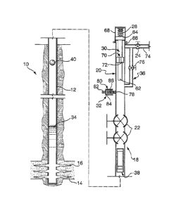
Referring now to Figures 1 and 2, a hydrocarbon well 10 comprises a wall 12
extending into the
earth may be in communication with a subterranean hydrocarbon bearing
formation 14. The
wall 12 is typically defined by the inner diameter of a conventional tubing
string made up of
joints of tubing that are threaded together. The wall 12 may be the inside of
a casing string, a
tubing string, a production string, etc. The formation 14 communicates with
the inside of the
well through perforations 16. As will be more fully apparent hereinafter, the
plunger lift system
may be used to lift formation liquid 34 from the bottom of the well 10 which
may be either an oil
or a gas well.
In one embodiment of the present invention, the well 10 is a gas well that
produces some
formation liquid 34 that may be contained in a column at the lower portion of
the wellbore and
further found along the walls of the wellbore. In an earlier stage of the
productive life of the well
10, there is sufficient gas being produced to deliver the formation liquids to
the surface. The
well 10 is equipped with a conventional well head assembly 20, for example,
comprising a pair
WSLegaI\027030\00105`, 6042910v3 6
CA 02705086 2010-05-21
of master valves 22 and a wing valve 24 delivering produced formation products
to a surface
facility for separating, measuring and treating the produced products.
One embodiment of the present plunger lift invention may comprise, as major
components, a
piston 26 (Figure 2), including in this embodiment a ball plug 40 and a sleeve
38, an upper
bumper 28, a decoupler 30, a catcher assembly 32, and a bypass 36 around the
piston 26 when it
is its uppermost position in the well head assembly 20 (Figure 1).
As noted, in one embodiment the piston 26 may be of multi-part construction
including an upper
sleeve 38 and a plug, for example a ball 40. The sleeve 38 comprises a tubular
body 42 having a
central passage 44, a fishing lip 46 at the upper end thereof and an annular
seating surface 48 at
the lower end thereof sized to closely receive the ball 40. In other words,
the seating surface 48
may generally define a concave surface, for example a portion of a concave
spherical surface and
has a radius of curvature substantially matching that of the plug 40. The
seating surface 48 may
be recessed or nested into the sleeve 38 so that the ball 40 fits up into the
sleeve 38, when in the
seated position. The main reason is that when the sleeve 38 contacts the plug
40 at the bottom of
the well, the ball 40 is overlapped and retained by the sleeve.
The exterior of the sleeve 38 provides a seal arrangement 50 to minimize fluid
on the outside of
the sleeve 38 from bypassing around the exterior of the sleeve 38. The seal
arrangement 50 may
be of any suitable type, such as elastomeric ring, wire wound around the
sleeve, a multiplicity of
bristles or the like or may, as shown, comprise a series of simple grooves or
indentations 52.
The grooves 52 work because they create a turbulent zone between the sleeve 38
and the wall 12
thereby restricting fluid flow on the outside of the sleeve 38. The grooves 52
may also be used
as a catch area for a retriever to hold the sleeve 38 at a well head, as will
be more fully apparent
hereinafter.
As another example, a plurality of pads 252 encircling a sleeve 238 may be
employed (Figure 4).
The pads 252 may be retained by upper 254 and lower 256 retaining rings. The
retainer rings
may enable pads 252 to float between the rings and the outer surface of the
sleeve body. The
pads 252 may be biased away from the sleeve body. In another example, there
may be an
elastomeric, for example rubber, seal 258 that encircles the body of sleeve
238 beneath pads 252.
W S Lega I\027030\00105 6042910v3 7
CA 02705086 2010-05-21
Seal 258 may assist in biasing pads 252 radially outwardly and prevent any
wellbore fluids from
being trapped between sleeve 238 and pads 252.
The ball 40 may act as a plug to seal passage 44 through the sleeve, when the
ball and the sleeve
are in a united position. The ball may have a radius of curvature
substantially matching the
seating surface 48. By suitably machining the ball 40 and surface 48, no
resilient seals or
additional seals of any type may be necessary. The seating surface 48 may be
machined to a
clean finish or no special surface preparation may be performed. After a few
impacts with the
ball 40, the seating surface 48 may assume a desirable surface finish.
The plug may be fully separable from the sleeve or alternatively, the plug may
be loosely
attached to the sleeve. For example, the plug may be a ball or a dart that is
fully separable from
the sleeve to move independently therefrom. In another embodiment, the plug
may be tethered
to the sleeve. For example, the plug may be a connected part such as a spear
that includes a plug
end and a retainer that holds the plug loosely adjacent the sleeve passage,
such that it can move
into or out of a united position in the passage but cannot fully separate from
the sleeve.
As will be more fully apparent hereinafter, the ball 40 may be released, for
example launched or
dropped into the well 10 so that the ball travels to the column of formation
liquids in the lower
portion of the wellbore. Following which, the sleeve 38 may be released. The
ball 40 and sleeve
38 accordingly may fall independently into the well 10, usually while the well
10 is producing
gas and liquid which flows upwardly through the well head assembly 20. By
independently, it is
meant that the ball 40 is not seated in the sleeve 38 and the ball 48 and the
sleeve 38 are capable
of moving to some degree independently of one another even if they are
tethered or connected
together in some fashion. When the ball 40 and sleeve 38 reach the bottom of
the well, they nest
together with ball 40 united in seat 48 in preparation for moving upwardly. In
particular, the ball
may be stopped first and the sleeve lands above and possibly on the ball and
the ball moves into
a united position in area 48 to complete the piston and form a piston face.
In one embodiment, the sleeve 38 and ball 40 each may have a flow bypass so
they separately
fall easily into the well 10 even when there is substantial upward flow in the
production string
12. When they reach the bottom of the well, they may align into the united
position of a single
component which substantially closes the flow bypasses, or at least restricts
them, so gas
WSLegal\027030\00105\ 6042910v3 8
CA 02705086 2010-05-21
entering through the perforations 16 may push the piston 26 upwardly in the
well and thereby
carry any liquid, at least in the sleeve, upwardly toward the well head
assembly 20.
Looked at in another perspective, the sleeve 38 and ball 40 each have a
surface area which is
selected so that they independently fall in the well but, when they are united
into the piston, they
form a piston face such that the piston is pushed upwardly in the well thereby
carrying any liquid
retained within the central passage sleeve upwardly toward the well head
assembly 20. The
selection of the surface areas of the sleeve 38 and ball 40 may be done so
that a given pressure
differential will move the ball 40 before moving the sleeve 38. In other
words, the ball 40 may
be easier to move than the sleeve 38. The reason is that if the ball 40 can be
constructed so it
always pushes from below, there is no tendency for the sleeve 38 to separate
from the ball 40
during upward movement in the well 10.
The upper bumper 28 and decoupler 30 may be of any conventional designs and
are well known
in the plunger lift art and are commercially available.
The upper bumper 28 acts to stop upward progress of the piston in the wellhead
and the
decoupler 30 acts to separate the piston when it reaches the well head
assembly 20. The
decoupler 30 in one embodiment comprises a rod 62 sized to pass into the top
of the sleeve 38
and is fixed to a piston 64. The piston 64 is larger than a conduit 66 in
which the rod 62
reciprocates and is, thus, prevented from falling into the well 10. The top of
the well head
assembly 20 is closed with a screw cap 68. A stop 70 on the rod 62 limits
upward movement of
the sleeve 38. A series of grooves 72 allow formation products to pass around
the stop 70 and
into a flow line 74 connected to the wing valve 24. It will be seen that the
piston moves
upwardly in the well 10 as one piece. When the sleeve 38 passes onto the end
of the rod 62, the
rod ultimately contacts the top of the ball 40, stopping upward movement of
the ball 40 and
allowing continued upward movement of the sleeve 38. The end of the rod 62
below the stop 70
is longer than the passage 44 so the ball 40 is pushed out of the sleeve 38
thereby releasing the
ball 40 which falls toward the bottom of the well 10.
The bypass 36 may help prevent the piston 26 from sticking in the well head
assembly 20 and
may include a valve 76. The bypass 36 opens into the well head assembly 20
below the bottom
of the sleeve 38 when it is in its uppermost position in the well head
assembly 20. Thus, there
WSLegal\027030\00105\ 6042910v3 9
CA 02705086 2010-05-21
will be a tendency of gas flowing through the well head assembly 20 to move
through the bypass
36 rather than pinning the sleeve 38 against the stop 70.
A catcher 32 may be provided to latch onto the sleeve 38 and thereby hold it
for a while to
provide a delay period or lag between successive cycles of the piston in an
attempt to match the
cycle rate of the piston with the well 10 to remove produced formation liquid
as expeditiously as
possible and thereby restrict gas production as little as possible. To these
ends, in the present
illustration, grooves 52 of the sleeve 38 are sized to receive a ball detent
78 forced inwardly into
the path of the sleeve 38 by an air cylinder 80 connected to a supply of
compressed gas (not
shown) through a fitting 82. A piston 84 in the cylinder 80 is biased by a
spring 86 to a position
releasing the ball detent 78 for movement out of engagement with one of the
slots 52. Pressure
is normally applied to the cylinder 80 thereby forcing the ball detent 78 into
the path of travel of
the sleeve 38. Upon a signal from a controller (not shown), gas pressure is
bled from the
cylinder 80 allowing the spring 86 to retract the piston 84 and allowing the
weight of the sleeve
38 to push the ball detent 78 out of the slot 52 thereby releasing the sleeve
38 for movement
downwardly into the well 10.
When it is desired to retrieve the ball 40 or the sleeve 38, the decoupler 30
is replaced with a
similar device having a stop 70 but eliminating the rod 62. This causes the
sleeve to impact the
bumper 28 without dislodging the ball 40. The piston is held in its upward
position by the flow
of formation products around the piston in conjunction with the catcher 32
which latches onto
the sleeve 38.
Operation of the plunger lift of one embodiment of the present invention
should now be
apparent. The ball 40 is first dropped into the well 10. When the ball nears
the bottom of the
well, it may fall into formation liquid near the bottom of the well but due to
being formed, at
least partially, of a buoyant material the ball may occupy a substantially
floating position, for
example floating completely upon the formation liquids or floating partially
or completely
submerged within the formation liquid. This may cushion any impact of the ball
as it reaches the
bottom of the well and prevent the ball from sinking fully in the liquid in
the well. When the
sleeve 38 is released by the catcher 32, the sleeve will fall and reach the
ball, they will align into
a united position, for example into a single piston face that has a cross-
sectional area comparable
WSLegal\027030`\.OO105\ 6042910v3 10
CA 02705086 2010-05-21
to the inner diameter of the well in which it is used, i.e. any gas entering
the production string
from the formation under the piston is blocked from passing around the piston
and pushes it
upwardly, thereby lifting the piston and any liquid accumulated by the piston
upwardly in the
well to the surface. Liquid retained by the piston will be that amount above
the plug when the
fluid pressure from below begins to move the united piston upwardly, and
generally will be that
amount trapped in the sleeve above the plug. As the piston moves upwardly in
the well, certain
amounts of liquid may also be accumulated from the wellbore walls and may be
pushed ahead of
the piston. Because ball 40 easily enters the bottom opening of the sleeve 38,
the ball 40 and
sleeve 38 easily unite with the ball 40 sealing against the seating member 48.
The combined
downwardly facing surface area of the sleeve 38 and ball 40, in their united
configuration, is
sufficient to allow gaseous products from the formation 14 to push the united
parts 38, 40
forming the piston, and any liquid above the ball, upwardly to the well head
assembly 20.
As the piston approaches the well head assembly 20. The sleeve 38 passes over
the rod 62 which
stops upward movement of the ball 40 thereby releasing the ball 40 which drops
into the well 10
in the start of another cycle. The sleeve 38 is retained by the catcher 32 at
least momentarily
longer and maybe for a period of time depending on the requirements of the
well 10. If the well
10 needs to be cycled as often as possible, the delay provided by the catcher
30 is only long
enough to be sure the ball 40 is unseated from the sleeve 38. In more normal
situations, the
sleeve 38 will be retained on the catcher 30 so the piston 26 cycles only when
desired.
While previous pistons formed of metal have proved quite successful in a wide
variety of
applications, wells having very low bottom hole flowing pressures, e.g. 75
psi, present an
unusually tough situation for any type of plunger lift for a variety of
reasons, almost all of which
relate to the fact that very little liquid will kill the well.
For purposes of illustration, assume that a well has a 75 psi bottom hole
flowing pressure and
fifty feet of liquid in the bottom of the hole above the perforations when the
plunger piston
arrives. A prior art plunger lift might be unable to address such a well
condition. In particular,
when a prior art piston arrives at the bottom of the hole, it will sink until
it is stopped, for
example by a bottom bumper, which is generally positioned below the
perforations. When the
piston starts up the hole, in response to bottom hole flowing pressure under
the piston, it will
WSLegal\027030`,001051 6042910v3 11
CA 02705086 2010-05-21
attempt to lift the entire fifty foot column of liquid plus any liquid that
has been sheared off
during downward movement of the sleeve plus any liquid that is picked up
during upward
movement of the piston. Because the bottom hole flowing pressure is so low, it
is easy to collect
enough liquid above the piston, to slow down and stop the piston or to prevent
it ever from
starting up the well. When this occurs, the piston ultimately falls to or
remains at the bottom and
the well is dead.
It has been found that by forming the ball 40 and possibly also the sleeve 38
of a material
capable of floating to some degree in formation liquids, for example oil,
condensate, water or a
mixture thereof, the volume of fluid attempted to be carried by the piston to
surface can be
controlled to prevent the weight of the fluid column above the piston from
overcoming and
stopping movement of the piston. If the sleeve is multi part, and it is
intended have some
buoyancy, as shown in Figure 4, some or all sleeve components can be made of
buoyant
materials. For example in Figure 4, both the tubular body of the sleeve and
the pads may be
formed of buoyant materials.
In one embodiment, for example, the ball 40 may be formed of a buoyant
material such that the
ball is buoyant to some degree in wellbore fluids. For example, the buoyant
material may have a
specific gravity of about I or less, where the specific gravity of water is 1.
The specific gravity
of hydrocarbons (such as condensate or oil) is lower than water and this may
have to be
considered if the formation liquids are high in hydrocarbons. Therefore,
depending upon the
constituents of the formation liquids, the buoyant material may have a
specific gravity of less
than 1:1 with the formation liquids within the well. Examples of buoyant
materials may include
wood, substantially buoyant polymers for example phenolics such as polyphenols
and high
density polyethylene, foamed materials, hollow materials, etc. Of course
durability of the
material in well bore conditions and impact resistance must also be
considered. However, since
the ball and sleeve cycle to surface regularly their condition can be
monitored occasionally and
replacement or repair can be carried out if necessary.
In another embodiment, where it is useful to detect the position of the
piston, for example
magnetically, it may be beneficial to include a metal portion on the body of
the piston. For
example, the piston may be made of buoyant materials and the retainer bands,
as shown in Figure
WSLegal\027030\00105\ 6042910v3 12
CA 02705086 2010-05-21
4, may be made of metal, provided overall the piston is capable of
substantially floating in
formation liquids.
Sleeve 38 may formed to sit on the ball and, so, can be selected to be
retained in a substantially
floating condition by the ball or can itself be formed of a buoyant material
similar to, or different
from, the ball. For example, in one embodiment the ball can be at least
partially formed from
materials that are more buoyant in the formation liquids than the materials of
the sleeve. In this
embodiment, the greater buoyancy of the ball, relative to the sleeve, may
assist in creating a
tighter seal at the seating surface when the ball and the sleeve unite.
The buoyancy of at least the ball acts to limit the degree to which the ball
can sink in the fluid
column and limit the volume of water to be carried by the piston. In
particular, the ball after
hitting the liquid will be urged by its buoyancy into a substantially floating
position in the
formation liquid column. The sleeve when it lands will momentarily receive
liquid into passage
44, but will quickly settle into position united with ball 40, wherein ball 40
is seated in sleeve 38.
A volume of liquid V can move into passage 44 through upper end 42, as when
the sleeve drops
below surface or by splash, or through the sleeve's lower end before the ball
is seated in the
passage. When ball 40 seals against seat 48 and formation pressures begin to
act from below the
ball, any liquid accumulated in passage 44 is trapped therein.
The volume of liquid carried to surface may be defined by the volume defined
in passage 44
between upper end 46 and ball 40 and the depth at which the piston floats
below surface, if at all,
before beginning uphole. However, while travelling uphole, the piston may
accumulate more
fluids from the wellbore walls. The piston can cycle rapidly to unload the
well and can allow
unloading even in low production and large diameter wells where production
flow may limit the
usefulness of prior art plunger lifts.
In addition to the controlled and more readily liftable volume of liquid
handled by the piston, the
buoyancy acts as a shock absorber and bottom stop for the piston. Also, there
is no need to
install a bottom bumper in the well.
Also, surface facilities needn't be equipped to handle large plugs of
formation liquid.
WSLegal\027030\00105\ 6042910v3 13
CA 02705086 2010-05-21
In another embodiment, a piston 126 may be of one piece construction, wherein
the sleeve 138
has a closed bottom that forms a piston face 140 (see Figures 5 and 6). In
particular, sleeve 138
comprises a tubular body 142 having a central passage 144 extending from an
open upper end
146 and closed at its bottom end by an end wall 145 to form the piston face
140. Because the
piston face is integral with the sleeve, as one single piece, there may not be
a necessity for a
decoupler and a catcher, as herein described above. It may be that piston 126
does not have any
flow bypasses and it may be necessary to attenuate or stop the uphole flow of
fluids, such as
formation gas in order to allow the piston to move downhole. The wellhead
assembly may be
actuated, using techniques familiar to those skilled in the art, to
temporarily shut-in the well so
that the piston 126 may fall downhole.
Piston 126 may be formed, in whole or in part, from buoyant materials as
described herein
above. Further, piston 126 may have a fish lip 146 substantially towards open
upper end.
When piston 126 reaches the formation liquids it may occupy a substantially
floating position, as
described herein above, within the column of formation liquids, accumulating
formation liquids
within the central passage 144 in a fashion similar to the accumulation of
formation liquids in
passage 44 as described herein above.
When desired, the operator may actuate the wellhead assembly to open the well
so that formation
gas pressure may be free to push piston 126, and the formation liquids
accumulated therein,
uphole. Further, piston 126 may accumulate liquids from the wellbore walls
while travelling
uphole. An upper bumper of any conventional designs and are well known in the
plunger lift art
may be employed.
The previous description of the disclosed embodiments is provided to enable
any person skilled
in the art to make or use the present invention. Various modifications to
those embodiments will
be readily apparent to those skilled in the art, and the generic principles
defined herein may be
applied to other embodiments without departing from the spirit or scope of the
invention. Thus,
the present invention is not intended to be limited to the embodiments shown
herein, but is to be
accorded the full scope consistent with the claims, wherein reference to an
element in the
singular, such as by use of the article "a" or "an" is not intended to mean
"one and only one"
unless specifically so stated, but rather "one or more". All structural and
functional equivalents
WS1_ega1\027030\00105\ 6042910v3 14
CA 02705086 2010-05-21
to the elements of the various embodiments described throughout the disclosure
that are known
or later come to be known to those of ordinary skill in the art are intended
to be encompassed by
the elements of the claims. Moreover, nothing disclosed herein is intended to
be dedicated to the
public regardless of whether such disclosure is explicitly recited in the
claims. No claim element
is to be construed under the provisions of 35 USC 112, sixth paragraph, unless
the element is
expressly recited using the phrase "means for" or "step for".
W SLegal\027030\00105`. 60429100 15