Note: Descriptions are shown in the official language in which they were submitted.
CA 02705347 2010-05-10
WO 2009/121143 PCT/AU2009/000409
- 1 -
A FAULT CURRENT LIMITER
FIELD OF THE INVENTION
[001] The present invention relates to a fault current limiter.
[002] The invention has been developed primarily for a high voltage saturated
core
fault current limiter and will be described with reference to that
application.
However, the invention is not limited to that particular field of use and is
also suitable
for low voltage, medium voltage, extra-high voltage and ultra-high voltage
fault
current limiters.
BACKGROUND OF THE INVENTION
[003] Saturated core fault current limiters (FCLs) are known. Examples of
superconducting fault current limiting devices include:
= US Patent 7193825 to Darmann et al.
= US Patent 6809910 to Yuan etal.
= US Patent 7193825 to Boenig.
= US Patent Application Publication Number 2002/0018327 to Walker et al.
[004] The fault current limiters described are for use with dry insulation
type copper
coil arrangements and, in practical terms, only suitable for DC saturated FCLs
which
employ air as the main insulation medium. That is, the main static insulation
medium
between the AC phase coils in a polyphase FCL and between the AC phase coils
and
the steel core, DC coil, cryostat, and main structure is provided by a
suitable distance
in air. This substantially limits the FCL to a "dry type" insulation
technologies. Dry
type technologies normally refers to those transformer construction techniques
which
employ electrically insulated copper coils but only normal static air and
isolated solid
insulation barrier materials as the balance of the insulation medium. In
general, air
forms the majority of the electrical insulation material between the high
voltage side
and the grounded components of the FCL. These grounded components include the
steel frame work and the case.
[005] The utilisation of dry type insulation limits the FCL to lower voltage
ranges of
AC line voltages of up to approximately 39 kV. Dry type transformers and
reactors
are only commercially available up to voltage levels of about 39 kV. As a
result, the
current demonstrated technology for DC saturated FCL's is not suitable for
extension
into high voltage versions. Dry type designs result in an inability to design
a
CA 02705347 2010-05-10
WO 2009/121143
PCT/AU2009/000409
- 2 -
practically sized compact structure using air as an insulation medium when
dealing
with higher voltages.
[006] One of the main emerging markets for FCL's is the medium to high voltage
(33 kV to 166 kV) and extra-high voltage range (166 kV to 750 kV). When
operating
within these voltage ranges, the currently described art and literature
descriptions of
DC saturated FCL's are not practical. The main reason is due to static voltage
design
considerations ¨ for example, the breakdown of the air insulation medium
between
the high voltage copper coils and the cryostat or steel core or DC coil. High
voltage
phase coils at medium to high voltages (greater than 39 kV) often need to be
immersed in one of:
= An insulating gas (such as SF6, nitrogen, or the like).
= A vacuum (better than 10 mbar).
= A liquid such as a synthetic silicone oil, vegetable oil, or other
commonly
available insulating oils used in medium, high voltage, and extra-high voltage
transformer and reactor technology.
[007] When a high voltage device is immersed in such an insulating medium,
that
medium is often referred to as the "bulk insulation medium" or the
"dielectric".
[008] Typically, the dielectric will have a relative permittivity of the order
of about 2
to 4, except for a vacuum which has a relative permittivity equal to 1. These
so called
dielectric insulation media have electrostatic breakdown strength properties
which are
far superior to that of atmospheric air if employed judiciously by limiting
the
maximum distance between solid insulation barriers and optimising the filled
dielectric distance with respect to the breakdown properties of the particular
liquid or
gaseous dielectric.
[009] The commonly available bulk insulating gases and liquids typically have
a
breakdown strength in the order of 10 to 20 kV/mm but are usually employed
such
that the average electric field stress does not exceed about 6 to 10 kV/mm.
This
safety margin to the breakdown stress value is required because even if the
average
electrostatic field stress is 6 to 10 kV/mm, the peak electrostatic field
stress along any
isostatic electric field line may be 2 to 3 times the average due to various
electrostatic
field enhancement effects.
CA 02705347 2010-05-10
WO 2009/121143 PCT/AU2009/000409
- 3 -
[0010] In general, there are five main desirable requirements of a dielectric
liquid or
gas for high voltage bulk insulation requirements in housed plant such as
transformers
and reactors and fault current limiters:
= The dielectric must show a very high resistivity.
= The dielectric losses must be very low.
= The liquid must be able to accommodate solid insulators without
degrading that solid insulation (for example, turn to turn insulation on coil
windings or epoxy).
= The electrical breakdown strength must be high.
= The medium must be able to remove thermal energy losses.
[0011] Solid insulation techniques are not yet commonly available at medium to
high
voltages (that is, at operating voltages greater than 39 kV) for housed
devices such as
transformers, reactors and fault current limiters. The shortcoming of solid
insulation
techniques is the presence of the inevitable voids within the bulk of the
solid
insulation or between surfaces of dissimilar materials such as between coil
insulation
and other solid insulation materials. It is well known that voids in solid
insulation
with high voltages produce a high electric stress within the void due the
field
enhancement effect. This causes physical breakdown of the surrounding material
due
to partial discharges and can eventually lead to tracking and complete device
failure.
[0012] It will be recognized that a DC saturated fault current limiter which
employs a
single or multiple DC coils for saturating the steel core, such as those
disclosed in the
aforementioned prior art, poses fundamental problems when the copper AC phase
coils can no longer be of a "dry type" construction or when the main
insulation
medium of the complete device is air. A significant problem in such
arrangements is
the presence of the steel cryostat for cooling the DC HTS coil and the DC FITS
coil
itself The cryostat and the coil and the steel cores are essentially at ground
potential
with respect to the AC phase coils.
[0013] As a side issue, but one which enhances the insulation requirements for
all
high voltage plant and equipment, it is that basic insulation design must also
meet
certain electrical engineering standards which test for tolerance to various
types of
over-voltages and lighting impulses over predetermined time periods. An
example, in
Australia, of such standards are as follows:
CA 02705347 2010-05-10
WO 2009/121143
PCT/AU2009/000409
- 4 -
= AS2374 Part3. Insulation levels and dielectric tests which includes the
power frequency (PF) and lightning impulse (LI) tests of the complete
transformer.
= AS2374 Part 3.1. Insulation levels and dielectric tests ¨ External
clearances in air.
= AS2374 Part 5. Ability to withstand short-circuit.
[0014] These standards do not form an exhaustive list of the standards that
high
voltage electric equipment must meet. It is recognised that each country has
their
own standards which cover these same design areas and reference to an
individual
country's standard does not necessarily exclude any other country's standards.
Ideally a device is constructed to meet multiple countries standards.
[0015] Adherence to these standards result in a BIL (Basic Insulation level)
for the
device or a "DIL" (Design Insulation Level) which is usually a multiple of the
basic
AC line voltage. For example, a 66 kV medium voltage transformer or other
housed
device such as a FCL may have a BIL of 220 kV. The requirement to meet this
standard results in a static voltage design which is more strenuous to meet
practically
than from a consideration of the AC line voltage only. The applicable
standards and
this requirement has resulted from the fact that a practical electrical
installation
experiences temporary over voltages which plant and devices may experience
within
a complex network, for example lightning over voltages, and switching surges.
Hence, all equipment on an electrical network has a BIL or DIL appropriate for
the
expected worst case transient voltages.
[0016] An initial consideration of the static design problem for high voltage
DC
saturated fault current limiters may result in the conclusion that the problem
is easily
solved by housing only the high voltage AC copper coils in a suitable
electrical
insulating gas or liquid. However, the problem with this technique is that the
steel
core must pass through the container which holds the gas or liquid. Designing
this
interface for long term service is difficult to solve mechanically. However,
more
importantly solving the interface problem electrostatically is much more
complex and
any solution can be prone to failure or prove uneconomical. The problem is
that as a
seal must be developed between the vessel containing the dielectric fluid and
the high
permeability core or, alternatively, a method of isolating the HIS cryostat
from the
fluid.
CA 02705347 2010-05-10
WO 2009/121143
PCT/AU2009/000409
- 5 -
[0017] Another possibility is the use of solid high voltage barriers between
phases
and between phases and the steel core and cryostat or a layer of high voltage
insulation around the copper phase coils and in intimate contact with the
phase coils.
However, this has a significant deleterious side effect. It is known that the
static
electric field in a combination of air and other materials with a higher
relative
permittivity is that this always results in an enhanced electric field in the
material or
fluid with the lower permittivity (that is air). For example, consider a
conductive
copper cylinder with a layer of normal insulation to represent the turn to
turn
insulation, according equation 1:
U.
E _________________________
In [¨d I
ini--]
R
1
Equation 1
where:
= Um = AC phase voltage with respect to ground.
= R = radius of a copper cylinder including outside insulation [mm].
= r = radius of bare copper cylinder [mm].
= d = distance from centre of cylinder to the nearest ground plane [mm].
= 62 = relative dielectric constant of the insulation covering the cylinder
= ci = relative dielectric constant of the bulk insulation where the
cylinder is
immersed (which equals 1 for air).
= x = distance from the centre of cylinder to a point outside the cylinder
[mm].
= Ex = Electrostatic field gradient at point x [kV/mm].
[0018] The field enhancement effect is represented by the factor eget and is
of the
order 2 to 4 for common everyday materials except for the case of employing a
vacuum which has a relative permittivity equal to 1. By providing additional
solid or
other insulation material (of higher electric permittivity than air) there is
an increase
in the electrostatic stress in the bulk air insulation of the FCL. The better
the quality
of the high voltage insulation, the higher the field enhancement effect.
[0019] Hence, solid dielectric insulation barriers in an otherwise air
insulated FCL are
not a technically desirable option for high voltage FCL's at greater than 39
kV and
CA 02705347 2010-05-10
WO 2009/121143 PC
T/AU2009/000409
- 6 -
indeed one does not see this technique being employed to make high voltage dry
type
transformers at greater than 39 kV for example. In fact, no techniques have
been
found highly suitable to date and that is why high voltage transformers above
39 kV
are insulated with a dielectric liquid or gas.
[0020] The discussion above is the reason why housed high voltage electrical
equipment is often completely immersed in electrically insulating dielectric
fluid or
gas. That is, the insulated copper coils and the steel core of transformers
and reactors
are housed within a container that is then completely filled with a dielectric
medium
which is a fluid. This substantially reduces the electrostatic voltage design
problems
detailed in the above discussion. The insulating medium (for example oil,
vacuum, or
SF6) fills all of the voids and bulk distances between the high voltage
components and
the components which are essentially at ground or neutral potential. In this
case, solid
insulation barriers may be incorporated into the bulk insulating dielectric
and for
many liquids such as oil, dividing the large distances with solid insulation
improves
the quality of the overall electrostatic insulation by increasing the
breakdown field
strength of the dielectric fluid. This is because the relative permittivity of
the oil and
solid insulation are very close to each other (so field enhancement effects
are lessened
compare to air) and the breakdown voltage of the bulk dielectric medium
(expressed
in kV/mm) improves for smaller distances between the insulation barriers.
[0021] A major problem with the full immersion technique is that it is not
readily
adaptable to a DC saturated FCL designs or other devices that incorporated a
superconductor coil as the DC saturating element. This is
because the
superconducting coil and its cryostat or vacuum vessel are a component of the
FCL
which must also necessarily be immersed in the dielectric fluid.
[0022] The established body of literature clearly points to four main criteria
for a
marketable, feasible, and manufacturable FCL:
= It must have a low insertion impedance so that it is invisible to the
network
when there are no faults and when providing peak power flow.
= It must not produce more than 0.5% THD worth of harmonics (Total
harmonic distortion) or as required by the end user.
= It must provide a suitable clip of the fault current, between 20 to 80%.
= The design must be augmentable to high AC voltages (greater than 6 kV)
and high AC current (greater than 0.6 kA).
CA 02705347 2010-11-12
- 7 -
[0023] The classic saturable core FCL designs detailed in the prior art suffer
the major
drawbacks of not being suitable for high voltage and high AC current designs.
Both of
these disadvantages originate from the lack of a coolant (other than air)
and/or a liquid or
gaseous dielectric.
[0024] Even if a liquid or gaseous dielectric is employed in the classic
saturable FCL
design, there is still required significant augmentation to allow access to
the cryocooler,
cryostat, and cryostat fittings. In addition, special seals to isolate the
cryostat feed-
throughs (electrical power, electrical signals) from the dielectric have to be
made and
tested.
[0025] In high AC current designs, the cross sectional area of copper required
to conduct
the required electrical current is much higher when considering only an air
cooled design.
It is not unusual for this cross section area to be up to five times higher.
This can make
the dimensions of the AC coil too large to be accommodated into the minimum
core
frame yoke size, requiring a larger yoke to maintain electrostatic clearance.
This
increases the footprint and mass of the classic air cooled / air insulated
saturable FCL.
[0026] Any discussion of the prior art throughout the specification should in
no way be
considered as an admission that such prior art is widely known or forms part
of common
general knowledge in the field.
SUMMARY OF THE INVENTION
[0027] It is an object of the preferred embodiments of this invention to
ameliorate one or
more of the aforementioned disadvantages or to provide a useful alternative.
[0028] It is another object of the preferred embodiments of the invention to
overcome one
or more of the above-stated disadvantages by inverting the conventional
relative locations
of the AC and DC coils with an FCL. These embodiments allow the complete
structure
to be immersed in a dielectric.
[0029] According to a first aspect of the invention there is provided a fault
current limiter
for incorporation into an electrical circuit, said fault current limiter
including a
magnetically saturable core and at least one AC phase coil wound around a
portion of
said saturable core wherein said magnetically saturable core and said at least
one AC
phase coil are housed within an enclosure and a DC biasing coil is disposed
outside of
and surrounding said enclosure which during no fault operating conditions of
said current
limiter biases said core into magnetic saturation for low insertion impedance
but during
CA 02705347 2010-11-12
- 8 -
fault conditions takes said core out of magnetic saturation to thereby provide
an increased
current limiting impedance in said electrical circuit.
[0030] In an embodiment, the high permeability core is selected from one or
more of a
transformer steel lamination material; a mild steel; or other forms of
magnetic steel,
ferrite materials or a ferromagnetic material.
[0031] In an embodiment, the core is in the form of a rectangular array of
core posts with
AC phase coils wound one each on respective ones of the core posts and
electrically
interconnected in a manner such that the senses of the magnet fields produced
by the AC
coils are opposing.
[0032] In an embodiment, the fault current limiter includes a vessel
surrounding the AC
coils for containing a dielectric insulation medium and cooling medium for
said AC coils.
[0033] In an embodiment, the DC coil is a superconductor and more preferably a
high
temperature superconductor housed in a cryostat and cooled by a cryocooler.
[0034] In an embodiment, the DC biasing coil is coincident with a coaxial with
the AC
phase coils so that said portion of the saturable core is fully saturated.
[0035] In an embodiment, the magnetically saturable core and AC coils are
immersed in a
dielectric which is in the form of a solid, liquid or gas and including air at
any atmosphere
including vacuum.
[0036] In an embodiment, the core posts are rectangular in cross-section and
of constant
cross-section along the lengths thereof.
[0037] In an embodiment, the magnetically saturable core is constructed from a
transformer steel lamination material, mild steel or other magnetic steel,
ferrite material,
an insulated high permeability compressed powder, or a ferromagnetic material.
[0038] In an embodiment, the core posts are tapered toward the ends thereof
whereby
during no fault operation of the current limiter substantially all of said
core is saturated.
[0039] According to a second aspect of the invention there is provided a fault
current
limiter including:
an input terminal for electrically connecting to a power source that provides
a
load current;
an output terminal for electrically connecting with a load circuit that draws
the
load current;
a magnetically saturable core;
CA 02705347 2012-07-20
9
an AC coil wound about a longitudinal portion of the core for carrying the
load
current between the input terminal and the output terminal;
an enclosure for housing the magnetically saturable core and AC coil; and
a DC coil disposed outside of and surrounding the enclosure for inducing a
magnetic field in at least the portion of the core and extending about a
longitudinal
intermediate zone that receives the core and the AC coil, wherein the field
magnetically
biases the core such that the AC coil moves from a low impedance state to a
high
impedance state in response to one or more characteristics of the load
current.
[0040] In an embodiment, in the low impedance state, the portion is
magnetically
saturated.
[0041] In an embodiment, in the low impedance state, the core is magnetically
saturated
longitudinally beyond the portion.
[0042] In an embodiment, in the high impedance state, the portion is out of
magnetic
saturation.
[0043] In an embodiment, in the low impedance state, the impedance of the AC
coil is
substantially equal to the theoretical air core impedance of the AC coil.
[0044] In an embodiment, one of the one or more characteristics is an increase
of the load
current beyond a predetermined current value.
[0045] In an embodiment:
the core includes a plurality of posts;
the longitudinal portion is segmented between the posts; and
the AC coil includes a plurality of coil segments that are wound about
respective
posts.
[0046] In an embodiment, the posts are parallel.
[0047] In an embodiment, the posts extend longitudinally.
[0048] In an embodiment, each post has a substantially uniform transverse
cross-section.
[0049] In an embodiment, the posts have substantially like transverse cross-
sections.
[0050] In an embodiment, the transverse cross-section of the posts has at
least one axis of
symmetry.
[0051] In an embodiment, the transverse cross-sections of the posts are
symmetric.
[0052] In an embodiment, the posts substantially co-extend within the
intermediate zone.
[0053] In an embodiment, the posts are spaced apart from each other.
[0054] In an embodiment, the posts extend longitudinally beyond the DC coils.
CA 02705347 2010-11-12
- 10 -
[0055] In an embodiment, the coil segments substantially longitudinally
coextend in the
intermediate zone.
[0056] In an embodiment, the AC coil extends longitudinally beyond the DC
coils.
[0057] In an embodiment, each post extends longitudinally beyond the
respective AC
coil.
[0058] In an embodiment, the load current includes three phases and the fault
current
limiter includes three pairs of input terminals and output terminals for the
respective
phases.
[0059] In an embodiment, the fault current limiter includes six posts arranged
in three
pairs, where each pair of posts is associated with a respective pair of input
and output
terminals for carrying the corresponding phase of the load current.
[0060] In an embodiment, the posts in each pairs of posts are yoked together.
[0061] In an embodiment, each post includes longitudinal ends, and at least
one end of
each posts is yoked to an adjacent end of the other post in the same pair.
[0062] In an embodiment, both ends of each posts are yoked to respective
adjacent ends
of the other post in the same pair.
[0063] In an embodiment, the posts are yoked magnetically and physically by a
high
permeability material.
[0064] In an embodiment, the posts in each pair are adjacent each other and
include
spaced apart opposing faces.
[0065] In an embodiment, the opposing faces are substantially planar.
[0066] In an embodiment, the opposing faces are substantially parallel.
[0067] In an embodiment, the opposing faces are substantially coextensive.
[0068] In an embodiment, the enclosure defines the intermediate zone.
[0069] In an embodiment, the enclosure contains a dielectric material.
[0070] In an embodiment, the AC coil is received within the dielectric.
[0071] In an embodiment, the DC coils each include a high conductivity
material.
[0072] In an embodiment, the high conductivity material is selected from:
copper;
aluminium; a high temperature superconductive material; a low temperature
superconductive material.
[0073] According to a third aspect of the invention there is provided a method
of limiting
current including the steps of:
CA 02705347 2010-05-10 . .
WO 2009/121143 PCT/AU2009/000409
- 11 -
providing an input terminal for electrically connecting to a power source that
provides a load current;
providing an output terminal for electrically connecting to a load circuit
that
draws the load current;
providing a magnetically saturable core;
winding an AC coil about a longitudinal portion of the core for carrying the
load current between the input terminal and the output terminal; and
inducing a magnetic field in at least the portion of the core with at least
one
DC coil, wherein the DC coil extends about a longitudinal intermediate zone
that
receives the core and the AC coil, and wherein the field magnetically biases
the core
such that the AC coil moves from a low impedance state to a high impedance
state in
response to one or more characteristics of the load current.
[0074] According to a fourth aspect of the invention there is provided a fault
current
limiter including:
an input terminal for electrically connecting to a power source that provides
a
load current;
an output terminal for electrically connecting with a load circuit that draws
the
load current;
a magnetically saturable core;
an AC coil wound about a longitudinal portion of the core for carrying the
load current between the input terminal and the output terminal; and
at least one DC coil that is in an open-core arrangement with the AC coil for
inducing a magnetic field in at least the portion of the core, the DC coil
extending
about a longitudinal intermediate zone that receives the core and the AC coil,
wherein
the field magnetically biases the core such that the AC coil moves from a low
impedance state to a high impedance state in response to one or more
characteristics
of the load current.
[0075] According to a fifth aspect of the invention there is provided a method
of
limiting current using a fault current limiter, the method including:
electrically connecting a power source to an input terminal for providing a
load current;
electrically connecting a load circuit to an output terminal for drawing the
load
current;
providing a magnetically saturable core;
CA 02705347 2010-05-10
WO 2009/121143 PCT/AU2009/000409
- 12 -
providing an AC coil wound about a longitudinal portion of the core for
carrying the load current between the input terminal and the output terminal;
and
providing at least one DC coil that is in an open-core arrangement with the AC
coil for inducing a magnetic field in at least the portion of the core, the DC
coil
extending about a longitudinal intermediate zone that receives the core and
the AC
coil, wherein the field magnetically biases the core such that the AC coil
moves from
a low impedance state to a high impedance state in response to one or more
characteristics of the load current.
[0076] According to a sixth aspect of the invention there is provided a fault
current
limiter including:
three input terminals for electrically connecting to respective phases of a
three
phase power source that provides a three phase load current;
three output terminals for electrically connecting with the respective phases
of
a load circuit that draws the load current;
a magnetically saturable core having three pairs of posts, each post having a
longitudinal portion;
three AC coils wound about the portions of respective pairs of posts for
carrying the load current between the input terminals and the output
terminals; and
at least one DC coil for inducing a magnetic field in at least the portions
and
extending about a longitudinal intermediate zone that receives the posts and
the AC
coils, wherein the field magnetically biases the core such that the AC coil
moves from
a low impedance state to a high impedance state in response to one or more
characteristics of the load current.
[0077] In an embodiment, each AC coil includes two coil segments that are each
wound about respective portions of the posts in the pair of posts.
[0078] According to a seventh aspect of the invention there is provided a
method of
limiting current using a fault current limiter, the method including the steps
of:
electrically connecting to respective phases of a three phase power source
three input terminals for providing a three phase load current;
electrically connecting with the respective phases of a load circuit three
output
terminals for drawing the load current;
providing a magnetically saturable core having three pairs of posts, each post
having a longitudinal portion;
CA 02705347 2010-05-10
WO 2009/121143 PCT/AU2009/000409
- 13 -
providing three AC coils wound about the portions of respective pairs of posts
for carrying the load current between the input terminals and the output
terminals; and
providing at least one DC coil for inducing a magnetic field in at least the
portions and extending about a longitudinal intermediate zone that receives
the posts
and the AC coils, wherein the field magnetically biases the core such that the
AC coil
moves from a low impedance state to a high impedance state in response to one
or
more characteristics of the load current.
[0079] According to an eighth aspect of the invention there is provided core
for a
fault current limiter, the core including at least one longitudinally
extending post
having at least two portions that are magnetically saturable and which, in
use, are
received within respective coil segments of an AC coil that, in turn, is
received within
a DC coil.
[0080] In an embodiment, the portions are spaced apart.
[0081] In an embodiment, the core includes two like parallel posts having
respective
portions.
[0082] In an embodiment, the posts are yoked.
[0083] In an embodiment, the posts are yoked to each other.
[0084] In an embodiment, each post extends between a first end and a second
end,
wherein the first end and second end of one of the posts are adjacent to the
first end
and the second respectively of the other post.
[0085] In an embodiment, the core includes a yoke for extending between the
first
ends for yoking the posts to each other.
[0086] In an embodiment, the core includes a further yoke for extending
between the
second ends for yoking the posts to each other.
[0087] In an embodiment, the posts include post laminations.
[0088] In an embodiment, the yokes include yoke laminations.
[0089] In an embodiment, the post laminations and the yoke laminations are
interleaved.
[0090] In an embodiment, the core includes six longitudinally extending posts
arranged in three pairs.
[0091] According to a ninth aspect of the invention there is provided a fault
current
limiter including a core of the eighth aspect of the invention.
CA 02705347 2010-05-10
=
WO 2009/121143
PCT/AU2009/000409
- 14 -
[0092] According to a tenth aspect of the invention there is provided an
electrical
distribution system including at least one fault current limiter of one of the
first,
second, fourth, sixth and ninth aspects of the invention.
[0093] Reference throughout this specification to "one embodiment", "some
embodiments" or "an embodiment" means that a particular feature, structure or
characteristic described in connection with the embodiment is included in at
least one
embodiment of the present invention. Thus, appearances of the phrases "in one
embodiment", "in some embodiments" or "in an embodiment" in various places
throughout this specification are not necessarily all referring to the same
embodiment,
but may. Furthermore, the particular features, structures or characteristics
may be
combined in any suitable manner, as would be apparent to one of ordinary skill
in the
art from this disclosure, in one or more embodiments.
[0094] As used herein, unless otherwise specified the use of the ordinal
adjectives
"first", "second", "third", etc., to describe a common object, merely indicate
that
different instances of like objects are being referred to, and are not
intended to imply
that the objects so described must be in a given sequence, either temporally,
spatially,
in ranking, or in any other manner.
BRIEF DESCRIPTION OF THE DRAWINGS
[0095] Currently preferred embodiments of the invention will now be described
with
reference to the following attached drawings in which:
Figure 1 is a schematic view of a an experimental FCL core structure;
Figure 2 illustrates the results of an FEA analysis on the structure of Figure
1;
Figure 3 illustrates a closed core structure for an FCL with the AC coil and
DC coil being overlayed and coaxial ¨ that is, the two coils are wound about
the same
limb of the closed core;
Figure 4 illustrates an experimental closed core structure with associated
search coils for allowing an investigation of the nature of insertion
impedance;
Figure 5 is an illustration of the results of the experiment conducted with
the
structure of Figure 4;
Figure 6 summarises the measured insertion impedance results for the above
experimental structures;
Figure 7 is a schematic cross-sectional view of a three phase open core fault
current limiter according to said invention;
CA 02705347 2010-05-10
WO 2009/121143 PC T/AU2009/000409
- 15 -
Figure 8 is a schematic view of the electrical interconnection of the windings
on two of the core posts shown in the fault current limiter of Figure 7;
Figure 9 shows FEA analysis results of the magnetic field and relative
permeability across the length of a core in the Z direction of Figure 7;
Figure 10 shows a plot of the magnetic field along a line central to the cores
and crossing three core posts in the X direction of Figure 7;
Figure 11 shows a plot of the magnetic field in the centre of a single core
post
of Figure 7 with DC current energisation;
Figure 12 shows a plot of the DC magnetisation of the core of Figure 7 with
DC minor excursions about two otherwise saturated operating points;
Figure 13 shows a plot of the relative permeability at the middle of a core
post
of Figure 7 with respect to DC coil energisation and with 1,000 amps of
current in the
50 turn AC coil;
Figure 14 shows a plot of the DC magetisation of the core of Figure 7 as a
function of the DC ampere-turns with the full AC current on the AC coil such
that the
fluxes produced by each are opposing;
Figure 15 is an alternative form of the invention showing the same winding
interconnection and that the bottom yoke between two cores is retained;
Figure 16 shows an arrangement of a three phase open core FCL design with
three rows and two columns of steel cores and with electrical interconnections
on
each phase according to that detailed in Figure 8;
Figure 17 shows an alternative arrangement of the three phase open core FCL
design with two rows and three columns of steel cores and with electrical
interconnections on each phase according to that detailed in Figure 8;
Figure 18 shows a yoked alternative of the three phase open core FCL and
with electrical interconnections on each phase according to that detailed in
Figure 8;
Figure 19 shows the experimental arrangement employed for flux density and
AC steady state un-faulted insertion impedance measurements and fault current
limiting characterisation and with electrical interconnections on each phase
according
to that detailed in Figure 8;
Figure 20 shows the measured un-faulted insertion impedance characteristics
for the open core FCL experimental arrangement;
Figure 21 shows the un-faulted steady state insertion impedance
characteristics at different AC voltages and currents;
CA 02705347 2010-05-10
WO 2009/121143 PCT/AU2009/000409
- 16 -
Figure 22 shows Fault current characterisation plots for an open core FCL as a
function of the DC bias;
Figure 23 shows the Flux density transient characterisation plots of the open
core experimental arrangement;
Figure 24 shows a plot of DC circuit transient voltage when the core is
saturated to an extent beyond the AC coil's region of influence, and where the
presence of the fault is detected as a slight drop in voltage between arrow
points
starting from t = 0.08 seconds;
Figure 25 shows the transient fault current plots of the experimental
arrangement with and without the open core FCL in circuit;
Figure 26 shows the DC circuit transient current characteristics of the open
core FCL experimental arrangement;
Figure 27 shows the Experimental arrangement of AC & DC coils for the
measurement and characterisation of the flux density, AC un-faulted insertion
impedance, and fault current limiting ability of the yoked FCL and with
electrical
interconnections on each phase according to that detailed in Figure 8;
Figure 28 shows the measured un-faulted steady state insertion impedance of
the open core yoked FCL experimental arrangement compared to that measured on
the unyoked open core FCL with limbs of the same dimensions;
Figure 29 shows the measured un-faulted insertion impedance comparison
between yoked and unyoked open core arrangements and compared to various
closed
core arrangements;
Figure 30 shows the measured un-faulted steady state insertion impedance of
the open core yoked FCL experimental arrangement compared to that measured on
the unyoked open core FCL with limbs of the same dimensions;
Figure 31 shows the fault current characterisation plots for a yoked open core
FCL as a function of the DC bias;
Figure 32 shows the flux density plot of the open core FCL experimental
arrangement, taken from a search coil around a steel limb and located at the
top of the
AC coil of a yoked open core FCL;
Figure 33 shows the DC circuit transient current characteristics of the yoked
open core FCL experimental arrangement;
Figure 34 is a schematic representation of an FCL in an electrical
distribution
system;
CA 02705347 2012-07-20
- 17 -
Figure 35 is a schematic perspective view of a single phase open core FCL in
which the core includes two steel posts that are stacked end-to-end;
Figure 36 is a top view of the FCL of Figure 35;
Figure 37 is a schematic perspective view of a single phase open core FCL in
which the core includes a single post of pressed power;
Figure 38 is a top view of the FCL of Figure 37;
Figure 39 is a schematic perspective view of a further embodiment of an FCL
having a generally circular footprint and which includes yokes between the
posts
within the core; and
Figure 40 is a schematic top view of the FCL of Figure 39
Figure 41 is a schematic perspective view of an FCL similar to that of Figure
39 sans the yokes;
Figure 42 is a top view of the FCL of Figure 41;
Figure 43 is a schematic perspective view of an FCL that includes a core
having rectangular cross-section posts arranged in a stacked 3 x 2 array;
Figure 44 is a schematic perspective view of an FCL that includes a core
having rectangular cross-section posts arranged in a side-by-side 3 x 2 array;
and
Figure 45 is a schematic perspective view of an FCL that includes a core
having rectangular cross-section posts arranged in a stacked 3 x 2 array which
are
yoked.
DETAILED DESCRIPTION OF THE PREFERRED EMBODIMENTS
[0096] While a number of embodiments are described below, further embodiments
of
the invention are disclosed in Australian Patent Application No. 2009901138
filed on
16 March 2009 and from which priority is claimed.
[0097] The following description with reference to Figures 1 to 6 is intended
to
provide the addressee with context about the embodiments of the invention.
[0098] Firstly, it is mentioned that frequently used parametric features of
the
preferred embodiments include:
= Acme The cross sectional area of the high permeability cores under the AC
coil
= N., : The number of AC turns,
= Nd, : The number of DC turns,
CA 02705347 2010-05-10
WO 2009/121143
PCT/AU2009/000409
- 18 -
= Idc : The DC coil current [Amps],
= lac : The AC coil current [Amps, rms]
= f: The frequency of the electrical system
= Zb : The base impedance of the electrical system that is being protected
= Z+: The positive sequence impedance of the system
= If,: The prospective fault current of the system
= Ifr : The desired reduced fault current
[0099] The fault current limiting and the insertion impedance are functions of
the
above parameters.
[00100] It will be well known to those skilled in the art that
magnetisation of a
high permeability structure as required in the field of FCLs is prone to flux
loss due to
the following two main effects:
= The fringing of the magnetic field lines around the DC bias coil and
returning through a purely air path.
= Partial air/core flux return where the flux enters the core but returns
via an
air path instead of a complete high permeability path.
[00101] For example, an FEA analysis was conducted on the core structure
shown in Figure 1. The relevant characteristics of this core structure are:
= Window dimension width = 290 mm.
= Window dimension height = 350 mm.
= Material: M6 laminated steel core.
= Laminations employed to construct core: 0.35 mm step lapped core
structure.
= Cross sectional area of core: 150 mm x 150 mm.
[00102] Other experimental details are shown in Figure 1 and fuller
results are
shown in Figure 2.
[00103] It was found that there was a loss of magnetic flux density in the
far
limbs and yokes. Table 1 below summarises the results for the Figure 1 core
structure
at the point of maximum flux density.
CA 02705347 2010-05-10
WO 2009/121143 PC
T/AU2009/000409
- 19 -
Table 1: Basic flux density results on prototype core of Figure 1
Search coil number
Location Flux density (T)
employed
Centre of inner limb 6 2.12
Inner limb close to DC coil 5 2.07
Top yoke, close to DC coil 4 2.01
Top yoke further from DC coil 3 2.01
Top of outer limb 2 1.96
Centre of outer limb 1 1.95
[00104] The effect described here is well known to those skilled in the
art. The
reduction in AC core side flux density from 2.12 Tesla to 1.95 Tesla may not
at first
sight seem a disadvantage. However, it is the minor loop measurement on the AC
coil which reveals the problem. While the DC side coil minor loop results in
an
average relative permeability of close to 1.0, as expected for a saturated
core, the
minor loop measured at the same level of DC coil current reveals a relative
permeability of 86. This result in a high insertion impedance for the device
and also
reveals that the AC side core is not fully saturated despite observing the
classic
flattening out of the B-H curve.
[00105] The approaches to reducing flux density loss and keeping the AC
side
of the core saturated include:
= Employing a higher cross sectional area of core throughout the frame.
= Non-uniform cross sections of steel.
= Reducing the total magnetic length of steel between the AC and the DC
coil to make a low profile core structure.
[00106] However, as an alternative to these approaches it is also practical
to
place the AC coils on the near side limbs as shown in Figure 3.
[00107] Using this technique, the flux density in the limbs immediately
underneath the AC coils is substantially the same as that immediately
underneath the
DC coils.
[00108] During steady state operation, the flux from the AC coils must be
such
that the magnetic flux density in the portion of the steel core under
influence is not de-
saturated or changed substantially. For this would lead to higher than the
minimum
CA 02705347 2010-05-10
WO 2009/121143
PCT/AU2009/000409
- 20 -
possible insertion impedance and cause harmonic content in the steady state un-
faulted AC waveform.
[00109] During the fault limiting activity, the flux generated from the AC
coils
negates that in the steel core, de-saturating a portion of the steel core, and
causing the
terminal impedance of the AC coil to rise.
[00110] In this particular arrangement, it will also be recognised that
the
outside yokes and limbs are now no longer required ¨ only the central limbs
are
needed.
[00111] The problem associated with loss of flux density in the limb
containing
the AC coil is also associated with a higher steady state impedance in the un-
faulted
state, also known as the insertion impedance. The insertion impedance
associated
with an AC coil is directly proportional to the gradient of the flux density
versus the
magneto motive force (MMF) graph. If the portion of the core under the
influence of
the AC coil is not fully saturated to a point where this slope is minimised,
then the
insertion impedance will be impractically high.
[00112] To illustrate the nature of insertion impedance an experimental
arrangement was constructed Figure 4 to measure it for various locations of
the AC
coil on a core with respect to the DC coil. A core and coil structure was
constructed
with the details shown in Table 2 and Table 3 below.
Table 2
O.D.Height No. of No. of Resistanc Wire
I.D. (mm) Dia
(mm) (mm) Turns Layers e (Ohms)
(mm)
Search Coils 15 25.5 1 1.70 0.5
DC Coil 160 184 280 171 3 4.0
Former (DC) 150 160 280
Core
650 (H) X 450
Window
(W) mm
Internal Size
Core Section 100 X 100 mm
CA 02705347 2010-05-10
WO 2009/121143
PCT/AU2009/000409
- 21 -
Table 3
Iron Core Fill Factor 0.96
Intergrating flux meter employed Walker Magnet
Flux Meter Settings 25.5 x 0.96 x 100 = 2448
Copper DC Coils Used (No Superconductor)
All Aluminium Construction & Support¨No Mild Steel Employed
Search Coils Directly Wound Tightly On Core
M6 Laminated Steel Core (0.35 mm thick laminations)
[00113] Reference is now made to Figure 5. Confirmation of saturation on
the
DC side was made using search coils and hall probes. The use of Hall probes
necessitated the need to introduce a 1.3 mm air gap in the core which was not
employed during insertion impedance measurements.
[00114] Other details of the experimental arrangement for the measurement
of
insertion impedance include:
= DC current = 100 Amps DC
= AC voltage = 50 V AC
= Frequency of AC voltage and current: 50 Hz
= AC current = 28 Amps AC
= AC turns = 50
= AC coil resistance = 0.10 Ohms
[00115] Figure 6 summarises the measured insertion impedance results. The
minimum insertion impedance is achieved with the coincident coil arrangement
and
with the minimum number of ampere-turns on the DC coil required for
saturation.
All other arrangements, including that where the AC coil is on the same limb
as the
DC coil and in close proximity to the DC coil, result in a higher insertion
impedance.
[00116] Measurements of insertion impedance as a function of ampere-turns
have confirmed that the high permeability core under the influence of the AC
coil
must not only be saturated but must be "super saturated" to have the
theoretical
minimum insertion impedance.
[00117] As shown in Figure 34, the fault current limiter (FCL) is located
in an
electrical distribution substation. The FCL is primarily included to limit the
fault
current of a transformer, which is also illustrated. Where a substation
includes more
than one transformer, it is possible to have a separate FCL for each of those
CA 02705347 2010-05-10
WO 2009/121143
PCT/AU2009/000409
- 22 -
transformers. However, in some embodiments, less than all of the transformers
within a substation have an associated FCL.
[00118] The FCL, on the downstream side, is electrically connected to an
electrical distribution system of which the substation is a part.
[00119] In other embodiments, the transformer and the FCL are located
within
an installation other than a substation. Indicative examples include an
industrial site
distribution network, between a co-generator and the rest of the grid; and
protecting
the main electricity grid from the fault current contribution of a wind farm,
wave
generator, hydro-generator, or solar energy farm.
[00120] For the Figure 34 embodiment, the power station is a coal-fired
power
station. However, in other embodiments, the power station is one or more of a
hydro-
station, a nuclear power station and a wind generator power station.
[00121] Referring to Figure 7 there are illustrated a series of high
permeability
posts 1 in a three phase open core FCL arrangement in accordance with an
embodiment of the invention. The Z direction is defined as being along the
longitudinal direction of the high permeability core as shown. The posts are
manufactured from transformer laminations, and the rolling direction of the
laminations is along the Z axis.
[00122] It will be appreciated that posts 1 collectively define a core for
the
FCL.
[00123] The high permeability posts 1 are of transformer steel lamination
material. In other embodiments, use is made of one or more of mild steel or
other
forms of magnetic steel ferrite materials or ferromagnetic material or
granular
material such as a core made from consolidated ferromagnetic powder, or a
glassy
amorphous core.
[00124] A DC coil 2, for the purposes of saturating a portion of the high
permeability posts 1, surrounds the complete structure outside of the
enclosure. The
term "surrounds" or the like are used to describe how coil 2 encircles the
enclosure or
tank. That is, the DC coil extends about a longitudinal intermediate zone that
receives
the core and the AC coil. In the illustrated embodiments, the core and the AC
coil or
coils are disposed within a tank or other enclosure, and the DC coil encircles
the
enclosure. This provides for a number of packaging and performance advantages
of
the preferred embodiments. As will be mentioned below, the intermediate zones
of
the embodiments are defined by respective tanks.
CA 02705347 2010-05-10
WO 2009/121143
PCT/AU2009/000409
- 23 -
[00125] A vessel 3 contains a dielectric insulation medium 4. This medium
is
also a cooling medium for the AC coils and may be ambient atmospheric air.
[00126] There are AC coils 5 for transporting the AC current wound on
insulating formers 6 and electrically interconnected to each other in a manner
such
that the senses of the magnetic field produced by each AC coil in the
corresponding
high permeability core are opposing.
[00127] There are insulation barriers 7 between phases to improve
dielectric
withstand properties of the dielectric medium.
[00128] Preferably the DC coil 2 is also a superconductor and more
specifically
it is a high temperature superconductor housed in a cryostat and cooled by a
cryocooler (not shown).
[00129] Figure 8 shows the electrical-interconnection of two AC coils in
the
structure of Figure 7 showing the sense and direction of the windings relative
to each
other.
[00130] By way of an example, the open core saturated FCL of a type shown
in
Figure 7 was analysed by employing FEA. The DC and AC currents were stepped in
order to find the optimum values of 'dc and lac for a given number of turns on
each of
these windings and to understand the nature of the magnetisation of an open
core.
The parameters employed were that for a typical 15 kV class sub-station FCL
and
include:
= Number of cores: 6
= Length of a core post: 0.6 m
= Acore, the cross sectional area of each core: 0.0225 m2, being 150 mm x
150
mm in dimension
= Nac : 50
= Ndc : 500
= Idc : Stepped from zero up to 500 Amps. (Up to 250,000 DC Ampere-turns on
the DC coil)
= : Stepped from zero up to 1,000 Amps rms. (Up to 50,000 AC Ampere-
turns on the AC coil)
[00131] The material parameters employed are that of M6 transformer
laminations, and are 0.35 mm thick.
CA 02705347 2010-05-10
WO 2009/121143 PC
T/AU2009/000409
- 24 -
[00132] Figure 9 shows the distribution of magnetic field and relative
permeability across the length in the Z direction of the structure shown in
Figure 7.
The region of the core suitable for placing an AC coil, the saturated region
of the high
permeability core, is indicated. This result shows, for example, that the AC
coil
should be designed such that its height is 400 mm and situated on the core not
less
than 100 mm from either end of the core.
[00133] Figure 10 shows a plot of the magnetic field along a line passing
through the centre of three cores and in the X direction. This result shows
that the
magnetic field in all cores is sufficient to saturate all six cores in an X-Y
array of core
posts despite the non uniform distance from and geometrical relationship with
the DC
coil winding.
[00134] Figure 11 shows the DC magnetisation (lac = 0) of the core in the
central region of the core indicted in Figure 9.
[00135] Figure 12 Shows the Minor AC magnetisation excursion curve of the
central portion of the core at two different DC bias current values.
[00136] From a consideration of Figure 11 alone one may draw the conclusion
that a DC coil energisation of 80,000 DC ampere-turns (Equivalent to a DC
current of
160 Amps on the DC coil of 500 turns) would be sufficient to saturate the
core.
However, a consideration of the AC coil minor magnetisation curves (Figure 12)
and
the relative permeability of the core under AC coil energisation (Figure 13)
shows
that at least 140,000 DC coil ampere-turns (that is, at least 280 Amps DC on
the DC
coil) is required for the core to have low relative permeability and therefore
bestow
low insertion impedance on the AC coil.
[00137] Figure 12 shows that an AC current of up to 1,000 Amps on the AC
coil would de-saturate the core with a DC operating current as low as 160 A
(80,000
ampere-turns). This is undesirable and such a design would lead to a high
insertion
impedance, high THD, and a distorted current waveform. By comparison, the
minor
DC magnetisation loop calculation at an operating point of 500 A is also shown
which
is a more desirable operating point. Under these conditions the core is super-
saturated
under the AC coil and is a more suitable operating point.
[00138] In general, when considering the complete list of optimisation
variables, the combined calculations of DC magnetisation and minor DC
magnetisation is not a straight forward approach to finding suitable DC
operating
Ampere-turns and requires a lengthy FEA optimisation process. To simplify the
CA 02705347 2010-05-10
WO 2009/121143 PC
T/AU2009/000409
- 25 -
process, the inventor proposes a static magnetisation analysis of the core
with the AC
coil energised to the peak of the current waveform under maximum loading.
Figure
14 shows such an FEA calculation from which it is clear that in this case a DC
magnetisation of 150,000 Ampere-turns are required for the core to remain in
saturation at each and every instantaneous point of the AC current waveform.
[00139] It is important practically for a fault current limiter to have a
low
insertion impedance. In the present embodiment this is achieved by ensuring
that the
volume of the steel core under the direct magnetic influence by the AC coil is
fully
saturated by the DC coil to a level, Bsat, such that it remains saturated in
the normal
AC steady state operating condition.
[00140] The saturable core FCL design shown in Figure 7 meets the four
main
criteria for a FCL and has the advantages of:
= Lower mass through the absence of the yokes and outer limbs.
= Lower footprint for a given fault current and steady state rating.
= Economic cost of construction.
[00141] By inverting the relative locations of the AC and DC coil, the
following technical benefits are also obtained:
= The structure becomes directly amenable to high voltage and extra-high
voltage designs without requiring special dielectric feed-throughs or vacuum-
to-dielectric interfaces. The central part of the high permeability core may
be
immersed in liquid or gaseous dielectric fluid in much the same way that a
power transformer is completely immersed in dielectric fluid.
= Aspects of the technology and body of knowledge about high voltage
transformer design with synthetic silicon oil or other dielectrics are
applicable
to this basic design including gaseous high voltage dielectrics such as SF6.
This reduces a substantial risk involved in the design and development process
for high voltage versions of these devices.
= Standard well-known solid materials used for immersion in liquid
dielectrics
and employed at high static voltages may be employed.
= The AC phase coils envelope an area of the steel limbs which is super
saturated.
= The extent of electromagnetic influence of the AC coils are such that the
insertion impedance is very close the theoretical minimum that it can be. For
CA 02705347 2010-05-10
WO 2009/121143
PCT/AU2009/000409
- 26 -
example, as illustrated in Figure 9 and Figure 13. In these figures the FEA
has
revealed that the relative permeability of the cores is very close to unity
despite the non-uniform distance from the race track DC coil.
[00142] In another embodiment, the open cores are tapered to the ends in a
manner which keeps all of the core saturated.
[00143] In the further embodiment shown in Figure 15 the core posts of each
phase are connected with a yoke but remain open at one end.
[00144] Figure 19 shows a FCL having a single phase open core with the
following details:
= Core dimensions: 100 mm x 100 mm x 570 mm
= Number of turns on each AC coil core: 20
= Number of turns on DC biasing coil: 100
[00145] The results from the experimental arrangement shown in Figure 19
are
given in Figures 20 to 26. More particularly, Figure 20 shows the measured
steady
state un-faulted insertion impedance at 50 Hz across the open core FCL
terminals.
There is distinct change in the characteristic of the insertion impedance when
sufficient DC bias is applied. In part A of Figure 20, below the minimum
insertion
impedance, the magnetic saturation of the high permeability core has not yet
reached
the complete volume of the core under the magnetic influence of the AC coil.
Hence,
the measured insertion impedance is high.
[00146] In part B of Figure 20 the magnetic saturation of the high
permeability
core has reached the extent of the AC coil's influence. This shows that a
region of the
high permeability core equal to at least the height of AC coil must be
saturated by the
DC coil in order to obtain the minimum insertion impedance for the open core
design.
[00147] Figure 21 shows the un-faulted steady state insertion impedance
characteristics of the open core FCL for a number of different voltage and
current
levels and shows that this quantity is independent of the AC voltage level and
current
level.
[00148] The transient AC current plots in Figure 22 display the difference
in
the fault current with and without the FCL placed in the measurement circuit.
This
data shows that significant reductions in fault current are possible for the
open core
FCL arrangement.
CA 02705347 2010-05-10
WO 2009/121143
PCT/AU2009/000409
27
[00149] Figure 23 shows the measured flux density in the steel core as a
function of time during the fault current event. The fault current effectively
de-
saturates the steel core region under AC coils. This results in the FCL having
a high
impedance during the fault and hence effective, intrinsic fault current
limiting
properties.
[00150] The data shown in Figure 24 indicates that if the high permeability
core is sufficiently saturated that the transient voltage induced into the DC
coil
remains manageable and not unduly deleterious during the fault. This is
analogous to
the classic saturated FCL core design.
[00151] Figure 25 shows the measured transient fault current waveforms with
the calculated prospective fault current after allowing for the AC coil
resistance and
the steady state un-faulted inductive component of the FCL AC coil impedance.
The
additional reduction in fault current from a peak of 2,000 Amps to a peak of
1,100
Amps is due to the additional change in magnetisation after allowance for AC
coil
resistance and the steady state un-faulted insertion impedance.
[00152] Figure 26 shows the measured DC current transients during the fault
event at a number of different DC bias current values. The inducted transient
DC
current is insignificant if the steel core is sufficiently biased.
[00153] Figure 27 shows an alternative experimental arrangement of the open
core FCL which includes yokes between the cores and is designed to decrease
the DC
bias ampere-turns required for low insertion impedance. Details of the design
as are
follows:
= High permeability core dimensions: 100 mm x 100 mm x 570 mm (High)
= Yoke dimensions: 100 mm x 100 mm x 250 mm (High)
= Number of turns on each AC coil core: 20
= Number of turns on DC biasing coil: 100
[00154] A comparison between the insertion impedance results obtained for
the
yoked and unyoked configurations is given in Figure 28 where the measured 50
Hz
un-faulted steady state insertion impedance characteristics of an open core
FCL with
and without yokes is shown.
[00155] Figure 29 shows that yoking of the core arrangement within the DC
bias coil shifts the magnetization curve to the left, allowing less ampere-
turns to be
used to obtain minimum insertion impedance.
CA 02705347 2010-05-10
WO 2009/121143
PCT/AU2009/000409
28
[00156] Figure 30 shows the full range of insertion impedance for the
yoked
configuration, which shows significant improvement in the fault impedance of
this
arrangement at lower DC applied ampere-turns.
[00157] Fault current plots for the yoked open core FCL experimental
arrangement in Figure 31 show the difference the presence of the yoked FCL
makes
for various DC biasing modes in comparison to a system without the FCL.
[00158] The magnetic flux density in the highly permeable core material
measured at the top of the AC coil was also measured in Figure 32 indicating
the
same characteristic behaviour as in the non yoked open core experimental
arrangement.
[00159] Figure 33 shows the DC circuit transient current waveforms across
a
range of different bias levels. As for the unyoked open core FCL arrangement,
the
induced transient DC current is insignificant for sufficiently biased cores.
[00160] The primary benefit of arranging the DC and AC coils as
illustrated in
the embodiments is that the AC coils experience the full DC flux density of
the steel
core under the DC coil. Classic saturated FCL designs suffer from the
disadvantage
of transporting the flux from the DC limbs to the AC limbs through the upper
and
lower yokes and around the mitered joints within the core. The present
embodiments
dispenses with the yoke and the AC side limbs making flux transport from the
DC to
the AC coils almost 100% efficient.
[00161] It will be appreciated that in the illustrated embodiments each
fault
current limiter includes at least one input terminal in the form of a high
voltage
bushing for electrically connecting to a power source, such as a transformer,
that
provides a load current. Each of the embodiments also includes at least one
output
terminal, also in the form of one or more high voltage bushings, for
electrically
connecting with a load circuit, such as an electrical distribution system,
that draws the
load current. Also included is a magnetically saturable core and at least one
AC coil ¨
typically one coil for each phase of the load current ¨ that is wound about a
longitudinal portion of the core for carrying the load current between the
input
terminal or terminals and the output terminal or terminals. A DC coil induces
a
magnetic field in at least the portion of the core and extends about a
longitudinal
intermediate zone that receives the core and the AC coil. In the illustrated
embodiments, the intermediate zones are defined by respective tanks. The field
induced by the DC coil magnetically biases the core such that the AC coil
moves from
CA 02705347 2010-05-10 . .
WO 2009/121143 PCT/AU2009/000409
29
a low impedance state to a high impedance state in response to one or more
characteristics of the load current.
[00162] It will be appreciated that in many applications, particularly
where an
FCL is to be retro-fitted to an existing facility, the physical space
available to
accommodate the FCL is often limited. Even more usually, the most significant
physical constraint is the footprint available for the FCL. Reference is now
made to
Figure 35 and 36 where there is illustrated a single phase open core FCL that
has been
developed for small footprint applications. The FCL includes an input terminal
in the
form of a high voltage bushing for electrically connecting to a power source
(not
shown) that provides a load current. An output terminal, in the form of a
further high
voltage bushing, electrically connects with a load circuit (not shown) that
draws the
load current. A magnetically saturable core has the form of two like high
permeability laminated steel posts that extend longitudinally and which are
stacked
with each other end to end. An AC coil has two coil segments that are
oppositely
wound about respective longitudinal portions of the posts for carrying the
load current
between the input terminal and the output terminal. A DC coil, in the form of
two
spaced apart sub-coils, induces a magnetic field in at least the portions of
the posts
and extends about a longitudinal intermediate zone that receives the core and
the AC
coil. The zone, in this embodiment, is defined by the tank. The field
magnetically
biases the posts such that the AC coil moves from a low impedance state to a
high
impedance state in response to one or more characteristics of the load
current.
[00163] A further small footprint embodiment is illustrated in Figures 37
and
38. In this embodiment, use is made of a pressed power core. This provides a
higher
fill factor of high permeability material within the cross-sectional area of
the AC coil
than is able to be achieved with laminations. Accordingly, for the same
footprint, and
assuming all else is equal, the FCL of this embodiment provides improved
performance over than of Figures 35 and 36.
[00164] In a further embodiment, the FCL of Figures 37 and 38 is developed
to
provide the same performance as the FCL of Figures 35 and 36. Due to the
higher fill
factor, this further embodiment has a smaller footprint than the FCL of
Figures 37 and
38.
[00165] Another embodiment of the FCL is illustrated in Figures 39 and 40.
This embodiment is a three phase open core FCL having three pairs of parallel
and
longitudinally coextensive posts ¨ one pair of posts for each phase ¨ for
collectively
CA 02705347 2010-05-10
WO 2009/121143
PCT/AU2009/000409
defining the core. The posts have a constant and uniform transverse cross-
section that
is asymmetric. The pairs of posts include yokes, and the posts, the associated
AC
coils and the yokes are all disposed within a tank containing a dielectric
medium that
also acts as a cooling medium.
[00166] Figures 41 and 42 illustrate a further embodiment that is similar
to that
of Figures 39 and 40, with the major difference being the omission of yokes to
further
reduce the amount of volume occupied by the FCL.
[00167] It will be appreciated that the fault current limiters illustrated
in
Figures 39 to 42 include like posts having asymmetric posts that are arranged
relative
to each other to define generally a cylinder. This shape and relative
arrangement or
relative orientation of the posts also contributes to a small footprint for
the FCL.
[00168] In other embodiments different approaches are taken to optimize the
footprint for the FCL, or to otherwise address any accommodation
specifications for a
given site. For example, reference is made to Figure 43 that illustrates an
FCL that
includes a core having rectangular cross-section posts arranged in a stacked 3
x 2
array. The two coil segments for the AC coil of the same phase are arranged
one
under the other. This configuration of open core FCL is used, for example,
where the
footprint of a site is limited, and a greater height is permitted.
[00169] A further embodiment is illustrated in Figure 44 where an FCL
includes a core having rectangular cross-section posts arranged in a side-by-
side 3 x 2
array. This configuration of open core FCL is used, for example, where the
height
requirements are limited, but a greater footprint is permitted.
[00170] A further example of an FCL is illustrated in Figure 45 that
includes a
core having rectangular cross-section posts arranged in a stacked 3 x 2 array
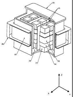
which
are yoked.
[00171] Compared to the known picture frame style "closed core" saturable
core fault current limiter, the above described embodiments have the following
advantages:
= A significant reduction in the mass of steel required and hence reduced
cost of
manufacture, transportation, and site location.
= For similar performance, a reduction in the footprint. This is
particularly
advantageous in easing placement issues at dense urban locations.
CA 02705347 2010-05-10
WO 2009/121143
PCT/AU2009/000409
31
=
= In those cases where a superconductor is employed for the DC bias coil or
coils, a lower cryostat surface area. This results in less steady state
ambient
heat loss, and hence a lower cryocooler power requirement.
= Mechanical de-coupling of the DC bias coil and cryostat from the AC phase
coils and steel core. This allows the oil tank to be lowered into the DC coil
warm bore area, or the DC coils may be lowered over the oil tanks containing
the phase coils and cores.
[00172] Compared to the alternative fault current limiter arrangements
such as
resistive types, resistive types with external or internal reactor, shielded
core, solid
state, the saturable open core fault current limiter has these advantages:
= The open core fault current limiter will not do harm to a protected line
and does
not need to be isolated from a protected line if any aspect of the
superconducting
portion fails, whether this be the DC coil, vacuum system, or cryogenic
system.
Hence, the open core fault current limiters of the embodiments are inherently
fail
safe and are able to be left in the protected line under these conditions.
Moreover,
the redundancy associated with alarms and detection of internal faults is able
to be
much less stringent compared to designs which must be switched out of service
for
an internal fault.
= None of the DC bias coils (whether it be a superconducting coil or
otherwise) is
directly connected to the high voltage or high current line of the grid or
electricity
supply that is being protected. Hence, simple, established and well known
dielectric design procedures are able to be used to design the high voltage
portion.
= Liquid cryogens are not used as an AC dielectric and, hence, issues
associated
with these liquids do not exist in the design of the preferred embodiments.
= Superconducting elements are not stressed by the fault current.
Accordingly,
there is very little induction of current and voltage into the DC coil during
a fault.
= The superconductor does not quench during a fault and hence is able to be
used
in-line where auto re-closers or re-closing logic is employed on the breakers
and
isolators of a protected line.
[00173] Reference throughout this specification to "one embodiment" or "an
embodiment" means that a particular feature, structure or characteristic
described in
connection with the embodiment is included in at least one embodiment of the
present
invention. Thus, appearances of the phrases "in one embodiment" or "in an
CA 02705347 2012-07-20
32
embodiment" in various places throughout this specification are not
necessarily all
referring to the same embodiment, but may. Furthermore, the particular
features,
structures or characteristics may be combined in any suitable manner, as would
be
apparent to one of ordinary skill in the art from this disclosure, in one or
more
embodiments.
[00174] Similarly it should be appreciated that in the above description
of
exemplary embodiments of the invention, various features of the invention are
sometimes
grouped together in a single embodiment, Figure, or description thereof for
the purpose of
streamlining the disclosure and aiding in the understanding of one or more of
the various
inventive aspects.
[00175] Further embodiments of the invention are disclosed in Australian
Patent
Application No. 2009901138 filed on 16 March 2009 and from which priority is
claimed.
[00176] Furthermore, while some embodiments described herein include some
but
not other features included in other embodiments, combinations of features of
different
embodiments ¨ including those embodiments disclosed in the patent
specifications from
which priority benefit is claimed ¨ are meant to be within the scope of the
invention, and
form different embodiments, as would be understood by those skilled in the
art. For
example, in the following claims, any of the claimed embodiments can be used
in any
combination.
[00177] In the description provided herein, numerous specific details are
set forth.
However, it is understood that embodiments of the invention may be practiced
without
these specific details. In other instances, well-known methods, structures and
techniques
have not been shown in detail in order not to obscure an understanding of this
description.
[00178] Those skilled in the art will recognize that these are examples
applied to
specific designs that were manufactured and that detailed results for other
designs with
different construction details will differ. The main conclusions and pattern
of results are
to be considered.
[00179] The scope of the claims should not be limited by the preferred
embodiments set forth in the examples, but should be given the broadest
interpretation
consistent with the description as a whole.