Note: Descriptions are shown in the official language in which they were submitted.
CA 02705633 2010-05-27
DESCRIPTION
Title Of The Invention
DISPLAY UNIT
Technical Field
This invention relates to a display unit in which images
taken by a camera or photographs or video images based on external
data are displayed before the eyes of a person by a display device.
Background Art
Conventionally, a technique has been developed for
displaying images taken by, for example, a camera or a sequence
of photographs, such as a motion picture, based on external data
in real time directly in the neighborhood of eyeballs of a user
or directly on a retina thereof.
For example, Japanese Published Unexamined Patent
Application No. 2006-85011 or Japanese Published Unexamined
Patent Application No . 2006-98827 can be mentioned as an example
of a display device that adopts holography. Additionally, a
retina scanning display device that displays images directly
on a retina of a user can also be used as another transmissive
display device.
As an example in which these display devices are adapted,
it is conceivable to use these devices for low-vision or
visually-impaired persons. In detail, the scenery around
(especially, in front of) a visually-impaired person who is a
user is imaged by a camera, and is displayed before the eyes
of the user by a display device so as to be used as visual assistance.
Generally, in a low-vision or visually-impaired person who has
residual vision, it is bad to give great light energy to the
CA 02705633 2010-05-27
retina of the person, and therefore external light is prevented
from entering the eyes of the person by wearing lenses having
a light blocking effect (hereinafter, referred to as "sunglass
lenses") .
For example, the structure of FIG. 9 or that of FIG. 10
is conceived as a display unit for visual assistance in which
sunglass lenses are used together.
FIG. 9 is a view showing an example of a display unit using
a transmissive display device that adopts holography. A sunglass
lens 101 is disposed on the outermost side (i.e . , on the object
side) of this display unit, and a transmissive display device
102 is disposed inside the sunglass lens 101. A corrective lens
105 is disposed inside the transmissive display device 102 (i.e.,
disposed closer to the eyeball) . The transmissive display device
102 includes a transparent board and an image projecting part
109 disposed on the upper part of the board. In the transmissive
display device 102, both a real image that has passed through
the transparent board 103 and a virtual image of a hologram can
be viewed in an overlapped state, and therefore this device is
called "transmissive."
FIG. 10 is a view showing an example of a display unit using
a non-transmissive display device. A sunglass lens 106 is
disposed on the outermost side of this display unit, and a monitor
107 of a non-transmissive display device is disposed inside the
sunglass lens 106. Unlike the transmissive display device, the
non-transmissive display device allows a real image to be viewed
only around the monitor 107.
2
CA 02705633 2010-05-27
However, in the display unit of FIG. 9, three lenses are
overlapped together in the front-back direction, thus leading
to a complex structure and an inferior outward appearance.
Therefore, it is preferable to unite the sunglass lens 101 and
the lens 105 together and dispose the lens 108 having a sunglass
function on the eyeball side of the transmissive display device
102 in the same way as in the display unit of FIG. 11.
Generally, the non-transmissive display device of the
display unit of FIG. 10 has a function to allow the device itself
to adjust visibility, and therefore another lens is not required.
However, if the monitor 107 is thick, problems will be caused
in the fact that its thickness makes it difficult to intercept
external light and in the fact that the lenses-wearing person
has an uncomfortable feeling because the sunglass lens 106 used
as a component is kept greatly away from the eyes forwardly.
Therefore, it is preferable to dispose the sunglass lens 106
closer to the eyeball than the monitor 107 as shown in FIG. 12.
However, there are many cases in which the characteristic
of blocking light on the short wavelength side having great energy,
more specifically, the characteristic of blocking light on the
ultraviolet side from near blue is normally given to the sunglass
lenses 101 and 106 as shown in a transmission characteristic
graph of FIG. 13. In other words, visible light that is external
light is viewed as yellowish light while allowing light excluding
blue light to remain. However, a color image is reproduced by
combining light's three primary colors R, G, and B together,
and therefore, if a structure in which the sunglass lenses are
disposed closer to the eyeball than the display device is adopted
3
CA 02705633 2010-05-27
as in FIG. 11 or FIG. 12, B light will likewise be almost cut
from light of images displayed on the display device as shown
in the graph of FIG. 13, and, as a result, the color image loses
blue, and becomes yellowish as a whole. On the other hand, in
the sunglass lenses, light on the blue side is originally cut,
and therefore there is no difference in color (i.e . , hue) after
all, and the scenery becomes yellowish as a whole before the
eyes of the user, and, as a result, the real image and the virtual
image must be distinguished from each other only by the difference
in brightness. Therefore, it becomes difficult to draw a
distinction between the real image and the virtual image.
On the other hand, in an example in which the sunglass lenses
101 and 106 are disposed on the more external side than the display
device (i.e., on the object side) as in FIG. 9 and FIG. 10, when
the scenery is viewed at nighttime, there is a case in which
it is difficult to draw a distinction between a virtual image
of a hologram and a real image that has passed through the sunglass
lenses 101 and 106 and that has been overlapped with the virtual
image, because the scenery is dark, and saturation is low.
The foregoing description is given as a noticeable problem
occurring in a visually-impaired person when the display unit
is structured such that the sunglass lenses are used in combination
with the display device. However, even if the person is not a
visually-impaired person, the same problem will arise in the
display unit in which the sunglass lenses are used in combination
with the display device.
Therefore, a technique capable of easily drawing a
distinction between a real image and a photographic image has
4
CA 02705633 2010-05-27
been required regardless of a positional relationship between
sunglass lenses and a display device.
The present invention has been made in consideration of
the problems existing in the conventional technique, and it is
an object of the present invention to provide a display unit
that enables a user to easily distinguish a real image and a
photographic image from each other regardless of a positional
relationship between sunglass lenses and a display device.
Disclosure of Invention
To solve the above-mentioned problems, a display unit
according to the present invention comprises an image data output
device, an image projecting device that visualizes image data
output from the image data output device and then projects the
image data so as to be perceived by eyes of a user, a skeleton
frame on which the image projecting device is mounted and that
is set so that a nasal dorsum of the user and auricle bases of
the user serve as parts that support the skeleton frame and
sunglass lenses that have a predetermined transmission
characteristic, the sunglass lenses being disposed directly or
indirectly on the skeleton frame and being disposed in front
of eyeballs of the user, respectively, in which the sunglass
lenses are set so that a transmissivity of visible light in a
predetermined wavelength region is peculiarly low and so that
transmissivities of visible light in wavelength regions other
than the visible light in the predetermined wavelength region
are peculiarly high, and in which the coloring of image light
visualized by the image projecting device is formed by light
5
CA 2705633 2017-03-10
differing in color from the visible light having peculiarly high
transmissivities in the sunglass lenses.
Additionally, a display unit according to the present
invention comprises an image pickup device, an image projecting
device that visualizes image data output from the image pickup
device and then projects a visualized image onto eyes of a user
so as to be perceived by the user, a skeleton frame on which
the image projecting device is mounted and that is set so that
a nasal dorsum of the user and auricle bases of the user serve
as parts that support the skeleton frame, and sunglass lenses
that have a predetermined transmission characteristic, the
sunglass lenses being disposed directly or indirectly on the
skeleton frame and being disposed in front of eyeballs of the
user, respectively; in which the sunglass lenses are set so that
a transmissivity of visible light in a predetermined wavelength
region is peculiarly low and so that transmissivities of visible
light in wavelength regions other than the visible light in the
predetermined wavelength region are peculiarly high, and in which
the coloring of image light visualized by the image projecting
device is formed by light differing in color from the visible
light having peculiarly high transmissivities in the sunglass
lenses.
Additionally, a display unit according to the present
invention comprising: an image data output device; an image
projecting device that visualizes image data output from the
image data output device and then projects the image data so
as to be perceived by eyes of a user; a skeleton frame on which
the image projecting device is mounted and that is set so that
6
CA 2705633 2017-03-10
a nasal dorsum of the user and auricle bases of the user serve
as parts that support the skeleton frame; and sunglass lenses
that have a predetermined transmission characteristic, the
sunglass lenses being disposed directly or indirectly on the
skeleton frame and being disposed in front of eyeballs of the
user, respectively; wherein the sunglass lenses are set so that
a transmissivity of visible light in a predetermined wavelength
region is low and so that transmissivities of visible light in
wavelength regions other than the visible light in the
predetermined wavelength region are high, wherein the coloring
of image light visualizedby the image projecting device is formed
by light differing in color from the visible light having high
transmissivities in the sunglass lenses, and wherein the image
projecting device is a transmissive display device that has an
image projection monitor displaying an image supplied from the
image data output device on a transparent board, and wherein
the sunglass lenses are disposed behind the transparent board
in a state of being overlapped with the transparent board.
Additionally, a display unit according to the present
invention comprising: an image data output device; an image
projecting device that visualizes image data output from the
image data output device and then projects the image data so
as to be perceived by eyes of a user; a skeleton frame on which
the image projecting device is mounted and that is set so that
a nasal dorsum of the user and auricle bases of the user serve
as parts that support the skeleton frame; and sunglass lenses
that have a predetermined transmission characteristic, the
sunglass lenses being disposed directly or indirectly on the
6a
CA 2705633 2017-03-10
skeleton frame and being disposed in front of eyeballs of the
user, respectively; wherein the sunglass lenses are set so that
a transmissivity of visible light in a predetermined wavelength
region is low and so that transmissivities of visible light in
wavelength regions other than the visible light in the
predetermined wavelength region are high, wherein the coloring
of image light visualized by the image projecting device is formed
by light differing in color from the visible light having high
transmissivities in the sunglass lenses, and wherein the image
projecting device is a non-transmissive display device that has
an image projection monitor displaying an image supplied from
the image data output device, and wherein the sunglass lenses
are disposed behind the image projection monitor in a state of
being overlapped with the image projection monitor.
Additionally, a display unit according to the present
invention comprising : an image pickup device; an image proj ecting
device that visualizes image data output from the image pickup
device and then projects a visualized image onto eyes of a user
so as to be perceived by the user; a skeleton frame on which
the image projecting device is mounted and that is set so that
a nasal dorsum of the user and auricle bases of the user serve
as parts that support the skeleton frame; and sunglass lenses
that have a predetermined transmission characteristic, the
sunglass lenses being disposed directly or indirectly on the
skeleton frame and being disposed in front of eyeballs of the
user, respectively; wherein the sunglass lenses are set so that
a transmissivity of visible light in a predetermined wavelength
region is low and so that transmissivities of visible light in
6b
CA 2705633 2017-03-10
wavelength regions other than the visible light in the
predetermined wavelength region are high, wherein the coloring
of image light visualizedby the image proj ecting device is formed
by light differing in color from the visible light having high
transmissivities in the sunglass lenses, and wherein the image
projecting device is a transmissive display device that has an
image projection monitor displaying an image supplied from the
image data output device on a transparent board, and wherein
the sunglass lenses are disposed behind the transparent board
in a state of being overlapped with the transparent board.
Additionally, a display unit according to the present
invention comprising : an image pickup device; an image projecting
device that visualizes image data output from the image pickup
device and then projects a visualized image onto eyes of a user
so as to be perceived by the user; a skeleton frame on which
the image projecting device is mounted and that is set so that
a nasal dorsum of the user and auricle bases of the user serve
as parts that support the skeleton frame; and sunglass lenses
that have a predetermined transmission characteristic, the
sunglass lenses being disposed directly or indirectly on the
skeleton frame and being disposed in front of eyeballs of the
user, respectively; wherein the sunglass lenses are set so that
a transmissivity of visible light in a predetermined wavelength
region is low and so that transmissivities of visible light in
wavelength regions other than the visible light in the
predetermined wavelength region are high, wherein the coloring
of image light visualizedby the image proj ecting device is formed
by light differing in color from the visible light having high
6c
CA 2705633 2017-03-10
transmissivities in the sunglass lenses, and wherein the image
projecting device is a non-transmissive display device that has
an image projection monitor displaying an image supplied from
the image data output device, and wherein the sunglass lenses
are disposed behind the image projection monitor in a state of
being overlapped with the image projection monitor.
In the thus formed structure, the image projecting device
allows the eyes of a user to perceive an image visualized based
on image data output from the image data output device. At this
time, image light has a hue differing from that of a real image
formed by external light that passes through the sunglass lenses
and then reaches the eyeballs of the user, in other words, the
6c1
CA 02705633 2010-05-27
color of image light and the color of a real image are different
from each other, and therefore a clear distinction can be drawn
between a photographic image and a real image, and the user can
recognize the visualized image as an image differing from the
real image without confusing the two images. For example, if
only blue of visible light is cut in a lens (i .e. , a sunglass
lens) , external light that passes through the lens will become
yellow by light in remaining wavelength regions. In this case,
colors other than yellow can be used as the color of photographic
image light.
The definition "the sunglass lenses are set so that a
transmissivity of visible light in a predetermined wavelength
region is peculiarly low" is not necessarily limited to the fact
that 100% of the visible light in the predetermined wavelength
region is cut. In other words, what is required is the fact that
visible light in a predetermined wavelength region to be intended
to be roughly cut is satisfactorily controlled by a sunglass
function. Additionally, it is permissible to peculiarly set the
transmissivity to be low in regions including an ultraviolet
region and a near-infrared region other than visible light.
Additionally, either the reflecting action of light or the
absorbing action of light (or, alternatively, both thereof) may
be used when light passing through the lens is cut. The term
"visible light in a predetermined wavelength region" denotes
visible light having a predetermined continuous width. The
definition "the sunglass lenses are set so that transmissivities
of visible light in wavelength regions other than the visible
light in the predetermined wavelength region are peculiarly high"
7
CA 02705633 2010-05-27
=
specifies a relative transmissivity with respect to the fact
that a transmissivity of visible light in a predetermined
wavelength region is peculiarly low, and does not necessarily
specify a 100% transmissivity.
In order to give a predetermined transmission
characteristic to a sunglass lens, it is generally performed
to use, for example, colored glass that contains pigments showing
an absorptive characteristic and a transmissive characteristic
with respect to a predetermined wavelength region. However, for
example, an interference filter may also be used to reflect light
having a specific wavelength . The interference filter is a filter
that selects only light having a specific wavelength from an
optical spectrum, and is a multilayer structure formed by piling
arbitrary dielectric thin films or arbitrary metallic thin films
in an arbitrary order so as to give a desired transmission
characteristic thereto. Additionally, the sunglass lens may be
used also as a lens. This lens is not necessarily required to
be designed so that a correction degree is set for near-sightedness
or astigmatism.
Examples of the image projecting device include a
transmissive display device that has an image projection monitor
displaying an image supplied from the image data output device,
more specifically, a transmissive display device that has a
transparent board that visualizes data based on, for example,
image data output from the image data output device and then
guides the resulting image light to a reflection light element
and a non-transmissive display device that has an image projection
monitor displaying an image supplied from the image data output
8
CA 02705633 2010-05-27
device. The term "reflection light element" mentioned here
denotes, in the transparent board, an element that has a surface
intersecting with a line extending in a direction in which the
eyes of the user are looking, and an element that has a surface
through which external light passes and onto which image light
reflected and guided in the transparent board is projected.
Examples of the reflection light element include a hologram
element and a half mirror. Additionally, a retina scanning
display in which a retina of the user is directly two-dimensionally
scanned with coherent visible light, such as laser light, so
as to recognize the visible light as an image without using the
reflection light element can be used as a non-transmissive display
device.
In the transmissive display device provided with the
transparent board, the sunglass lens may be disposed before the
transparent board (i.e., on the object side) or behind the
transparent board (i.e., on the eyeball side) . The reason is
that a photographic image (i.e., virtual image) and a real image
are mingled with each other even if any positional relationships
are formed between the sunglass lens and the transparent board,
and therefore the two images must be viewed with rays of light
having mutually different wavelengths. On the other hand, in
the non-transmissive display device provided with the image
projection monitor, the present invention is required to be
applied when the sunglass lens is disposed behind the monitor.
The image data output device may be an image pickup device.
In other words, as a generic concept, this denotes that a case
9
CA 02705633 2010-05-27
in which image data excluding the image data obtained by actually
performing photography is viewed is included.
Although a color image is composed of the three primary
colors RGB, the use of only one of these three colors makes it
possible to produce a hue that can be easily distinguished from
a real image. In particular, the maximum sensitive wavelength
of humans is about 560 nm in a bright scene, and is about 500
nm in a dark scene, and hence resides in a wavelength region
corresponding exactly to green. Therefore, images can be more
easily recognized by using green as an image color.
Preferably, the image light is obtained by projecting an
image taken by the image pickup device while using light of any
one of the three primary colors RGB.
Other aspects and advantages of the present invention will
become apparent from the following description, taken in
conjunction with the accompanying drawings, illustrating by way
of example the principles of the invention.
Brief Description of the Drawings
FIG. 1 is a perspective view of a display unit for visual
assistance according to an embodiment of the present invention.
FIG. 2 is a plan view of the display unit for visual assistance
same as FIG.1.
FIG. 3 is a block diagram for explaining an optical system
and an electric structure of a camera.
FIG. 4 is an explanatory view for explaining an optical
structure of an image projecting part.
CA 02705633 2010-05-27
FIG. 5 is a graph showing transmission characteristics of
a lens in a state of being overlapped with G light of a hologram
element.
FIG. 6 is an explanatory view schematically showing an
example of scenery viewed by a user.
FIG. 7 is a graph showing transmission characteristics of
the lens in a state of being overlapped with R light of the hologram
element in another example.
FIG. 8 is a schematic view of a display unit that uses a
non-transmissive display device in another example.
FIG. 9 is a schematic view of a transmissive display device
in which sunglass lenses are disposed on the outermost side.
FIG. 10 is a schematic view of a non-transmissive display
device in which sunglass lenses are disposed on the outermost
side.
FIG. 11 is a schematic view of a transmissive display device
in which sunglass lenses and a corrective lens are united together.
FIG. 12 is a schematic view of a non-transmissive display
device in which sunglass lenses are disposed on the innermost
side.
FIG. 13= is a graph showing a relationship between
transmission characteristics of sunglass lenses and image light
passing through a display device.
Detailed Description Of The Invention
A display unit according to an embodiment of the present
invention will be hereinafter described with reference to the
drawings.
11
CA 02705633 2010-05-27
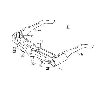
As shown in FIG. 1 and FIG. 2, the display unit for visual
assistance (hereinafter, referred to simply as "display unit")
11 is composed of a transmissive display device 13 mounted on
a skeleton frame 12 and corrective lenses 14. The skeleton frame
12 is composed of amain frame 15 and a pair of temples 17 connected
to both ends of the main frame by means of hinges 16, respectively.
A bracket 18 is attached to an inner surface of the center of
the main frame 15.
The transmissive display device 13 is composed of a camera
20 serving as an image pickup device, an image projecting part
21, and a transparent board 22 serving as an image projection
monitor. In this embodiment , the camera 2 0 is detachably attached
to a part near the left end of the main frame 15. Although the
image projecting part 21 is attached to the right upper end of
the transparent board 22 in this embodiment, the image proj ecting
part 21 may be attached to the left upper end of the transparent
board 22 or to the right and left upper ends of the transparent
board 22. The camera 20 and the image projecting part 21 are
connected together by means of a cable 23. A power source for
the camera 20 and the image projecting part 21 is not shown in
the figures in this embodiment.
As shown in FIG. 3, an optical system of the camera 20
according to this embodiment includes an RGB division optical
circuit 25 composed of a beam splitter and a prism, three
condensing lenses 26 disposed in accordance with each of the
RGB lights behind the RGB division optical circuit 25, and image
pickup tubes 27. The image pickup tubes 27 are connected to
amplifiers 28 and to a control circuit 29 respectively. A
12
CA 02705633 2010-05-27
photographic image is divided into three primary colors RGB in
the RGB division optical circuit 25, and the resulting colors
are guided to the image pickup tubes 27, and are converted into
signals, respectively. Each of the RGB images converted into
signals by the image pickup tubes 27 is processed by the amplifier
28 and the control circuit 2 9 , and is output to the image proj ecting
part 21 according to a predetermined signal system.
As shown in FIG. 4, the image projecting part 21 according
to this embodiment is composed of a light emitting diode (LED)
31 contained in a housing 30, a condensing lens 32, and a liquid
crystal display (LCD) 33. In this embodiment, the LED 31 is a
green light emitting diode that emits wholly green light.
Therefore, image data divided into three primary colors RGB is
projected in a green color. Image data output from the camera
20 through the cable 23 is projected from the LED 31 onto the
condensing lens 32 in the image projecting part 21, is then
modulated by the LCD 33, and is admitted into the transparent
board 22 through a corrective prism 22a disposed on the upper
part of the transparent board 22 in the form of an image beam
of light. The transparent board 22 totally reflects the image
beam of light while serving as a total reflection prism. The
image beam of light is guided to the hologram element 34 disposed
in the transparent board 22 while being reflected therein, is
then diffracted, and is admitted into the pupil. As a result,
a user can view a virtual image of a scene displayed on the LCD
33.
FIG. 5 is a graph showing transmission characteristics of
the lens 14 according to this embodiment in a state of being
13
CA 02705633 2010-05-27
overlapped with G light of the hologram element 34. In this
embodiment, light in a wavelength region below 450 rim is cut,
and the lens 14 is used also as a sunglass lens. Therefore, the
lens 14 cuts blue-based light of visible light that is external
light, and therefore a real image viewed by passing through the
lens 14 has a yellowish hue (tone) .
On the other hand, as described above, a virtual image by
means of G light is displayed on the hologram element 34 of the
transparent board 22. In the field of view of the user, a green
virtual image V is viewed in a state of being overlapped with
a yellowish real image RL passing through the lens 14 in a range
smaller than the range of the yellowish real image RL as shown
in, for example, FIG. 6.
This structure makes it possible to achieve the following
effects in this embodiment.
(1) If the corrective lens 14 that is used also as a sunglass
lens is disposed closer to the eyeball than the transparent board
22 of the transmissive display device 13, there has been a
possibility that a real image RL viewed through the lens 14 and
a virtual image V displayed on the hologram element 34 of the
transparent board 22 will have the systematically same hue because
of transmission characteristics of the sunglass lens.
However,
in this embodiment, a virtual image V to be displayed on the
hologram element 34 is displayed in green, and has a contrast
differing from that of a yellowish real image RL that is viewed
through the lens 14 and that is shown as a background, and therefore
a difference between the two images can be easily distinguished.
Especially, green belongs to a wavelength band easily perceived
14
CA 02705633 2010-05-27
by the eyes, and therefore a distinction therebetween can be
easily drawn.
(2) A virtual image V to be displayed on the hologram element
34 is displayed by projecting G light not by blocking R light
and B light from image data obtained by photography, and therefore
information given in the form of an image never deteriorates.
The present invention may be modified and embodied as
follows.
- As shown in FIG. 7, a virtual image V may be displayed
by R light not by G light. Additionally, a virtual image V may
be displayed by B light if transmission characteristics of the
lens 14 are changed. Additionally, of course, no problems occur
even if characteristics excluding those shown in FIG. 5 and FIG.
7 are adopted as transmission characteristics of the lens.
- In the above-mentioned embodiment, the transmissive
display device 13 that adopts holography is shown as an example.
However, the present invention can be, of course, applied to
a transmissive display device or a non-transmissive display
device that does not adopt holography. As shown in FIG. 8, a
non-transmissive display device used herein does not include
a transparent board 22 onto which a virtual image V is projected,
and an image is projected onto a monitor 36, unlike the
above-mentioned embodiment . In this example, it is recommended
to dispose a sunglass lens 37 closer to the eyeball than the
monitor 36. The reason is that, if the monitor 36 is closer to
the eyeball than the sunglass lens 37, a distinction between
a virtual image V and a real image can be fully recognized without
CA 02705633 2010-05-27
displaying the virtual image V and the real image in mutually
different contrasts as in the present invention.
- In the above-mentioned embodiment, an image is projected
by G light neither by R light nor by B light. However, R light
and B light may be cut, or G light and B light may be cut.
Additionally, R light and B light may be used so that the peak
of each wavelength of these lights is modulated into G light
in the control circuit 29.
- The structure of the image proj ecting part 21 is one example ,
and may be formed to have another optical system differing from
the above-mentioned one. Likewise, the structure of the camera
is one example, and may be formed to display a virtual image
only by G light by using another means differing from the
above-mentioned one.
15 - The camera 20 is used as an example of a device for sending
image data to the transmissive display device 13. However, the
transmissive display device 13 may be connected to a computer,
or to a DVD apparatus, or to a portable terminal device by wire
or by wireless so as to output an image thereto.
20 - The camera 20 is attached to the skeleton frame 12 . However,
this camera 20 may be set at a place except the skeleton frame
12. For example, it is conceivable to attach the camera 20 to
the upper part of the transparent board 22.
- The description specialized in the display unit 11 for
visual assistance is given as above. However, without being
limited to this, the invention can be embodied not for visual
assistance, as follows.
16
CA 02705633 2010-05-27
For example, let it be supposed that work in a factory,
such as stock control management in a warehouse, is performed.
A worker can simultaneously perform stock control management
while confirming information sent from a computer as a virtual
image output from a transmissive display device. For example,
information about a stock status in stock control management
or information about an assembly manual in product assemblage
can be conceived as information sent from the computer.
A case in which an operation, such as a surgical operation,
is performed while confirming a manual or a simulation screen
can be conceived when an inexperienced or knowledge-poor operator
performs the operation.
It is conceivable to assist a hearing-impaired person by
using software that converts sound information into character
information. The use of the present invention brings about a
great advantage because the sight of the hearing-impaired person
cannot be obstructed.
- Without being limited to the above-mentioned examples,
the present invention can be freely carried out in an aspect
not departing from the scope of the present invention.
-The present examples and embodiments are to be considered
as illustrative and not restrictive and the invention is not
to be limited to the details given herein, but may be modified
within the scope and equivalence of the appended claims.
17