Note: Descriptions are shown in the official language in which they were submitted.
CA 02705639 2010-05-10
WO 2009/068059 PCT/EP2007/010373
-1-
Tester for testing operational reliability of a cockpit oxygen distribution
circuit
The present invention relates to a tester for testing operational reliability
of a cockpit
oxygen distribution circuit having a plurality of components ensuring supply
of oxy-
gen from the cockpit oxygen distribution circuit to a cockpit crew of an
aircraft in an
emergency situation.
.0 Background art
The oxygen distribution circuit for the cockpit crew supplies oxygen to the
cockpit of
the aircraft in the event of the cabin pressure falling below a critical
value. In modern
aircrafts, the oxygen distribution circuit for the cockpit crew is separate
from the
.5 oxygen distribution circuit for the passengers of the aircraft. Typically,
the oxygen
distribution circuit for the passengers includes a chemical source of oxygen,
that is to
say, upon the cabin pressure falling below the critical value, a chemical
reaction is
initiated as a result of which oxygen is created. Conversely, the cockpit
oxygen dis-
tribution circuit uses oxygen bottles from which oxygen is supplied to the
cockpit of
PO the aircraft in an emergency situation.
Fig. 1 shows an example of a cockpit crew oxygen distribution circuit. An
oxygen
bottle 10 is provided as the oxygen source. The oxygen bottle 10 is connected
via
conduits 5, 15 to masks 4 for the cockpit crew. These masks 4 are normally
stored in
S storage boxes 3 from which they are released upon pressure drop inside the
cockpit.
A pressure gauge 20 is provided in the outlet of the oxygen bottle 10.
Reference
numeral 30 indicates a pressure regulator which regulates (reduces) the
pressure of
the gas provided by the oxygen bottle 10. An electromagnetic valve 40 is
provided in
order to start or terminate oxygen flow from the oxygen bottle 10. During
normal
operation of the aircraft, the electromagnetic valve 40 is normally open and
can be
closed by the cockpit crew via a switch provided inside the cockpit of the
aircraft (see
e.g. switch 44 in Fig. 4). Furthermore, a pressure switch 50 is provided in
conduit 15.
When the gas pressure inside conduit 15 drops below a predetermined value, the
pressure switch 50 opens, thereby initiating a low pressure signal on a
display inside
the cockpit for alerting the cockpit crew that the gas pressure inside conduit
15 is no
longer sufficient for providing the cockpit crew, in an emergency situation,
with a
sufficient amount of oxygen. It goes without saying that in an actual
aircraft, a plu-
CA 02705639 2010-05-10
WO 2009/068059 PCT/EP2007/010373
-2-
rality of these oxygen bottles 10 are provided and that conduit 15 branches
off to-
wards these oxygen bottles 10. Conduit 13 is provided for discharging an
overpres-
sure overboard the aircraft.
The ground tests of an aircraft require a number of different tests to be
conducted.
These tests include testing, for example, the pressure gauge 20, the pressure
regula-
tor 30, the electromagnetic valve 40 and the pressure switch 50 with regard to
cor-
rect connection of these components to the cockpit oxygen distribution
circuit, that is
to say whether these components are correctly connected to the signal lines
leading
to to control means inside the cockpit. Moreover, it is important to check
whether these
components can be controlled as specified, and that, for example, the correct
pres-
sure that can be provided by the cockpit oxygen distribution circuit to the
cockpit of
the aircraft is displayed correctly on a display inside the cockpit.
L5 It is therefore an object of the invention to provide a tester for testing
operational
reliability of a cockpit oxygen distribution circuit with which the electrical
connection
and the control of the various components of the cockpit oxygen distribution
circuit
can be tested for operational reliability.
o Summary
This and other objects are solved by a tester for testing operational
reliability of a
cockpit oxygen distribution circuit having a plurality of components ensuring
supply
of oxygen from the cockpit oxygen distribution circuit to a cockpit crew of an
aircraft
in an emergency situation. The tester according to the invention comprises
means for
electrically connecting the tester, in place of at least one of the
components, to the
oxygen distribution circuit, an indicator for indicating that the electrical
connection of
the tester to the cockpit oxygen distribution circuit has been established in
a prede-
fined manner, and switching means for initiating an output signal of the
tester,
wherein the output signal is indicative of an operation condition of the
component
when being connected to the cockpit oxygen distribution circuit.
The tester according to the invention is connected, in place of at least one
of the
components, to the cockpit oxygen distribution circuit. When connected, the
tester
indicates in a first step whether the tester is correctly connected. This
indication is
important because it indicates whether the components, after completion of the
tests, can be correctly wired to the electronic control infrastructure of the
cockpit
CA 02705639 2010-05-10
WO 2009/068059 PCT/EP2007/010373
-3-
oxygen distribution circuit. In a second step, switching means of the tester
are initi-
ated to simulate an output signal of the components (signals which would be
output-
ted if the components were connected to the cockpit oxygen distribution
circuit). This
output signal of the tester is transported to a corresponding display inside
the cockpit
for ascertaining that the operating condition of the hypothetically connected
compo-
nents meets specified requirements. The tester according to the invention
therefore
provides a simple tool for simulating the electrical connections of the
components of
the cockpit oxygen distribution circuit and the correct functioning of these
compo-
nents.
to
In a preferred embodiment, the output signal is indicative of a predefined
operating
condition of the component. Because the tester can generate through the use of
the
switching means an output signal which is indicative of a predefined operating
condi-
tion of the component that is simulated by the tester, particular emergency
condi-
.5 tions can be simulated by the tester and the behavior of the individual
components
can be checked in such situations. The operational reliability of the
components of
the cockpit oxygen distribution circuit can therefore be uniquely determined
on the
basis of the output signals of the tester. The operational reliability can be
verified by,
for example, displaying the simulated oxygen bottle pressure on a display
inside the
o cockpit and comparing this simulated oxygen bottle pressure with the actual
pressure
inside the oxygen bottle.
Preferably, the output signal of the tester corresponds to an output signal
generated
by the component when the component, now in place of the tester, is connected
to
the cockpit oxygen distribution circuit. Hence, the output signals are a
direct and
unambiguous measure of the actual operational characteristics of the
components
when the components are connected with the cockpit oxygen distribution
circuit.
According to another embodiment, the means for electrically connecting the
tester to
the cockpit oxygen distribution circuit comprises a plurality of terminals
each having
an input and an output. Preferably, the plurality of terminals correspond to a
plurality
of terminals provided on corresponding components of the cockpit oxygen
distribu-
tion circuit. In this way, the tester can easily be connected to the cockpit
oxygen
distribution circuit because of the terminals being provided on the tester are
identical
to the terminals being provided on the components, and therefore the use of
adap-
tors is avoided. This greatly facilitates the use of the tester for conducting
the opera-
tional reliability tests on the cockpit oxygen distribution circuit.
CA 02705639 2010-05-10
WO 2009/068059 PCT/EP2007/010373
-4-
Preferably, the switching means of the tester comprises a plurality of relays.
Fur-
thermore, the relays, upon switching, preferably allocate output signals to
outputs of
different terminals. Hence, the number of relays required is reduced due to
one relay
s accounting for simulating output signals which are indicative of operating
conditions
of several components of the cockpit oxygen distribution circuit.
In addition, the relays are preferably controllable by input signals received
by the
tester from control units located in the cockpit of the aircraft. It can
easily be tested
LO by actuating, for example, the electromagnetic valve via a corresponding
switch
provided inside the cockpit and, by using the tester, to simulate the pressure
now
acting upon the pressure regulator. This simulated pressure ought to initiate
a corre-
sponding pressure signal resulting in a particular pressure reading on a
pressure
gauge inside the cockpit. This pressure reading can be compared with
comparative
.s data in order to verify that the pressure reading is correct. If correct,
the electrical
control of the electromagnetic valve and the pressure regulator can be assumed
to
be as specified.
In another preferred embodiment, the indicator comprises a plurality of light
emitting
o diodes. These light emitting diodes allow the user of the tester to
immediately realize
whether the electrical connection of the tester, and thus of a component, to
the
cockpit oxygen distribution circuit is not as specified. Preferably, each
light emitting
diode is connected to an input of the plurality of terminals. Another
preferred em-
bodiment provides that each light emitting diode is active upon applying a
ground
potential to the input of the terminals.
In yet another embodiment, the tester is connected to the cockpit oxygen
distribu-
tion circuit, in place of a pressure regulator, an electromagnetic valve, an
oxygen
pressure gauge and a pressure switch. Thus, the electrical connection and
control of
the pressure regulator, the electromagnetic valve, the oxygen pressure gauge
and
the pressure switch can be tested with one single tester, all of which are
essential
components of a cockpit oxygen distribution circuit.
Preferably, the input and output signals of the tester are in the range of 0
Volts and
20 Volts DC.
CA 02705639 2010-05-10
WO 2009/068059 PCT/EP2007/010373
-5 -
Another aspect of the invention features the use of a tester for testing
operational
reliability of a cockpit oxygen distribution circuit having a plurality of
components
ensuring supply of oxygen from the cockpit oxygen distribution circuit to a
cockpit
crew of an aircraft in an emergency situation, wherein the tester is such as
previ-
ously described.
A yet another aspect of the invention features a method for testing
operational reli-
ability of a cockpit oxygen distribution circuit having a plurality of
components ensur-
ing supply of oxygen from the cockpit oxygen distribution circuit to a cockpit
crew of
to an aircraft in an emergency situation. The method according to the
invention com-
prises the steps of electrically connecting the tester, in place of at least
one of the
components, to the cockpit oxygen distribution circuit, verifying by means of
an indi-
cator that the electrical connection of the tester to the cockpit oxygen
distribution
circuit has been established in a predefined manner, and initiating switching
means
s for initiating an output signal of the tester, wherein the output signal is
indicative of
an operating condition of the component when being connected to the cockpit
oxy-
gen distribution circuit.
A preferred embodiment of the method according to the invention further
comprises
o the step of verifying that the output signal is indicative of a predefined
operating
condition of the component when being connected to the cockpit oxygen
distribution
circuit, and if not, adjusting the cockpit oxygen distribution circuit until
the output
signal is indicative of the predefined operating condition of the component.
5 Other features and advantages of the invention will become apparent from the
fol-
lowing detailed description of a preferred embodiment of the invention,
thereby
referring to the appended drawings.
Brief description of the drawings
0
Fig. 1 is a schematic representation of an example of a cockpit oxygen
distribution
circuit installed onboard of an aircraft;
Fig. 2 is a wiring diagram of a tester according to the invention, showing
terminals of
5 the tester to be connected with terminals of the cockpit oxygen distribution
circuit;
CA 02705639 2010-05-10
WO 2009/068059 PCT/EP2007/010373
-6-
Fig. 3 is a wiring diagram of an electronic board provided inside the tester
according
to the invention; and
Fig. 4 shows, by way of example, control of an electromagnetic valve via a
switch
provided inside the cockpit of an aircraft.
Detailed description of a preferred embodiment
As already described with reference to Fig. 1, a cockpit oxygen distribution
circuit
requires frequent maintenance tests, thereby inspecting whether the individual
com-
ponents of the cockpit oxygen distribution circuit can be correctly connected
to the
electronic control infrastructure of the cockpit oxygen distribution circuit
installed
onboard of the aircraft. Once it has been established that the electrical
connection of
the components is as specified, it has to be verified, in addition, that
control of the
individual components via signal lines to and from these components to
actuators,
switches, displays etc. installed, for example, inside the cockpit of the
aircraft is such
that, in an emergency situation, the cockpit crew is supplied with sufficient
oxygen
from the cockpit oxygen distribution circuit. The tester according to the
invention
provides an easy and convenient way of conducting these tests.
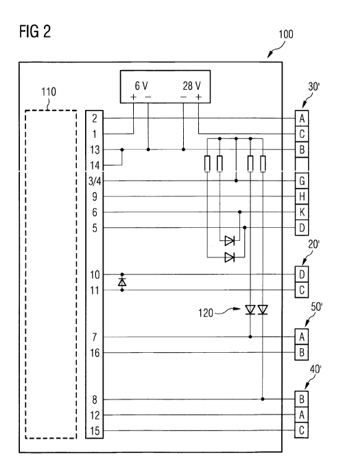
Fig. 2 is a wiring diagram of a tester 100 according to the invention. The
tester com-
prises terminals 20', 30', 40', 50' which are to be connected to terminals of
the elec-
tronic infrastructure of the cockpit oxygen distribution circuit 1 (see Fig.
1), in place
s of the components, such as the pressure gauge 20, pressure regulator 30,
electro-
magnetic valve 40 and pressure switch 50 (see Fig. 1). In particular, terminal
30' is
to be connected with a corresponding terminal of pressure regulator 30,
terminal 20'
is to be connected with a corresponding terminal of pressure gauge 20,
terminal 50'
is to be connected with a corresponding terminal of pressure switch 50 and
terminal
3 40' is to be connected with a corresponding terminal of an electromagnetic
valve 40.
Thus, during ground tests of the aircraft, the individual components 20, 30,
40, 50
are replaced by the tester 100.
Tester 100 accommodates an electronic board 110 which will be described in
detail
with reference to Fig. 3. Furthermore, four light emitting diodes (LEDs) are
provided
for indicating whether each terminal 20', 30', 40', 50' is correctly connected
to corre-
sponding terminals of the cockpit oxygen distribution circuit. LEDs 120 are
connected
CA 02705639 2010-05-10
WO 2009/068059 PCT/EP2007/010373
-7-
to respective signal lines of terminals 20', 30', 40', 50'. As can be seen in
Fig. 2, LEDs
120 will be active upon connecting signals lines of contacts K, D of terminal
30',
contact A of terminal 50' and contact B of terminal 40' to a ground potential.
If all of
the LEDs are active, the user of the tester 100 can be assured that the
connection of
the tester 100 to the respective terminals of the cockpit oxygen distribution
circuit 1
is established as required. If one, or all, of the LEDs remain inactive, the
connection
is not as specified from which the user can infer that connecting the original
compo-
nents, such as the pressure regulator 30, to the cockpit oxygen distribution
circuit
will result in malfunctioning of that component. Hence, by means of LEDs 120,
it can
.0 be ascertained that the wiring to and from the terminals of the cockpit
oxygen distri-
bution circuit is correct and that no signal lines are, for example,
interrupted, short or
faulty for some other reason.
With reference to Fig. 3, the electronic board indicated by reference numeral
110 in
5 Fig. 2 is shown in detail. In the following, the electronic board of Fig. 3
will be ex-
plained, by way of example, in terms of its functions and which tests can be
con-
ducted on the cockpit oxygen distribution circuit using the tester 100. Three
different tests will be described. It is pointed out that the tests given here
by way of
example are not exhaustive, and that other tests can be conducted using the
tester
100. For the sake of the description of the three tests, it is assumed that
upon con-
nection of the tester 100 to the cockpit oxygen distribution circuit 1, all of
the LEDs
120 of the tester 100 were active.
Upon connection of tester 100 with the cockpit oxygen distribution system, a
current
flow will be induced in transistor Ti as a consequence of which relay RL4 will
be
closed. Hence, a 2 V signal is applied to contact 2 which corresponds to
contact A of
terminal 30'. The 2 V output signal corresponds to a 2 Volt output signal
normally
generated by pressure regulator 30 during normal operation of the aircraft.
This 2 V
output signal effects a predefined oxygen pressure reading (x psi) being
displayed on
a display inside the cockpit of the aircraft. In other words, tester 100
simulates an
output signal of pressure regulator 30 in order to verify that this output
signal results
in a correct oxygen pressure reading on the display inside the cockpit of the
aircraft.
A second exemplary test includes activation of switch 44 provided in the
cockpit of
the aircraft and establishing an operative connection between power supply 42
and
switch 44 (see Fig. 4). Upon pressing switch 44, the voltage supplied by the
power
supply 42 (here 28 V) is applied to contact A of electromagnetic valve 40.
With refer-
CA 02705639 2010-05-10
WO 2009/068059 PCT/EP2007/010373
-B-
ence to Fig. 2, contact A of terminal 40' corresponds to contact 12 of the
electronic
board 110. Hence, a 28 V input signal on contact 12 (see Fig. 3) effects
closing relay
RL1, and hence a 4 V output signal is applied to contact 2 of the electronic
board
110. Contact 2 corresponds to contact A of terminal 30' (see Fig. 2). Thus, a
4 V
output signal is applied to contact of A of terminal 30'. The 4 V output
signal is nor-
mally generated by the pressure regulator 30 during normal operation of the
aircraft.
The 4 V output signal on contact A of terminal 30' will effect another oxygen
pres-
sure reading (y psi) being displayed on a display inside the cockpit of the
aircraft. If
the oxygen pressure reading is correct, it is ascertained that the electrical
wiring and
.0 control of the pressure regulator 30 is as specified. Furthermore, it can
be tested
whether the output signal generated during normal operation of the aircraft by
the
pressure regulator effects a correct oxygen pressure reading on the display
inside the
cockpit.
s As a third exemplary test, switch 44 is manually opened thereby maintaining
opera-
tive connection to power supply 42. In the open state of switch 44, the
voltage of the
power supply 42 (28 V) is applied to contact C of electromagnetic valve 40
(see Fig.
4). Contact C of electromagnetic valve 40 corresponds to contact 15 of
electronic
board 110 (see Fig. 2). A 28 V input signal on contact 15 results in closing
relay RL3,
o thus connecting contact 16 with the ground potential. Consequently, contact
B of
terminal 50' is at ground potential which effects a low oxygen pressure alarm
inside
the cockpit. If the third exemplary test results in an alarm inside the
cockpit, it is
ascertained that the electrical wiring up to contact C of terminal 40' (and
thus of
electromagnetic valve 40) is as specified. At the same time, it can be
verified that the
s pressure switch 50 outputs a correct output signal during normal operation
of the
aircraft by verifying whether a corresponding alarm signal is initiated inside
the cock-
pit of the aircraft.
The essence of the invention is to provide an easy and convenient way of
testing a
plurality of components of a cockpit oxygen distribution circuit installed
onboard of
an aircraft. Instead of testing the components themselves, the components are
with-
drawn from the cockpit oxygen distribution circuit, and terminals of a tester
accord-
ing to the invention are connected to the terminals of the cockpit oxygen
distribution
circuit to which the plurality of components are normally connected.
By having provided on the tester corresponding indicators, LEDs in the
preferred
embodiment, it can. easily be verified that the electrical wiring of the
electronic con-
CA 02705639 2010-05-10
WO 2009/068059 PCT/EP2007/010373
-9-
trol infrastructure of the cockpit oxygen distribution circuit up to the
terminals of the
components is as specified. Once the correct wiring scheme has been
established,
various tests can be conducted in order to simulate by the tester output
signals of
the various components in order to verify that these output signals effect,
for exam-
ple, corresponding oxygen pressure readings on a display inside the cockpit.
Hence,
the tester according to the invention greatly simplifies the ground tests of
an aircraft,
in particular with respect to tests of the operational reliability of the
cockpit oxygen
distribution circuit.
9032