Note: Descriptions are shown in the official language in which they were submitted.
CA 02705866 2010-05-13
WO 2009/065216 PCT/CA2008/002035
HEAT RECOVERY VENTILATOR WITH DEFROST
TECHNICAL FIELD
The present invention relates to a defrost system for a heat recovery
ventilator/energy recovery
ventilator (HRV/ERV), and in particular to a defrost system that utilizes
interior space supply air
to defrost the core in the integrated fan coil of the HRV/ERV.
BACKGROUND OF THE INVENTION
An integrated fan coil refers to an air handling system which combines in one
appliance the
typical functions of a hydronic or direct exchange air handler and the typical
functions of an
HRV/ERV device. A typical direct exchange air handler includes a forced air
furnace circulating
heated or air conditioned air to an interior space via a duct or direct grille
return system. A
typical HRV or ERV device brings fresh air into an interior space from
outdoors via a duct
system with a heat exchange core, and expels exhaust and stale air from that
same interior space
via the heat exchange core, which transfers sensible and latent energy from
the exhaust air to the
fresh air. Typically, the HRV/ERV core, helps control the relative humidity of
the interior
space, and recovers energy from the exhaust air stream.
Conventional HRV devices, such as those disclosed in United States Patents
Nos. 4,653,574
issued March 31, 1987 to L.B. White Company, Inc; 5,257,736 issued November 2,
1993 to
Donald Roy; 5,855,320 issued January 5, 1999 in the name of Nutech Energy
Systems Inc.; and
6,169,849 issued January 2, 2001 to Olsberg Hermann Everken GmbH, provide a
heat
exchanging core to enable the transfer of heat from exhaust air to intake air.
Unfortunately, prior
art HRV systems do not, without drawbacks, solve the problem of heat exchange
cores becoming
too cold and frosting over.
A simple conventional defrosting system is to shut down the fresh air input
fan and exhaust
interior air through the heat exchange core. Unfortunately, fan shut-down
defrost systems cause
negative pressurization of the interior space, as they exhaust air through the
HRV/ERV core to
thaw the core out, without introducing fresh air into the interior space
because the fresh air fan is
"shut down" during defrost cycles. Moreover, during defrost cycles, fan shut-
down HRV/ERV
systems expel heat from the interior space without passing any of that heat on
to incoming fresh
1
CA 02705866 2010-05-13
WO 2009/065216 PCT/CA2008/002035
air, since fresh air is not coming into the building when the fresh air fan is
shut off, resulting in
heat energy loss. Another short-coming of fan shut-down defrost systems is
that they take longer
to defrost the HRV/ERV core than other defrost systems because fan shut-down
systems provide
warm air to only one side of the core.
There is no negative pressurization of the interior space and its associated
heat energy loss, no
need to locate or run special ductwork, nor any special consideration needed
for unit location (in
terms of defrost performance), all typical disadvantages of "5th port" defrost
systems.
Conventional 5th port defrost systems address the issue of feeding defrost air
to both sides of the
HRV/ERV core, thereby performing their function faster than fan shut-down
defrost systems;
however, they still create negative pressurization of the interior space
resulting in energy losses.
Another disadvantage of 5th port defrost systems is that they require an extra
duct, which is used
for defrost purposes, to be run between the unit and the interior space. As
the space in building
design for mechanical ventilation systems is usually minimal, adding a 5th
port can present major
space and aesthetic issues, not to mention added costs of running the duct for
the 5th port .
Alternatively, the HRV/ERV could be located in a room to draw defrost air into
the unit directly.
While this method of installation eliminates the need for special ductwork,
care must be given in
unit location: the room in which the unit is located must be heated and this
room must not
contain any source of noxious odours or airborne chemicals.
Re-circulation defrost systems address the efficiency, space, aesthetic and
cost shortcomings of
fan shut-down and 5th port defrost systems; however, recirculation defrost
systems re-circulate
stale and exhaust air through the HRV/ERV core, thus delivering, stale and
perhaps smelly air to
the interior space during defrost cycles, adversely affecting the level of
comfort experienced by
occupants of the interior space.
An object of the present invention is to overcome the shortcomings of the
prior art by providing
a HRV or ERV defrosting unit, which doesn't require negative depressurization
of the interior
space, an external 5th port, or re-circulation of exhaust air into the
interior space.
2
CA 02705866 2010-05-13
WO 2009/065216 PCT/CA2008/002035
SUMMARY OF THE INVENTION
Accordingly, the present invention relates to an energy recovery ventilator
(HRV) located within
an interior space including a first set of rooms and a second set of rooms
comprising:
a fresh air inlet port for inputting fresh air from outside the interior
space;
an exhaust air inlet port for inputting exhaust air from the first set of
rooms;
a heat exchange core for transferring heat from the exhaust air to the fresh
air;
an exhaust air outlet port for outputting the exhaust air outside the interior
space;
a return air input port for inputting return air from the second set of rooms;
a first fan for drawing the return air in to form supply air, for drawing the
fresh air in forming a
mixture of the fresh air and the supply air , and for blowing the mixture of
the fresh air and the
supply air into the interior space;
a supply air outlet port for outputting the mixture of fresh air and supply
air to the interior space;
a second fan for drawing in the exhaust air through the ERV core, and for
blowing the exhaust
air out the exhaust air outlet port;
a first damper having a first open position enabling the fresh air to pass
through the fresh air inlet
port, and a second position preventing fresh air from passing through the
fresh air inlet port;
a second damper having a first open position enabling exhaust air to pass
through the exhaust air
inlet port, and a second position preventing exhaust air from passing through
the exhaust air inlet
port;
a third damper having a first open position enabling exhaust air to pass
through the exhaust air
outlet port, and a second position preventing exhaust air from passing through
the exhaust air
outlet port;
a damper control for controlling the position of the first, second and third
dampers,
3
CA 02705866 2010-05-13
WO 2009/065216 PCT/CA2008/002035
whereby when the first, second and third dampers are positioned in the closed
positions, supply
air, after passing through the first fan, is redirected by the first and
second dampers through the
ERV core, and by the third damper to the interior space.
BRIEF DESCRIPTION OF THE DRAWINGS
The invention will be described in greater detail with reference to the
accompanying drawings
which represent preferred embodiments thereof, wherein:
Figure 1 is an isometric view of the integrated fan coil of the present
invention
Figure 2a is a side view of an integrated fan coil of Fig 1;
Figure 2b is a front view of the integrated fan coil of Fig 1;
Figure 2c is a side view of the integrated fan coil of Fig 1;
Figure 2d is a top view of the integrated fan coil of Fig 1;
Figures 3a to 3c illustrates the flow of air through the integrated fan coil
of Fig 1 during normal
operation;
Figure 4 is a front view of the upper section of the integrated fan coil of
Fig 1 with the dampers
in the closed (normal) position;
Figure 5 is a front view of the upper section of the integrated fan coil of
Fig 1 with the dampers
in the open (defrost) position; and
Figures 6a to 6d illustrate the flow of air through the integrated fan coil of
Fig 1 during
defrosting operation.
DETAILED DESCRIPTION
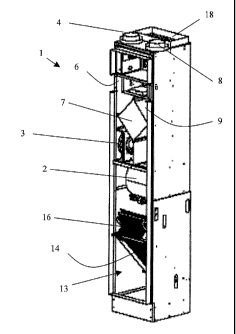
With reference to Figures 1 to 3c, the integrated fan coil of the present
invention includes a
generally rectangular housing 1 resting on one end, with a main fan 2 and a
secondary fan 3
disposed proximate the middle thereof. During normal operation, the main fan 2
draws in fresh
air from the outside, draws in return air only from a first group of selected
rooms on the inside of
4
CA 02705866 2010-05-13
WO 2009/065216 PCT/CA2008/002035
the structure, and delivers supply air to all of the rooms on the inside of
the structure. A
secondary fan 3 is provided for drawing in exhaust air only from a second
group of selected
interior rooms for preheating the fresh outside air, as explained hereinafter,
and delivering the
exhaust air to the outside of the structure. Although this description refers
to specific locations of
air ports, it should be noted that the location of these ports may vary as
building design dictates.
During normal operation, fresh outside air is drawn in by the main fan 2
through the fresh air
intake port 4, at an upper end of the housing 1, down along a fresh air intake
passage 6 in the
front left portion of the housing 1 to one side of an ERV core 7, e.g. a heat
exchanger, as in Fig
3b. Simultaneously, stale, humid exhaust air from the second group of selected
interior rooms,
e.g. bathrooms, kitchens, laundry and exercise rooms, different than the first
group or rooms, is
drawn in by the exhaust fan 3 through an exhaust air intake port 8, at the
upper end of the
housing 1, down along an exhaust air intake passage 9 in the front right side
of the housing 1 to
another side of the ERV core 7 for exchanging energy with the fresh intake
air, e.g. preheating
during winter or precooling during summer. After passing through the ERV core
7, the exhaust
air is delivered back up to an exhaust output port 11, extending out of the
side of the housing 1
near the upper end of thereof, via an exhaust air output passage 12 in the
back left side of the
housing 1, which is adjacent to the fresh air intake passage 6 to further
provide energy exchange
between the exhaust air and the incoming fresh air, as in Fig. 3a.
Return air, drawn in by the main fan 2 from the first group of selected
interior rooms, e.g. less
humid rooms such as bedrooms, living rooms, family rooms, and offices, enters
the housing 1
via the return air port 13, and then passes through an air filter 14 and a
heat treatment, e.g.
heating and/or cooling, device 16, one or both of which can be within the
housing 1 or in a
separate housing to become supply air as positive pressure is applied. The
illustrated fan coil
includes water coils for heating and/or cooling, but any combination of
heating devices and
cooling devices, including standard natural gas or oil burners and air
conditioners, is within the
scope of the invention. The heat treatment device 16 can be set to a
circulation mode, in which
no heat is transferred, but air is simply circulated throughout the building.
The heated or cooled
(treated) supply air is mixed by the main fan 2 with incoming fresh air
pretreated in the ERV
core 7, which is then delivered to the interior rooms of the building, e.g.
both the first and second
groups of interior rooms, via the supply air passage 17 and supply air outlet
port 18, at the upper
5
CA 02705866 2010-05-13
WO 2009/065216 PCT/CA2008/002035
end of the housing 1, adjacent the fresh and exhaust air intake ports 4 and 8,
respectively, as in
Fig. 3c. Suitable duct work is connected to the supply air outlet port 18 for
delivering the supply
air to the various rooms throughout the building.
With reference to Figure 4, a first damper 21 is pivotally mounted within the
fresh air intake
passage 6 enabling fresh air to pass therethrough when in a first position
during normal
operation, while preventing fresh air from entering the fresh air intake
passage 6 when in a
second position during defrosting operation. A link 22 connects the first
damper 21 to a rod 23,
which is rotated by a motor 24, for pivoting the first damper between the
first and second
positions.
A second damper 26 is pivotally mounted within the exhaust air intake passage
9 enabling the
exhaust air to pass therethrough when in a first position during normal
operation, while
preventing exhaust air from entering the exhaust air intake passage 9 when in
a second position
during defrosting operation. A link 27 connects the second damper 26 to the
rod 23, which is
rotated by the motor 24 for pivoting the second damper between the first and
second positions,
along with the first damper 21. A third damper 28 is pivotally mounted within
the exhaust air
output passage 12 enabling the exhaust air to pass through the exhaust air
output port 11 during
normal operation, while diverting air from the exhaust air output port 11 to
the supply air output
passage 17 during the defrosting operation. The third damper 28 can be
connected to the first
damper 21, so that rotation of the first damper 21 results in rotation of the
third damper 28.
A control center, typically mounted in or on the housing 1, but possibly
mounted remote from
the integrated fan coil, includes a micro-controller, with some form of
memory, electronically
connected to the main fan 2, the secondary fan 3, the heating/cooling device
16, a temperature
sensor 19, and the damper motor 24 for control thereof. The temperature sensor
19 is positioned
within the housing 1 proximate the ERV core 7 to provide an accurate measure
of the
temperature in the ERV core 7 During normal operation, the control center
takes input from a
thermostat and/or dehumidistat placed strategically within the building, and
cycles the
heating/cooling device 16 along with the main and secondary fans 2 and 3,
respectively, between
active and inactive to ensure the temperature and/or relative humidity of the
building remains at
the predetermined temperature set by the occupants of the building.
Alternatively, the integrated
6
CA 02705866 2010-05-13
WO 2009/065216 PCT/CA2008/002035
fan coil can be run in a simple ventilation mode with the main and secondary
fans 2 and 3,
respectively, running, but without any temperature adjustment by the
heating/cooling device 16.
When the temperature sensor 19 detects the temperature in the incoming fresh
air before, after or
during preheating, but preferably before, to be below a predetermined
threshold value, e.g. -5 C
to +5 C, but preferably 0 C, the control center switches the integrated fan
coil to the defrost
mode by first switching on the motor 24 and rotating the first, second and
third dampers 21, 26
and 28 to their second (closed) positions. Accordingly, fresh air is prevented
from entering the
ERV core 7 and from being delivered to the interior rooms of the building.
Moreover, stale
exhaust air is also prevented from entering into the ERV core 7, and from
being exhausted to the
outside via exhaust output port 11. Furthermore, as illustrated in Figures 5
and 6a to 6d, a
portion of the supply air, made up of return air only, is diverted by the
first damper 21 from the
supply air passage 17 back through the fresh air intake passage 6, and through
one side of the
ERV core 7 to the main fan 2, see A in Fig. 5. Simultaneously, another portion
of the supply air
is diverted by the second damper 26 from the supply air passage 17 back
through the exhaust air
intake passage 9, and through the other side of the ERV core 7 to the
secondary fan 3, see B in
Fig. 5. The warm, dry supply air, diverted from the supply air passage 17,
defrosts the ERV core
7 from both sides to ensure even warmth and efficient heat transfer. The main
fan 2, recirculates
the defrost air from the air intake passage 9 back up the supply air passage
17 for output to the
building via supply air output port 18 or diversion back through the ERV core
7 again, see D in
Fig. 5. The secondary fan 3 recirculates the defrost air back up through the
exhaust air output
passage 12 to the third damper 28, which diverts the defrost air into the
supply air passage 17
and out the supply air output port 18 to the rooms in the building, see C in
Fig. 5.
The supply air is pushed (positive pressure) into the supply air passage 17 by
the main fan 2.
After passing through the ERV core 7, the main fan 2 draws (negative pressure)
the air back into
the main fan 2. Some of the air finds its way back into the defrost circuit
and some of it passes
out of the fan coil through the supply air passage 17.
The supply air is pushed by the main fan 2 through the exhaust side of the HRV
core 7. After
passing through the core 7 the secondary fan 3 takes over and draws that air
up the exhaust air
7
CA 02705866 2010-05-13
WO 2009/065216 PCT/CA2008/002035
outlet passage 12 and pushes it into the supply air passage 17, some of which
will enter the
building space, some of which will follow the defrost circuit again.
During the defrost mode, both the main and secondary fans 2 and 3 are run at a
lower speed than
during normal operation, unless other parameters dictate otherwise. The
defrost mode continues
for a predetermined time period, e.g. 1 to 5 minutes, then the integrated fan
coil returns to normal
operation for another predetermined time period (e.g. 30 minutes) If during
the second time
period the temperature sensor 19 detects a temperature below the threshold
temperature, the
defrost cycle is repeated. If the temperature of the incoming fresh air
remains above the
threshold temperature, then the integrated fan coil continues in normal
operation.
The ERV core defrosting system of the present invention is practical for
integrated fan coils
used in multi-unit housing or lodging, e.g. apartments, hotels and
condominiums, and small
single-family homes. The integrated fan coils can be the indoor component of
known direct
exchange (Dx) split systems or the en suite component of known two- or four-
pipe hydronic air
treatment systems, which use a central heating and/or cooling plant.
The present invention prevents the ERV/HRV core 7 of the integrated fan coil
from freezing
during cold weather operation. Advantageously, the present invention maintains
neutral
pressurization of the interior space during the defrost operation by blocking
both the fresh air
intake port 3 and the exhaust air output port 11 in the defrost mode. Blocking
the exhaust air
output port 11 also saves energy by eliminating the need to exhaust air from
the interior space for
the purpose of defrosting the HRV/ERV core. Another feature of the present
invention is that
particularly stale, e.g. humid or odorous, interior air is not used for the
purposes of the
HRV/ERV defrost by having separate intake ports for different sets of rooms,
i.e. one set with
particularly stale air and one set with normal air. To defrost mode is
shortened as much as
possible by delivering warm interior space air to both sides of the HRV/ERV
core 7 at the same
time.
8