Note: Descriptions are shown in the official language in which they were submitted.
= CA 02705892 2015-08-07
1
AQUACULTURE NET WITH STEEL WIRES COATED WITH METAL STRIP
Description
Technical Field
[0001] The invention relates to an aquaculture net with steel wires.
Background Art
[0002] Aquaculture nets or fish-farming nets are used to raise aquatic life
such as fish.
The aquaculture net keeps the aquatic life controlled and contained and
protects
the aquatic life inside the net against predators such as sharks and sea
wolfs.
[0003] The aquaculture nets are usually of the chain-link fence type. This is
a fence of
steel wires woven into a diamond pattern. The meshes have a dimension that is
smaller than the dimension of the fish contained in the nets. Each steel wire
is
preformed by bending so that it exhibits a wavy pattern with maxima and
minima.
The maxima of a steel wire interlock with the minima of a neighbouring wire to
form the patterns of a series of diamonds.
[0004] Experience has shown, however, that aquaculture nets of the chain-link
fence
type also have some disadvantages. Aquaculture nets have been discovered
where one or more of the steel wires were broken after a limited life time.
[0005] Investigation of the failing aquaculture nets revealed that
particularly the upper
steel wires in the aquaculture net were broken. Indeed, the ocean or the sea
forms a huge challenge with respect to corrosion-resistance. In addition to
this
highly corroding environment, the waves and tidings subject the aquaculture
net
to a continuous and repeated movement. In an aquaculture net of the chain-link
fence type, each steel wire must carry the weight of the rest of the net below
it.
The upper wire makes point contacts with the wire just below it. These point
contacts are located at a point where both the upper wire and the wire just
below
it are subjected to both a bending and a torsion deformation. The continuous
and repeated
CA 02705892 2010-05-14
WO 2009/095135 PCT/EP2008/067553
2
imposed movements in this aggressive environment create fretting at the
point contacts and may result in breaking the wires of the net.
[0006] Aquaculture nets with galvanized steel wires offer an acceptable
resistance against bio-fouling, i.e. against fouling material that may grow
on the mesh structure. Within the context of the present invention, the
terms fouling material refer to fouling organisms such as barnacles, algae
or molluscs, which may attach and grow to the wire material of the mesh
structure. However, this fouling mechanism may be so persistent that
entire openings in the meshes may be filled blocking any introduction of
fresh water or nutrition into the volume inside the mesh structure.
[0007] Therefore, there is a need for aquaculture nets with better anti-
fouling and
anti-corrosion properties.
[0008] JP-A-2004-261023 discloses a steel wire for aquaculture nets. The steel
wire has a stainless steel core and a metal coating of cupronickel: a
copper nickel alloy with nickel content ranging between 10 % and 30 % by
weight. The metal coating can be applied either by hot dipping the
stainless steel core in a copper nickel bath or by plating the stainless steel
core with copper, thereafter with nickel and finally applying a thermal
diffusion treatment.
[0009] Copper nickel coatings have proven to provide a good resistance against
corrosion because of the nickel and have proven to provide a good
resistance against fouling because of the effect of copper. However, the
existing prior art steel wires with copper nickel coatings lack the
possibility
to fine tune the thickness and the composition of the copper nickel coating
because of following reasons or do not offer high quality steel wires with a
thick coating.
[0010] If a hot dip copper nickel bath is used, the composition of the copper
nickel
coating can be varied by varying the composition of the copper nickel
bath. The thickness, however, largely depends upon the wire speed of
leaving the bath and upon the final degree of rolling or drawing. It is
difficult, if not impossible, to obtain steel wires with a coating the
thickness
of which exceeds 30% of the wire diameter. Moreover, having regard to
the high melting temperature of both copper and nickel in comparison with
. CA 02705892 2015-08-07
3
zinc, it is difficult to manufacture high-quality coated wires due to
oxidation
problems at the surface of the steel core.
[0011] If a thermal diffusion treatment is applied, the thickness of the
copper nickel
coating can be predetermined by increasing the time for (electro)-plating. It
is
hereby understood that the longer the plating treatment the thicker the
coating
and vice versa, all other parameters being constant. The composition, however,
is more difficult to control. As the nickel is applied on top of the copper,
nickel
diffuses through the copper from the top and also from the stainless steel
core
since stainless steel also comprises nickel due to downstream heat treatments.
This diffusion process, however, is difficult to control and to fine tune. As
a
result, with a thermal diffusion treatment it is impossible to obtain a
coating with
e.g. 90 wt% copper and 10 wt% nickel and having this same composition
throughout the thickness of the coating.
[0012] The dimensions of an aquaculture net are considerable. An example of a
typical
dimension is 30m x 30m x 15m, the last dimension being the depth of the net
inside the water and the first two dimensions being the width and length of
the
net at the water surface. As a matter of example only, a net made of
galvanized
steel wire and of the above-mentioned dimensions has a weight above 4 metric
Tonnes. An embodiment of an aquaculture net has been disclosed in
WO-A1 -2007/031352. As such the weight of an aquaculture net needs to be
kept to a minimum. A tuneable coating guarantees thickness thus controllable
weight of the wires and the net.
Disclosure of Invention
[0013] Embodiments disclosed herein avoid the drawbacks of the prior art.
[0014] Embodiments disclosed herein provide an aquaculture net with steel
wires
having a tuneable coating.
[0015] Embodiments disclosed herein provide an aquaculture net with steel
wires
having a thick coating thus offering sufficient resistance against corrosion
and
against fouling.
CA 02705892 2015-08-07
4
[0016] Embodiments disclosed herein provide an aquaculture net with steel
wires
having a coating the composition of which is homogeneous over its thickness.
[0017] Further embodiments provide an aquaculture net where the thickness of
the
coating can be controlled without giving in on production speed.
[0018] According to the present invention, there is provided an aquaculture
net
comprising: steel wires, the steel wires comprising a steel core and a metal
strip
disposed around the steel core, the metal strip being configured to provide
anti-
corrosion and anti-fouling protection to said steel wires, wherein said steel
wires
further comprise a welding zone at which said metal strip is welded to said
steel
core. A strip of a suitable metal of controlled composition and predetermined
and
desired thickness can be formed into a tube form. The width of this strip may
be
somewhat greater or equal to the circumference of the steel core to be
covered.
The strip may be closed in a tube and welded on or around the steel core.
[0019] Alternatively, two strips can be used to cover the steel core. Instead
of welding
these two strips are drawn on the steel core.
[0020] These two techniques, which are known as such, may provide many
advantages
for the purpose of the present invention. They allow determining independently
both the composition and the thickness of the metal coating around the steel
core, providing anti-fouling and anti-corrosion properties. Also the steel
core can
be improved optimally independently from the metal coating, with regards to
tensile strength. Both the steel core and the metal coating can be adapted so
as
to provide an optimal adhesion between the two composite materials. As such
an aquaculture net can be provided having optimal anti-fouling and anti-
corrosion
properties, as well as being strong.
[0021] In a preferred embodiment said metal coating is a copper nickel alloy.
Copper
nickel coatings have proven to provide a good resistance against corrosion
because of the nickel, and good resistance against fouling
CA 02705892 2010-05-14
WO 2009/095135 PCT/EP2008/067553
because of the effect of copper.
[0022] In one embodiment said metal coating is CuNixFey whereby x is 9, 10 or
11 and y is 1. In another embodiment said metal coating is CuNixSny
whereby x is 8, 9, 10 or 11 and y is 1, 2 or 3. Herein x and y are weight
percentages. These particular alloys have the advantage that they harden
during an annealing process resulting in an increased abrasion resistance.
[0023] Other alloys are also possible, such as CuZnSn alloys and CuZnNi
alloys.
[0024] In a further embodiment said copper nickel alloy comprises at least 80
per
cent by weight copper and between 5 per cent by weight and 15 per cent
by weight nickel. A composition of 90 wt% Cu and 10 wt% Ni has proven
to be an acceptable composition.
[0025] Preferably said steel core according to the invention is a hard pre-
drawn
steel wire. A hard drawn steel wire has a much higher surface hardness
than a wire rod just coming from the mill. Increased hardness of the inner
core wire increases the adhesion of the coating to the steel core. A hard
drawn steel also increases the initial tensile strength of the uncoated steel
core wire used in aquaculture nets. Further drawing the steel wire after
coating increases even more the final tensile strength and improves the
adhesion of the coating to the steel core. Final tensile strengths above
1500 MPa, e.g. above 1800, e.g. above 2000 MPa and more may be
obtained.
[0026] In a preferred embodiment according to the invention the gaps between
the steel core and the metal coating are smaller than 50 pm, e.g. smaller
than 10 pm. Most preferably there are no gaps between said steel core
and said metal coating. For reasons of corrosion in the salty seawater, all
gaps are preferably avoided. The way how these gaps are avoided is
explained hereinafter.
CA 02705892 2010-05-14
WO 2009/095135 PCT/EP2008/067553
6
[0027] In another embodiment said steel core comprises nickel, said nickel
presenting a gradient close to the interface between said steel core and
said metal coating, improving adhesion between the two composite
materials. This is further described in Figure 5.
[0028] In yet a further preferable embodiment said steel core has a body
centered
cubic structure and said metal coating has a face centered cubic structure,
again for improving adhesion between the two composite materials. The
term "body centered cubic structure" refers to the crystallographic structure
and means that a crystal has one lattice point in the center of the unit cell
in addition to the eight corner points. It has a contribution of 2 lattice
points
per unit cell ((1/8)*8 + 1). The term "face centered cubic structure" refers
to
a crystallographic structure with lattice points on the faces of the cube of
which each unit cube gets exactly one half contribution, in addition to the
corner lattice points, giving a total of 4 atoms per unit cell ((1/8 for each
corner)* 8 corners + (1/2 for each face)* 6 faces).
[0029] In one embodiment said steel core is a low carbon steel, since a low
carbon steel has a body centered cubic structure providing a good
adhesion with a face centered cubic structure of a CuNi coating.
[0030] In another embodiment said steel core is a stainless steel. Some types
of
stainless steel have a body centered cubic structure and other types of
stainless steel have a face centered cubic structure. Any way, whatever
type of stainless steel core is used, in comparison with low carbon steel
stainless steel provides an excellent corrosion resistance even in case sea
water penetrates until the steel core.
[0031] In case the stainless steel core has a face centered cubic structure,
the
right level of adhesion is obtained by an adequate annealing treatment
and by drawing the steel core and the coating to a high degree.
[0032] Brief Description of Figures in the Drawings
[0033] Figure 1 shows an aquaculture net overgrown with bio-fouling material.
CA 02705892 2010-05-14
WO 2009/095135 PCT/EP2008/067553
7
[0034] Figure 2 shows a cross section of a wire according to the invention.
[0035] Figure 3 shows an example of bad (3a) and good (3b) adhesion when
welding a metal coating round a steel core.
[0036] Figure 4 shows an example of bad (4a) and good (4b) mechanical
adhesion between materials of different crystallographic structure.
[0037] Figure 5 shows the effect of annealing at different temperatures.
[0038] Figure 6 shows the process of welding a metal coating to a steel core.
Mode(s) for Carrying Out the Invention
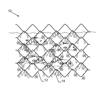
[0039] Figure 1 shows an aquaculture net 10 whereby the steel wires 12 of the
mesh structure are overgrown with bio-fouling organisms 14, such as
barnacles, algae or molluscs that attach to the net. The fouling mechanism
may be so persistent that entire openings in the meshes may be filled
blocking any introduction of fresh water or nutrition into the volume inside
the mesh structure.
[0040] Figure 2 shows a cross section of a steel wire 12 according to the
invention. A metal coating 16 is welded to or around a steel core 14.
[0041] A known problem with welding a metal coating to a steel core is
adhesion.
[0042] Several processes and materials have been used to increase clad wire
adhesion.
[0043] In the context of the present invention, the term "cladding" means the
process of providing a coating around a steel core in the form of a strip or
a foil and fixing this to the steel core by means of welding or by means of
drawing.
[0044] Figure 3a shows an example of bad adhesion whereby a metal coating 16
is welded to a steel core 14 by means of a welding zone 18 leaving gaps
20 and 22 in the welding zone.
[0045] Figure 3b shows an example of good adhesion whereby gaps 20 and 22
are avoided.
CA 02705892 2010-05-14
WO 2009/095135 PCT/EP2008/067553
8
[0046] In one process clad wire adhesion was increased by using Turks heads at
high temperature. Turks heads were applied just after the welding table to
press the coating onto the core wire at a minimum temperature of 200
degrees C. All cross sections showed perfect adhesion. After combining
with drawing in one die pass, no gaps were seen at the interface, even at
the welding zone. The composite could be drawn at least 10% more in
diameter directly in the cladding line. Characteristic voids or gaps at the
welding zone were not observed during the further drawing.
[0047] In another process adhesion is increased by choosing material with
different crystallographic structure for the steel core and the metal coating.
Figure 4b shows an example of good mechanical adhesion for a steel core
with a body centered cubic structure and a metal coating with a face
centered cubic structure. In contrast with Figure 4b, Figure 4a shows a
cross-section of a steel core and metal coating where both have a face
centered cubic structure. The interface between the steel core and the
coating has a surface area that is smaller than that of Figure 4b, hence
providing less adhesion between the two materials.
[0048] In yet another process adhesion is increased by annealing at an
appropriate temperature. Tests have been performed at different
temperatures. Figure 5 shows the effect of annealing for 2 hours at 1070
degrees C. A significant enrichment in Ni is observed towards the outer
surface of a stainless steel core 14. In other words, a gradient in Ni close
to the interface between said steel core and said metal coating is noticed.
This improves adhesion between the stainless steel core 14 and the metal
coating 16.
[0049] In a fourth process adhesion is increased by increasing the hardness
and
improving the surface quality of the inner wire. As mentioned a hard
drawn wire as starting core material yields better adhesion, compared to a
rod as starting material.
CA 02705892 2010-05-14
WO 2009/095135 PCT/EP2008/067553
9
[0050] Clad wire adhesion can be measured by means of indirect methods, such
as by cutting the composite wire with pliers or others and observing the
ends.
[0051] Another indirect method is by following up the corrosion at the cut
ends in
a hot sea water test. Bad adhesion has a direct impact on cut end
corrosion. Yet another indirect method is by optical microscopy and cross
section roughness measurements. A fourth indirect method is by SEM and
EDXS to check the diffusion.
[0052] Figure 6 shows the process of welding a metal coating 16 to a steel
core
14. A strip of a suitable metal 16 and predetermined thickness can be
formed into a tube form. The width of this strip is somewhat greater or
equal to the circumference of the steel core 14 to be covered. The strip is
closed in a tube and welded around the steel core. After welding, Turks
heads 60 press the metal coating 16 to the steel core 14.
[0053] As such a process is provided wherein a metal coating of predefined
composition and thickness is applied to a steel core wire. Said metal
coating is a copper nickel alloy. The metal coating is welded around or on
a steel wire core.
[0054] Preferably the process step of welding may be preceded by a step of
drawing the steel wire in order to provide a steel wire with increased
hardness and with increased tensile strength.
[0055] Preferably the process step of welding may be followed by a step of
pressing the coating against the steel core by means of Turks heads at a
minimum temperature of 200 degrees Celsius.
[0056] Alternatively or additionally, the process step of enclosing the steel
core
with a strip or foil of metal may be followed by a step of annealing the steel
core with the metal coating at a temperature above 950 C for a time
period of at least one hour.