Note: Descriptions are shown in the official language in which they were submitted.
CA 02706572 2010-05-21
Agent Ref: 75148/00004
1 Dosing Device for the Inhalation of a Powder Substance
2
3 The invention relates to a metering device which can be activated by the
user's suction
4 airstream and is intended for the inhalation of a pulverulent substance,
in particular a medicinal
substance, according to the preamble of the main claim.
6
7 A metering device of the type in question is known from WO 2006/021546
Al. The quantity of
8 substance separated off in the metering chamber is moved into a closed
emptying-standby
9 position. As a result of a user breathing in, a piston moves and opens
the metering chamber.
Thereafter, the latter is connected to an air-flow path for clearing the
separated-off quantity of
11 substance out of the metering chamber and transferring it into the
airstream which is to be
12 sucked in.
13
14 In view of this known prior art, it may be considered to be a technical
problem of the invention to
develop in an advantageous manner a metering device of the type in question in
respect of
16 optimum air channeling. WO 02/26299 has already proposed to use the
suction airstream both
17 for displacing a metering rod and for conveying the substance through
the mouthpiece. These
18 solutions, however, can only be used with the metering device in the
upright position, that is to
19 say they cannot be used, in practice, when the user is lying in bed.
There is also a risk of the
inhaler-substance mixture separating.
21
22 The problem of optimum air channeling is solved substantially by the
subject matter of Claim 1.
23 Two airstreams meet in an annular chamber, one of the airstreams
initially opening the metering
24 chamber and then coming into contact with the other airstream in the
annular chamber. The
configuration selected for the piston means that only a relatively low mass
needs to be shifted
26 when the piston is displaced, but a large-area engagement surface is
provided, and this makes
27 it easier for the piston to be moved out of the emptying-standby
position into the emptying-
28 release position by means of the user's suction airstream. Accordingly,
only a relatively low level
29 of suction airstream energy is required in order to release the metering
chamber. Furthermore,
the narrow construction of the piston makes it possible to achieve increased
levels of air energy
31 during inhalation.
32
33 In an advantageous development, it is provided that, in its upper end
position, the upper
34 periphery of the piston engages in front of an annular wall, which
belongs to an annular
21997294.1 1
CA 02706572 2010-05-21
Agent Ref: 75148/00004
1 chamber, and preferably the ceiling of the latter has peripherally
extending, projecting wings
2 which leave intermediate spaces between them. Disposed downstream of the
same is a ceiling
3 portion which constitutes an oblique deflecting wall with concentrating
action. Further preferably,
4 the piston, which has air flowing around it during inhalation, i.e.
during suction-air activation by
the user, releases the path to the annular chamber in the upper position, i.e.
in the emptying-
6 release position of the metering chamber, with sealing engagement against
the annular wall of
7 the annular chamber. The annular chamber acts in the manner of a vortex
chamber, in which
8 the powder which is to be inhaled is distributed optimally in the suction
air. The powder which is
9 to be inhaled consists, for example, of a basic body, such as lactose,
which can be transported
by a suction stream and is suitable as a carrier for fine micronized drug
particles adhering to its
11 surface. These basic bodies are usually of different sizes. On account
of the powder-laden
12 suction air flowing through the annular chamber, the particles of powder
are rendered more or
13 less the same size, i.e. relatively large particles of powder are broken
up as a result of the
14 vortexing and the associated centrifugal forces. The powder-laden
suction air is extracted by
suction through the intermediate spaces which are formed between the wings
extending radially
16 outward from the cover and from where the suction air passes, in
slightly concentrated form,
17 into the mouthpiece of the metering device. It is possible to
distribute, over the circumference of
18 the cover, wings and interspaces of the same width, as seen in the
circumferential direction.
19 However, it is also possible to provide wings and/or interspaces of
different widths in the
circumferential direction. This creates at the end of the annular chamber, as
seen in the
21 direction in which flow takes place around the annular chamber, forced
guidance of the powder-
22 laden airstream, through an interspace provided correspondingly on the
cover, into the
23 mouthpiece. In a development of the subject matter of the invention, it
is provided that some of
24 the wings are of circumferentially wider configuration, in order to form
a deflecting-wall wing for
the powder-laden suction airstream. This wing is preferably directed, in first
instance, in the axial
26 direction of the annular chamber. The deflecting-wall wing forces the
incoming suction airstream
27 to deflect into a plane of circulation directed transversely to the
annular chamber. By virtue of
28 the deflecting-wall wing being acted upon at relatively high speed,
relatively large particles of
29 powder are broken up. The metering rod is retained in an inner cylinder,
which can be rotated
by the closure cap, such that it can be displaced along the axial extent of
the inner cylinder. The
31 rotation of the inner cylinder is transmitted to the metering rod. This
inner cylinder is provided,
32 on the lateral-wall side, with an axially running channel which extends
from the emptying side of
33 the metering chamber and terminates in the annular chamber, the
deflecting-wall wing being
34 provided in order to deflect the axial airstream direction into the
orbital plane. Accordingly, this
21997294.1 2
CA 02706572 2010-05-21
Agent Ref: 75148/00004
1 deflecting-wall wing is disposed in the manner of a cover in axial
extension of the channel, with
2 the radial outlet being left in the process. Via this channel, following
the suction-air-induced
3 raising operation of the piston and the associated release of the
metering chamber, the
4 separated-off dose of substance is sucked out and fed, via the annular
chamber, to the user
who is building up the suction airstream. In a preferred configuration,
deflection from the radial
6 flow direction into the axial flow direction is achieved by two channel
deflection regions which
7 are located directly one after the other and each cause flow to be
deflected by 45 degrees. An
8 intermediate channel portion which runs at an angle of approximately 45
degrees to a plane
9 oriented transversely to the axis of the device, and connects the
emptying side of the metering
chamber to the axially running channel, is thus also preferably provided.
11
12 A total of two air-flow paths are created, of which the one causes the
metering chamber to be
13 emptied and the second leads directly into an annular chamber which is
located upstream of the
14 mouthpiece and where the two airstreams meet. Accordingly, the one
particle-laden airstream
established during the inhalation operation is channeled separately. The
quantity of air which is
16 required for inhalation is fed, in part, via the first air-flow path
within the annular chamber. If the
17 metering chamber is closed, the metering chamber can be opened via this
air-flow path, for
18 example via the suction-air-activated piston. By virtue of the air-flow
paths being separated, a
19 stream of air which is not laden with particles is formed initially. In
the event of correct
inhalation, approximately 50 liters of air per minute flow through the device,
which quantities of
21 air result from at least the two airstreams being added together, one
fraction being fed, in first
22 instance, via the first flow path, which opens the metering chamber. In
a preferred configuration,
23 this opening of the metering chamber, for example by virtue of a piston
being displaced out of
24 an emptying-standby position into an emptying-release position, takes
place at an opening
pressure of approximately 2 kPa, and furthermore with an airflow of 18 to 22
liters of air per
26 minute. The airstream of the second air-flow path, which leads directly
from the metering
27 chamber into the annular chamber, the annular chamber being located
upstream of the
28 mouthpiece, has a significantly higher flow speed than the airstream
which results in the
29 metering chamber being emptied.
31 In a preferred configuration, the second airstream is sucked in through
a grille-wall portion. The
32 latter leaves a free opening cross-section which allows the necessary
quantity of air to be easily
33 sucked in. Further preferably, the air-inlet grille surface is located
on the outer cylinder, which
34 cannot be rotated in relation to the inner cylinder and continues the
closure cap, on that side of
21997294.1 3
CA 02706572 2010-05-21
Agent Ref: 75148/00004
1 the metering rod which is located opposite to the emptying direction of
the metering chamber.
2 This means that there is clear structural separation of the air-flow
paths.
3
4 A compact construction of such a metering device is further achieved in
that a flow channel
directed toward the metering chamber is disposed beneath the air-inlet grille
surface, even in
6 the position assumed by the metering chamber in an emptying-standby
position, and this flow
7 channel even allows a visual check as to whether the metering chamber is
full and/or closed. In
8 a preferred configuration, this channel passes through the outer cylinder
beneath the air-inlet
9 grille surface for the first air-flow path in the region of an
appropriately formed air-inlet opening.
As a result of this configuration, the two air-flow paths open, in respect of
the air-inlet openings,
11 to the same side of the outer cylinder. Via the flow channel provided
beneath the air-inlet grille
12 surface, in the emptying-release position, the metering chamber is
cleared preferably
13 transversely to the device axis in order for the separated-off substance
to be transported via the
14 second air-flow path, passing through the annular chamber into the
mouthpiece, all this being as
a consequence of suction-air activation on the part of the user. In a further-
preferred
16 configuration, the interior of the inner cylinder is available entirely
for the free distribution of the
17 air sucked in through the air-inlet grille surface, and it is in flow
connection with the annular
18 chamber.
19
In a further configuration of the invention, the lateral wall of the outer
cylinder has at least one
21 air-inlet opening, preferably two radially opposite air-inlet openings.
Further air-flow paths are
22 achieved via these separate air-inlet openings, these further air-flow
paths being separated from
23 the other two air-flow paths at least in the emptying-standby position.
It is thus provided, in an
24 advantageous development of the subject matter of the invention, that
the air-inlet openings
open out in a tangentially directed manner into the annular chamber, a common
flow direction
26 being predetermined in the process, this further being a flow direction
which is even
27 predetermined by the other two air-flow paths. These air-inlet openings
achieve a kind of initial
28 ignition in order to deflect the rest of the air-flow paths in the
desired flow direction within the
29 annular chamber.
31 The substance which is to be inhaled is stored in a storage chamber,
into which the metering
32 chamber penetrates for filling purposes. In order to assist the filling
operation of the metering
33 chamber here, and furthermore to achieve the situation where the
uppermost layer of the
34 substance store, which has the metering chamber passing through it, is
always loosened, a
21997294.1 4
CA 02706572 2010-05-21
Agent Ref: 75148/00004
1 rotor-like blade is retained on the lower periphery of the inner
cylinder, for example clipped
2 thereon, which blade interacts with an inwardly directed stator-like
shoulder of the storage-
3 chamber wall. This allows the replenishment and the density of the
substance in the storage
4 chamber to be kept constant. Added to this is a loosening effect which is
provided in the area
surrounding the metering chamber and prevents fractions of the substance from
coming to a
6 halt. Furthermore, the rotor, in interaction with the stator, is
configured such that, when the rotor-
7 like blades are moved back when the closure cap is replaced and screwed
on and the metering
8 chamber is lowered into the storage chamber, the uppermost substance
layer is subjected to
9 slight contact pressure, in order thus to provide, in the storage
chamber, an evened-out
uppermost substance-quantity region associated with the metering chamber.
11
12 Finally, it has also proven to be advantageous to provide, in the region
of the storage-chamber
13 wall, a filling-level indicator which makes it possible to ascertain the
amount of filling. In the
14 simplest configuration, this can be coupled directly to the axial
movement of a pressure piston
which is disposed in the storage chamber and subjects the stored quantity of
substance to
16 loading from beneath in the direction of the inner cylinder. This
pressure piston advances as
17 substance is removed, and this can be observed via the filling-level
indicator.
18
19 The invention is explained in more detail hereinbelow with reference to
the accompanying
drawing, which merely constitutes an exemplary embodiment and in which:
21
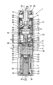
22 Figure 1 shows the vertical section through a metering device
according to the invention
23 in the basic position, with the cap closed;
24
Figure 2 shows a further vertical section along line II-II in Figure 1;
26
27 Figure 3 shows an enlargement of an upper region of the
device according to Figure 1;
28
29 Figure 4 shows a sectional illustration corresponding to
Figure 1, relating to the situation
where the storage chamber for the substance which is to be inhaled has been
31 more or less emptied;
32
33 Figure 5 shows the section along line V-V in Figure 4;
34
21997294.1 5
CA 02706572 2010-05-21
Agent Ref: 75148/00004
1 Figure 6 shows a further illustration corresponding to Figure
1, this time during removal
2 of the closure cap;
3
4 Figure 7 shows the section along line VII-VII in Figure 6;
6 Figure 8 shows the vertical section according to Figure 1,
but following removal of the
7 closure cap and the resulting displacement of a metering chamber
into the
8 emptying-standby position;
9
Figure 9 shows the section along line IX-IX in Figure 8;
11
12 Figure 10 shows a detail-view illustration corresponding to
Figure 3, relating to the
13 situation according to Figure 8;
14
Figure 11 shows a follow-up illustration to Figure 8, but relating to a
position assumed
16 during inhalation;
17
18 Figure 12 shows the section along line XII-XII in Figure 11;
19
Figure 13 shows a further detail-view illustration corresponding to Figure
3, but relating to
21 the situation according to Figure 11;
22
23 Figure 14 shows a further vertical-section illustration
corresponding to Figure 1, this time
24 relating to an intermediate position as the closure cap is being
replaced
following completion of inhalation;
26
27 Figure 15 shows a follow-up illustration to Figure 14,
relating to an intermediate position;
28
29 Figure 16 shows a follow-up illustration to Figure 15,
relating to an intermediate position
as the operation of screwing on the closure cap continues;
31
32 Figure 17 shows the cross-section through the metering device
in the emptying-standby
33 position along line XVII-XVII in Figure 8;
34
21997294.1 6
CA 02706572 2010-05-21
Agent Ref: 75148/00004
1 Figure 18 shows the cross-sectional illustration through the
metering device along line
2 XVIII-XVIII in Figure 11;
3
4 Figure 19 shows an illustration which corresponds to Figure
17 and has been taken along
line XIX-XIX in Figure 11, relating to the emptying-release position;
6
7 Figure 20 shows the section along line XX-XX in Figure 11
through the storage chamber,
8 with the substance which is stored here having been left out;
9
Figure 21 shows a perspective detail illustration of an inner cylinder of
the metering
11 device;
12
13 Figure 22 shows a further perspective illustration of the
inner cylinder;
14
Figure 23 shows a perspective detail illustration of the metering rod of
the metering
16 device;
17
18 Figure 24 shows a perspective detail illustration of the
piston;
19
Figure 25 shows a further perspective detail illustration of a rotor-like
blade for disposing
21 on the inner cylinder;
22
23 Figure 26 shows a further perspective illustration of the
rotor-like blade; and
24
Figure 27 shows, in a detail drawing, the bottom view of a cover of an
annular chamber.
26
27 The metering device 1 which is illustrated in the figures and is
intended for the inhalation of a
28 pulverulent substance 2, in particular a medicinal substance, is
realized as a short-elongate
29 device which can readily be carried in a pocket and has a cylindrical
housing 3 which
determines its shape.
31
32 The cylindrical, tube-like housing 3 has, at the head end, an outer
cylinder 4 which can be
33 rotated about the device axis x relative to the housing 3. This outer
cylinder is secured in a
34 rotatable manner on the housing 3 in the region of an end-side radial
step 5.
21997294.1 7
CA 02706572 2010-05-21
Agent Ref: 75148/00004
1
2 This likewise cylindrical, tube-like outer cylinder 4 merges, at the head
end of the device 1, into
3 an attached mouthpiece 6 which is formed appropriately for the mouth, for
example is flattened.
4 This mouthpiece 6 can have a cup-like closure cap 7 engaging over it in a
protective manner.
This closure cap is realized as a screw cap, for which reason an associated
internal thread 8
6 engages in a corresponding external thread 9 on the lateral wall of the
housing 3.
7
8 The outer cylinder 4 is connected to the closure cap 7 in a rotationally
fixed manner, for which
9 reason the outer cylinder has, on the outside of its lateral wall,
vertically oriented ribs 10 which
interact with correspondingly positioned, slot-like vertical grooves 11 on the
inside of the wall of
11 the closure cap 7. Accordingly, screw-action actuation of the closure
cap 7 causes the outer
12 cylinder 4 to be rotated about the device axis x.
13
14 At the foot end, the end periphery of the cup-like closure cap 7 engages
in a stop-limiting
manner, and with sealing via a cone, against an annular shoulder 12, which is
achieved on
16 account of the abovementioned step of the cylindrical housing 3.
17
18 The closure cap 7 serves, at the same time, as an actuating handle 13
for dispensing the
19 pulverulent substance 2 in reproducible sub-quantities 14, for which
purpose use is made of the
axial screw-action displacement provided by the threaded engagement between
the internal
21 thread 8 and external thread 9. The substance 2 is accommodated
(possibly such that it can be
22 refilled) in a storage chamber 15 of the housing 3. A metering device
conveys a respective sub-
23 quantity 14 of substance to a transfer location U located outside the
storage chamber 15.
24
The meterable substance is a (usually medicinal) pulverulent substance 2. It
is possible for
26 basic bodies such as lactose, which are capable for example of
transporting a suction stream, to
27 be carriers for fine micronized drug particles adhering to the surface.
28
29 The storage chamber 15 is terminated at the bottom by a cup-like
pressure-exerting base 16,
which is spring-loaded in the direction of the mouthpiece 6 by means of a
compression spring
31 17. The compression spring 17 has its foot-side end turn supported on a
base cap 18, which
32 closes the housing 3 there. This base cap is in latching engagement with
that portion of the
33 housing 3 which is of larger cross-section here on its inside wall, a
corresponding latching collar
34 19 of the base cap 18 engaging in a matching annular groove of the
housing 3.
21997294.2 8
CA 02706572 2010-05-21
Agent Ref: 75148/00004
1
2 The head-side end turn of the biased compression spring 17 subjects an
inner shoulder 20 of a
3 hollow piston 21 of the piston-like means 16/21 to loading action. As can
be seen from the
4 illustrations, the pressure-exerting base 16, which is in the form of a
graduated cup, is
connected with latching action to the hollow piston 21 in the region of the
inner shoulder 20.
6
7 The cup periphery of the pressure-exerting base 16 forms an annular lip
22 which, on account
8 of its elastomeric material, strips substance off the wall of the storage
chamber 15 without
9 leaving any residues.
11 In the exemplary embodiment illustrated, the compression spring 17 is a
cylindrical spring
12 which, in the state in which it is relieved of stressing, has a length
corresponding approximately
13 to ten times the maximum contact-pressure length. The contact-pressure
length is defined by
14 the extent of axial displacement of the pressure-exerting base 16
between a lower position
according to Figure 1, this position corresponding to the filling position,
and an upper, stop-
16 limited position of the pressure-exerting base 16 in the storage chamber
15 according to Figure
17 4. Thus, the exemplary embodiment illustrated provides a contact-
pressure length of 15 mm. As
18 a result of the configuration of the spring, in particular as a result
of the selected length of the
19 spring, the pressure-exerting base 16 is subjected to a constant spring
pressure over the entire
contact-pressure length, and this leads to the substance being compressed
uniformly
21 throughout the duration of use of the device 1.
22
23 A hollow upright stub 23 extends centrally from the base cap 18.
Together with the hollow piston
24 21 which encloses it at a distance apart, this hollow upright stub forms
a chamber 24 for the
compression spring 17. The hollow upright stub 23 contains, in its center, a
moisture-absorbing
26 material in the form of a drying-agent capsule 25. At the transition to
the outer cylinder 4, which
27 follows the housing 3 in the axial direction, the storage chamber 15
terminates with a chamber
28 ceiling 26 formed integrally with the lateral wall of the storage
chamber 15. Passing through the
29 center of this chamber ceiling is a cylinder portion 27 of a rotary part
28 which extends in a
plane perpendicular to the device axis x. This rotary part is of substantially
plate-like
31 configuration and is connected in a rotationally fixed manner to the
outer cylinder 4 and,
32 accordingly, can be rotated about the device axis x in relation to the
chamber ceiling 26. The
33 cylinder portion 27 extends on the underside of the rotary part 28,
passing through the chamber
21997294.2 9
CA 02706572 2010-05-21
Agent Ref: 75148/00004
1 ceiling 26. The lower free end surface of the cylinder portion 27 is
located in the plane of that
2 surface of the chamber ceiling 26 which covers the storage chamber 15.
3
4 The diameter of the through-opening in the chamber ceiling 26 is larger
than the diameter of the
cylinder portion 27. A holder, of annular shape in plan view, for a rotor
blade R, is positioned in
6 the annular gap which remains. This rotor blade is connected in a
rotationally fixed manner to
7 the cylinder portion 27.
8
9 The inner surface of the rotor ring 30, this inner surface being directed
toward the storage
chamber 15, is located in the plane of the correspondingly directed end
surface of the cylinder
11 portion 27.
12
13 The rotor R, which is illustrated on its own in Figures 25 and 26,
carries on the underside, that is
14 to say in the direction toward the storage chamber 15, a blade 29. This
is a blade 29 which is in
the form of a spherical-cap portion and projects radially outward beyond the
ring 30 of the rotor
16 R. The blade 29 correspondingly engages beneath that region of the
chamber ceiling 26 which
17 adjoins the rotor R radially on the outside, that surface of the blade
29 which is directed toward
18 the chamber ceiling 26 being of planar configuration. This surface of
the blade 29 engages
19 against the top surface of the chamber which is directed toward the
blade. The blade 29
extends radially as far as the inner wall of the storage chamber 15. From this
radially outer
21 region, the blade 29 slopes up convexly in the radially inward
direction, as seen in cross-
22 section, to an axial height corresponding approximately to the extent by
which the blade 29
23 projects radially beyond the rotor ring 30.
24
As a result of this arrangement, the blade 29 of the rotor R projects into the
substance stored in
26 the storage chamber 15. The shoulder formed by the chamber ceiling 26,
in interaction with the
27 blade 29 or rotor R, which can be rotated relative to the storage
chamber 15, forms a stator St.
28
29 The rotor R is clipped on the cylinder portion 27 of the rotary part 28
via the rotor ring 30.
31 The cylinder portion 27 accommodates a sealing bushing 31 in its center.
This bushing consists
32 of a rubber material or a similar elastic material. This leaves, in its
center, a cross-sectionally
33 slot-like guide opening 32 for a cross-sectionally adapted metering rod
33.
34
21997294.2 10
CA 02706572 2010-05-21
Agent Ref: 75148/00004
1 In the simplest configuration, the sealing bushing 31 and also an annular
seal 35 provided
2 between the rotary part 28 and a housing portion 34, which engages over
the chamber ceiling
3 26 on the housing side, may be produced by two-component injection
molding together with the
4 rotary part 28 and, furthermore, with an inner cylinder, which will be
described in more detail. It
is also possible in this respect, however, for the rubber or elastomer parts
to be provided
6 subsequently during production.
7
8 At the foot end, the hollow piston 21, which is connected with latching
action to the pressure-
9 exerting base 16, has a radial extension arm 36. Integrally formed on the
latter is an axially
oriented indicating protrusion 37 which engages over the storage-chamber wall
on its outside.
11 The axial position of this indicating protrusion, this position being
reached in dependence on the
12 position of the pressure-exerting base, can be seen by the user from the
outside through a
13 viewing window 38 provided in the housing. A filling-level indicator 39
is provided as a result.
14
The metering rod 33 is appropriately configured for functioning as a moving
metering chamber
16 40 for the sub-quantity 14 of substance which is to be dispensed, the
metering rod 33 moving
17 linearly along the longitudinal center axis x-x of the substantially
rotationally symmetrical device
18 1, and this being accompanied by a rotary movement executed about the
longitudinal center
19 axis x-x. The metering rod 33 is formed substantially as a flat part
with an elongate-rectangular
cross-section. The length ratio of narrow side to broad side is approximately
1:3 in the
21 exemplary embodiment illustrated.
22
23 At the end which is directed away from the mouthpiece 6, the metering
rod 33 forms a portion
24 which tapers to a point more or less in the manner of a cross-recessed
screwdriver tip. The two
mirror-symmetrical oblique flanks here extend from the respective broad sides
of the metering
26 rod 33 (cf. Figure 20).
27
28 On account of the metering rod 33 being carried along in rotation, the
cross-sectional
29 configuration of the metering rod 33 and the tapering of the free end
region have a loosening,
displacing effect in the central region in relation to the mass of pulverulent
substance 2.
31
32 The metering chamber 40 is realized as a transverse hole which runs
substantially
33 perpendicularly to the longitudinal center axis x-x and has an axis
which passes through the
34 broad-side surfaces of the metering rod 33. The transverse hole is
formed conically, so that the
21997294.1 11
CA 02706572 2010-05-21
Agent Ref. 75148/00004
1 transverse hole tapers in the direction of one broad-side surface of the
metering rod 33.
2 Furthermore, as can be seen for example from the illustration in Figure
2, the metering chamber
3 40, which is formed in the region of that end of the metering rod 33
which projects into the mass
4 of substance, is disposed eccentrically in relation to the broad-side
surfaces of the metering rod
33, that is to say it is offset laterally in relation to the longitudinal axis
x-x.
6
7 The displacement path of the metering chamber 40, which moves linearly,
and, at the same
8 time, in rotation, allows, in both end positions of the metering rod 33,
for the cross-section of the
9 guide opening 32 to be kept closed, with metering-chamber-filling
scraping or stripping action
over the length of the said opening 32.
11
12 The mouthpiece end of the closure cap 7 forms a docking location 41
between the metering rod
13 33 and closure cap 7, this docking location disengaging when subjected
to overloading. The
14 latching means on the closure-cap side here is a resilient hook annulus
which is formed in the
region of the free end of a hollow cylinder 43 disposed centrally on the
underside of a closure-
16 cap ceiling 42. The corresponding end of the metering rod 33 is
rotationally symmetrical in
17 cross-section, a disk-like radial collar 44, furthermore, projecting out
in the transition region from
18 the flat-part portion to the cylindrical end portion. At an axial
spacing from this radial collar 44,
19 that end region of the metering rod 33 which is directed away from the
flat part forms a latching
head 45. A wasp-waist-like annular groove 46 is formed between this latching
head and the
21 radial collar 44. Inwardly directed noses 47 of the resilient tongues of
the hook annulus engage
22 in this annular groove. The noses 47 can pass over the latching head 45
in both axial directions.
23 The latching action may be fairly tight, since it is released and
reinstated during the screwing-
24 action displacement of the cap.
26 The central opening 48 of the mouthpiece 6 is formed in the region of a
dispersing part 49. This
27 dispersing part 49 opens conically outward, that is to say in the
direction away from the storage
28 chamber 15, the wall 50 of the dispersing part merging, in the direction
toward the storage
29 chamber 15, into an annular, roof-like ceiling portion 51. At the same
time, the latter forms the
upper terminal of the outer cylinder 4, which carries the mouthpiece 6.
31
32 The central free space created by the dispersing part 49 has the hollow
cylinder 43, which
33 carries the noses 47, passing through it centrally in the cap-closed
position. The annular space
21997294.2 12
CA 02706572 2010-05-21
Agent Ref: 75148/00004
1 which forms here between the hollow cylinder 43 and the dispersing-part
wall is filled by a
2 further drying-agent capsule 52 in the cap-closed position.
3
4 The outer cylinder 4 accommodates an inner cylinder 53, passing through
the center of which is
the metering rod 33 and, in the cap-closed position, the hollow cylinder 43
belonging to the
6 closure cap. The inner cylinder is connected in a rotationally fixed
manner to the outer cylinder
7 4.
8
9 This inner cylinder 53 is configured substantially as a hollow body and
carries, in its center, an
axially displaceable piston 54. The piston 54 is guided more or less in the
lower half of the inner
11 cylinder 53, directed toward the storage chamber 15, by a cross-
sectionally round guide portion
12 55.
13
14 That portion of the inner cylinder 53 which is directed away from the
storage chamber 15 forms
a piston-head displacement region 56 which has a cross-section larger than
that of the guide
16 portion 55 and of which the axially oriented wall 57 has radial openings
58, 58' and 58". These
17 radial openings are in flow connection with a grille-wall portion 59 of
the outer cylinder.
18
19 Formed beneath the grille-wall portion 59, and furthermore at the foot
end of the guide portion
55 of the inner cylinder, is a radially oriented flow channel 60, which
likewise opens toward the
21 grille-wall portion 59. This flow channel may also serve as a window for
visually monitoring the
22 metering rod 33. It opens out into the free space left in the center by
the guide portion 55.
23 Radially opposite the flow channel 60, the guide portion 55 is adjoined
by an intermediate
24 channel portion 61 which, starting from the guide portion 55, and with
the inclusion of an angle
of 450 in relation to a plane oriented perpendicularly to the axis x, slopes
up in the direction of
26 the associated wall of the outer cylinder 4 in order then to merge, at
the end, into an axially
27 directed channel 62. This channel 62 is formed by an axially oriented,
slot-like, radially
28 outwardly opening recess in the lateral surface of the inner cylinder.
The channel 62 is covered
29 over radially by the associated wall of the outer cylinder 4.
31 As well as the radial opening 58, which can be seen by way of example in
the sectional
32 illustration in Figure 1, two further radial openings 58' and 58" are
provided, and these each
33 enclose, as seen in a plane oriented transversely to the axis x, an
angle of 90 in relation to this
21997294.1 13
CA 02706572 2010-05-21
Agent Ref: 75148/00004
1 radial opening 58 and, by virtue of the inner-cylinder wall being
configured appropriately, are in
2 direct air-flow connection with the grille-wall portion 59.
3
4 The axially oriented channel 62 has its end which is directed toward the
mouthpiece 6 opening
out into an annular chamber 63. The latter forms a vortex chamber. The ceiling
64 of the latter is
6 of cross-sectionally roof-like configuration and is provided with
peripherally extending, projecting
7 wings 65, 66. These engage peripherally against the inner wall of the
outer cylinder 4 and, as
8 seen in the circumferential direction, leave intermediate spaces 67
between them, through
9 which an air-flow connection is achieved between the annular chamber 63
and a further annular
space 68 left between the dispersing-part ceiling portion 51 and the annular-
chamber ceiling 64.
11
12 The ceiling 64 is secured on the inside wall of the inner cylinder 53 by
an axially directed flange
13 69.
14
The base of the annular chamber 63 is formed by an annular collar 70 which
projects radially
16 outward on the outside wall of the inner cylinder 53 at an axial spacing
from the wings 65, 66 of
17 the ceiling 64. It is also the case that this annular collar is
supported peripherally on the inside
18 wall of the outer cylinder 4. This annular collar 70 is interrupted by
the axially oriented channel
19 62. The annular chamber 63 is bounded in the radially inward direction
by an end-side wall
portion which belongs to the inner cylinder 53 and serves for latching the
ceiling 64. The
21 resulting annular-chamber wall is provided with slot-like through-
passages 71 in order to provide
22 air-flow connection between the annular chamber 63 and the piston-head
displacement region
23 56.
24
As can furthermore be seen, in particular, from the sectional illustration in
Figure 18, the outer-
26 cylinder wall is provided, level with the annular chamber 63, with two
diametrically opposite air-
27 inlet openings 72. These open out tangentially into the annular chamber
63, and this,
28 furthermore, predetermines a common flow direction. Accordingly, a
sucking-in action through
29 the air-inlet openings 72 results in a predetermined air flow in the
annular chamber 63. The
axially oriented channel 62 opens out, as seen in the flow direction,
immediately downstream of
31 the mouth of one air-inlet opening 72 in the annular chamber 63, so that
the airstream entering
32 into the annular chamber 63 through the axial channel 62 is deflected
specifically in the desired
33 vortexing direction via the air-inlet openings 72.
34
21997294.1 14
CA 02706572 2010-05-21
Agent Ref: 75148/00004
1 The wings of the ceiling 64 are of different widths as seen in the
circumferential direction. Thus,
2 two diametrically opposite wings 65 are approximately three times the
width of the rest of the
3 wings 66, as seen in the circumferential direction. One of these broader
wings 65 covers over
4 the mouth region of the axial channel 62 into the annular chamber 63 and,
accordingly, forms a
deflecting-wall wing 73 for the suction airstream entering into the annular
chamber 63 through
6 the axial channel 62.
7
8 As can further be seen, in particular, from the illustration in Figure
27, the wings 66 extend
9 circumferentially, in the exemplary embodiment described, over an angle
13 of 15 . The
intermediate spaces 67 left between the wings 66 and 65 likewise extend
circumferentially over
11 an angle a of 15 , while the peripheral edges of the broader wings 65
enclose an angle 8 of 45 .
12
13 Other distributions are also possible in this respect (for example
smaller wings ¨ larger
14 intermediate spaces; larger wings ¨ smaller intermediate spaces;
irregular configuration of
wings and intermediate spaces).
16
17 An interrupter 74 is disposed in the annular chamber 63 adjacent to the
mouth of the axial
18 channel 62 in the annular chamber 63, the interrupter being in the
airflow direction through the
19 air inlet openings 72. This interrupter limits the circumferential path
of the annular chamber 63
and, accordingly as a result of this configuration, this path is of an
interrupted form rather than
21 being annular throughout. The rear flank of the interrupter 74, this
flank being oriented counter
22 to the flow direction, constitutes a run-on slope 75, connecting the
annular-chamber base to the
23 annular-chamber ceiling, which contains the intermediate spaces 67. This
causes the airstream
24 in the end region of the annular chamber 63 to be forcibly deflected
axially upward into the
further annular space 68.
26
27 The piston 54, which is retained in a rotationally fixed, but axially
displaceable manner, in the
28 inner cylinder 53, has, in first instance, a piston head 76 which opens
in disk form in the
29 direction of the mouthpiece. This piston head opens conically in cross-
section. Two parallel,
axially oriented tongues 77 are integrally formed on the underside of the
piston disk. The piston
31 54 consist of a rubber-like material.
32
33 Along their lower free periphery, the tongues 77, which accommodate the
cross-sectional
34 contour of the guide portion 55 of the inner cylinder 53 on their
outside wall, are split in a lip-like
21997294.1 15
CA 02706572 2010-05-21
Agent Ref: 75148/00004
1 manner and, furthermore, in their free peripheral region, they have
material-reinforced sealing
2 surfaces 78.
3
4 The flat part of the metering rod 33 is guided between the tongues 77,
the sealing surfaces 78,
in interaction with the flat part of the metering rod 33, having a stripping
and sealing action.
6
7 In a basic position of the device according to the illustration in Figure
1, the free peripheries of
8 the tongues 77, these peripheries being split in a lip-like manner,
engage, within an axial
9 depression, against the upper side of the cylinder portion 27.
11 Furthermore, in this basic position, the disk-like piston head 76 rests
in a stop-limited manner on
12 a base region of the piston-head displacement region 56. The encircling
peripheral region of the
13 free end of the piston head 76 engages with sealing action against the
associated inner wall of
14 the inner cylinder 53.
16 Furthermore, in this basic position, the head of the metering rod 33,
that is to say the radial
17 collar 44 and latching head 45 of the same, rests in the depression
created by the disk-like
18 configuration of the piston head 76.
19
The piston head 76 here is located at an axial distance beneath the ceiling
64.
21
22 The device 1 cited functions as follows:
23 In order to prepare for inhalation, the closure cap 7 is first of all
removed by unscrewing. As the
24 closure cap 7 is being unscrewed upward, the coupling mentioned results
in the outer cylinder 4
being carried along in rotation and, via this outer cylinder, the inner
cylinder 53 as well as, in the
26 exemplary embodiment cited, all those parts above the storage-chamber
plane which are not
27 connected in a rotationally fixed manner to the housing 3. Accordingly,
the metering rod 33 is
28 also carried along in rotation, and furthermore, the action of the
closure cap 7 being unscrewed
29 upward gives rise, at the same time, to axial displacement of the
metering rod 33 via the
docking location 41, which causes helical displacement of the metering chamber
40 into the as
31 yet closed emptying-standby position B according to the illustration in
Figures 6 and 7, in which
32 it is aligned with the flow channel 60.
33
21997294.1 16
CA 02706572 2010-05-21
Agent Ref: 75148/00004
1 By virtue of the metering chamber 40 being disposed eccentrically in
relation to the axis of
2 rotation of the metering rod 33, it is filled optimally as a result of
penetrating helically through the
3 mass of substance, assisted by the rotor. The larger-diameter opening
surface of the metering
4 chamber 40 here is oriented in the direction of rotation.
6 The simultaneously rotating blade 29 of the rotor R here causes the
surrounding mass of
7 substance to be in a constantly loosened state, a shoveling effect being
achieved. When the
8 rotor R rotates in the opposite direction ¨ as the closure cap 7 is
screwed on again ¨ the blade
9 29 interacts with the stator St in order to scrape off substance 2 from
the surface of the stator
and to press the substance 2 down, as a result of which the mass of substance
is evened out.
11 The blade 29 of the rotor R, accordingly, acts on the mass of substance
in both directions of
12 rotation.
13
14 When the removal-standby position B of the metering rod 33 is reached,
the metering rod is
secured with latching action. For this purpose, the radial collar 44 of the
metering rod 33 moves
16 behind latching fingers 79 which are formed on the underside of the
ceiling 64.
17
18 As the screwing-action displacement of the closure cap 7 continues, the
latching in the region of
19 the docking location 41 between the hollow cylinder 43 and the metering
rod 33 is eliminated.
Accordingly, the noses 47 leave the annular groove 46, whereupon the closure
cap 7 can be
21 removed. The device us now prepared for inhalation.
22
23 The screwing-action displacement of the closure cap 7 makes it possible
to provide sufficient
24 force for producing the latching between the radial collar 44 and
latching fingers 79 and,
furthermore, for eliminating the latching between the latching head 45 and
noses 47 on the cap.
26
27 The tongues 77 of the piston 54 cover over the metering chamber 40 on
each side. Accordingly,
28 in this position, it is not possible for the sub-quantity 14 of
substance to trickle out even in part.
29 Rather, the substance is held reliably captive in the metering chamber
40. This prevents cases
of double metering when inhalation is not carried out, but the device is
closed-off again via the
31 closure cap 7. Furthermore, in the removal-standby position B of the
metering chamber 40, it is
32 also possible for the device 1 to be put to one side. Even if the device
1 experiences normal
33 kinds of impacts, this does not result in the sub-quantity 14 of
substance which is to be inhaled
34 trickling out, which would falsify the inhalation result.
21997294.1 17
CA 02706572 2010-05-21
Agent Ref: 75148/00004
1
2 The inhalation operation takes place automatically by the user subjecting
the device to suction
3 air, in the simplest case by the user breathing in.
4
Air is sucked in via the mouthpiece 6, and this, in first instance, by virtue
of the piston head 76
6 being subjected to the action of air, results in the piston 54 being
displaced axially in the
7 direction of the ceiling 64. In the case of the exemplary embodiment
illustrated, the pressure
8 required to trigger the device is approximately 2 kgPa. Triggering takes
place, as far as
9 possible, in abrupt fashion.
11 In the raised position, the upper free peripheral region of the piston
head 76 engages against
12 the underside of an annular wall 80 of the ceiling 64. The annular space
of the inner cylinder 53
13 which then encloses the free peripheral region of the piston head 76 is
widened radially, as a
14 result of which radial flow takes place around the piston 54 in the
region of the piston head 76.
This gives a main airstream a which flows through the grille-wall portion 59,
passing through the
16 radial openings 58, 58' and 58", into the piston-head displacement
region 56 and passes, by
17 way of the annular-space region left radially outside the piston head
76, through the openings
18 71 into the annular chamber 63. Approximately 85 to 90% of the total
inhalation air volume is
19 transported via this air-flow path.
21 At the same time, via the always open radial air-inlet openings 72, air
is sucked in directly into
22 the annular chamber 63, in order to predetermine the vortexing direction
in the annular chamber
23 63.
24
By virtue of the axially displaced piston 54, the tongues 77 are likewise
displaced axially, in
26 order to release the metering chamber 40. The axial displacement of the
piston 54 is assisted
27 by the guide portion 55, which accommodates the tongues 77, widening
slightly in the direction
28 of the piston head 76, as a result of which there is a reduction in the
friction between the
29 tongues 77 and the wall of the guide portion 55. It is also the case
that the friction between the
tongues 77 and the flat part of the metering rod 33 is minimized, being on the
region of the
31 sealing surfaces 78.
32
33 The metering chamber 40 is then located in a removal-release position F,
in which it lies freely
34 in the flow path between the flow channel 60 and intermediate channel
portion 61. In the
21997294.2 18
CA 02706572 2010-05-21
Agent Ref: 75148/00004
1 exemplary embodiment illustrated, approximately 10 to 15% of the
inhalation air volume is
2 transported via this substance-transporting airstream b.
3
4 The metering chamber is cleared out with through-suction from the flow
channel 60, this,
furthermore, taking place from the smaller opening surface in the direction of
the larger opening
6 surface of the metering chamber 40. The two-fold deflection through in
each case approximately
7 45 into the angled intermediate channel portion 61 and, from the latter,
into the axially oriented
8 channel 62 results, in the manner of a baffle-plate effect, in the
initial breaking up of relatively
9 large particles of powder, which further leads to an improved inhalation
result.
11 The substance-laden airstream flowing axially, at relatively high speed,
into the annular
12 chamber 63 via the channel 62 is deflected via the deflecting-wall wing
73 and, assisted by the
13 initial flow by way of the radial air-inlet openings 72, in the
circumferential direction. Relatively
14 large particles of powder are further broken up on this deflecting-wall
wing 73.
16 As a result of this configuration, the substance-laden airstream is
guided outside the piston
17 region. The piston 54 merely has powder-free air flowing around it.
18
19 Optimum distribution of the sub-quantity 14 of substance which is to be
inhaled is achieved in
the annular chamber 63. The substance-laden air passes out through the
intermediate spaces
21 67 for inhalation. Relatively heavy particles of powder which have
possibly not been broken up,
22 or have not been sufficiently broken up, are directed into the annular
space 68 at the latest via
23 the interrupter 74.
24
In the annular chamber 63, the initially substantially axially inflowing
airstreams a and b are
26 directed in a common horizontal direction of circulation in order then
to pass jointly into the
27 mouthpiece 6, with axial passage through the ceiling 64.
28
29 A number of features are provided in order to indicate successful
inhalation to the user. In first
instance, a visual check can be carried out in that the piston 54, once raised
by suction air, is
31 retained in its raised position on account of the, albeit low,
frictional forces present. The piston
32 54, or the tongues 77 thereof, can be seen in the removal-standby
position B through the
33 radially outwardly open flow channel 60. This can be further assisted by
the tongues 77 being
34 conspicuously colored. Once inhalation has taken place and the piston 54
has been raised
21997294.1 19
CA 02706572 2010-05-21
Agent Ref: 75148/00004
1 correspondingly, the tongues 77 cannot be seen. Rather, there is a free
view of the empty
2 metering chamber 40. It is also the case that the action of the piston 54
striking against the
3 underside of the sealing 64 can be sensed both acoustically and by touch.
4
Once inhalation has taken place, and alternatively also if it is not desired
to effect inhalation
6 from the removal-standby position B, the closure cap 7 is screwed on
again, the latching
7 between the radial collar 44 and the latching fingers 79 being eliminated
in first instance by
8 virtue of the latching head 45 being acted upon by the noses 47. The
retaining forces of this
9 latching connection are of a correspondingly smaller magnitude than the
amount of force which
is necessary for deflecting the noses 47. As the action of screwing the
closure cap 7 downward
11 continues, the radial collar 44 on the metering rod displaces the piston
54 back again into its
12 basic position. At the same time, with axial displacement and
corresponding rotary movement,
13 the metering rod 33 is displaced downward into the storage chamber. The
action of the piston
14 54 being displaced back via the metering rod 33 terminates with the free
ends of the tongues
77, which are formed in the manner of lips, striking against the facing
ceiling surface of the
16 cylinder part 27. As the downward-screwing displacement continues,
finally the noses 47 enter
17 into the annular groove 46 of the metering rod 33. This final latching
action is discernable to the
18 user acoustically and by touch, to indicate that the closing operation
is at an end. It is thus also
19 ensured that a latching action between the metering rod 33 and closure
cap 7 which causes the
metering rod 33, and thus the metering chamber 40, to be carried along into
the removal-
21 standby position B is only achieved in the lowermost position of the
metering rod 33, in which
22 position the metering chamber 40 is filled. Accordingly, there is always
a filled metering
23 chamber 40 available when the metering rod 33 is raised.
24
Incorrect operation is reliably avoided. Improper closure of the device 1
means that, during the
26 next attempt at inhalation, the metering rod 33, which has accordingly
not been raised, on the
27 one hand closes the passage between the flow channel 60 and intermediate
channel portion 61
28 by way of its flat-part portion. It is also the case that the metering
rod 33 continues to act on the
29 associated surface of the piston head 76 via the radial collar 44.
Accordingly, when an attempt
is made at inhalation, the closure of the flow channel 60 and the blocking of
the piston 54
31 means that it is not possible to build up any air flow (with the
exception of the small amount of
32 flow via the small radial air-inlet openings 72). This clearly signals
incorrect positioning to the
33 user. This can only be eliminated by the device 1 being properly closed.
34
21997294.1 20
CA 02706572 2010-05-21
Agent Ref: 75148/00004
1 All features disclosed are (in themselves) pertinent to the invention.
The disclosure content of
2 the associated/attached priority documents (copy of the prior
application) is hereby also
3 included in full in the disclosure of the application, also for the
purpose of incorporating features
4 of these documents in claims of the present application.
21997294.1 21
CA 02706572 2010-05-21
Agent Ref: 75148/00004
1 List of Reference Signs
2
1 Device
2 Substance
3 Housing
4 Outer cylinder
Radial step
6 Mouthpiece
7 Closure cap
8 Internal thread
9 External thread
Ribs
11 Grooves
12 Annular shoulder
13 Actuating handle
14 Sub-quantity of substance
Storage chamber
16 Pressure-exerting base
17 Compression spring
18 Base cap
19 Latching collar
Inner shoulder
21 Hollow piston
22 Annular lip
23 Upright stub
24 Spring chamber
Drying-agent capsule
26 Chamber ceiling
27 Cylinder portion
28 Rotary part
29 Blade
Rotor ring
31 Sealing bushing
32 Guide opening
21997294.1 22
CA 02706572 2010-05-21
Agent Ref: 75148/00004
33 Metering rod
34 Housing portion
35 Annular seal
36 Radial extension arm
37 Indicating protrusion
38 Viewing window
39 Filling-level indicator
40 Metering chamber
41 Docking location
42 Closure-cap ceiling
43 Hollow cylinder
44 Radial collar
45 Latching head
46 Annular groove
47 Noses
48 Mouthpiece opening
49 Dispersing part
50 Wall
51 Ceiling portion
52 Drying-agent capsule
53 Inner cylinder
54 Piston
55 Guide portion
56 Piston-head displacement region
57 Region wall
58 Radial opening
58' Radial opening
58" Radial opening
59 Grille-wall portion
60 Flow channel
61 Intermediate channel portion
62 Channel
63 Annular chamber
64 Ceiling
21997294.1 23
CA 02706572 2010-05-21
Agent Ref: 75148/00004
65 Wing
66 Wing
67 Intermediate spaces
68 Annular space
69 Flange
70 Annular collar
71 Openings
72 Air-inlet openings
73 Deflecting-wall wing
74 Interrupter
75 Run-on slope
76 Piston head
77 Tongues
78 Sealing surfaces
79 Latching finger
80 Annular wall
x Device axis
B Removal-standby position
F Removal-release position
R Rotor
St Stator
U Transfer location
a Angle of intermediate spaces 67
R Angle of wings 66
8 Angle of wings 65
a Main airstream
b Substance-transporting airstream
21997294.1 24