Note: Descriptions are shown in the official language in which they were submitted.
CA 02706717 2010-05-25
WO 2009/070717 PCT/US2008/084945
NOISE REDUCTION BY MEANS OF SPECTRAL PARALLELISM
FIELD OF THE INVENTION
[0001] The invention relates generally to the field of noise reduction in data
acquisition
systems. Specifically, the invention relates to methods and devices for
reducing noise and
other effects when data is collected.
RELATED APPLICATIONS
[0002] This application claims priority to U.S. Provisional Patent Application
61/004,427
filed on November 27, 2007, U.S. Provisional Patent Application 61/044,228
filed on April
11, 2008, the disclosures of which are herein incorporated by reference in
their entirety.
BACKGROUND OF THE INVENTION
[0003] In general, there are numerous scanning technologies by which a
physical object,
compound, biological entity, or other sample can be investigated using
targeted waves. Many
modern day wave-based scanning technologies used to evaluate samples collect a
multi-
spectral signal using a signal collector, receive the signal (mix, filter,
digitally sample), and
then perform a mathematical transformation, typically a Fourier Transform (FT)
or Inverse
Fourier Transform (IFT) to create a final image or image/signal profile.
[0004] The waves that are used in these technologies can be electromagnetic or
mechanical.
Technologies based on nuclear magnetic resonance (NMR) or nuclear quadrupole
resonance
(NQR) use electromagnetic waves to obtain information about a sample. These
types of
scanning technologies non-destructively evaluate biological samples and non-
biological
samples alike. In all cases, the resulting information is then used to create
images or
image/signal profiles.
[0005] Implicit in the resulting images and image/signal profiles in these
technologies is a
significant noise component relative to that of the desirable signal
component. Many
improvements to signal-to-noise ratio (SNR) in these scanning technologies
focus on
improving signal, and thereby improving SNR. The SNR, however, can also be
increased by
reducing noise. Methods to reduce noise, such as signal averaging, however,
typically have
an incremental effect on overall SNR, at the cost of scan time or spatial
resolution.
[0006] The present invention describes a fundamental change in how scan data
is collected
and processed such that noise is substantially reduced compared to present
scanning
I
CA 02706717 2010-05-25
WO 2009/070717 PCT/US2008/084945
technologies. As such, the present invention represents a significant
achievement in SNR
improvement methodology and devices.
SUMMARY OF THE INVENTION
[0007] In one aspect the invention relates to a method of processing multi-
frequency
signals. The method includes the steps of obtaining a multi-frequency signal;
separating the
multi-frequency signal into a plurality of frequency bands, each band of the
plurality of
frequency bands having a respective bandwidth; removing a noise component from
each of
the plurality of frequency bands to generate a plurality of noise-reduced
frequency bands; and
combining a predefined number of noise-reduced frequency bands to form a
combined noise-
reduced frequency signal.
[0008] In one embodiment of the method, the multi-frequency signal is selected
from the
group consisting of radio frequency signals and acoustic signals. The step of
separating the
signal is preformed by utilizing one of. a plurality of filters in
communication with a detector;
and a plurality of frequency-tuned detectors. Further, the step of removing a
noise
component from each of the plurality of frequency bands comprises the step of
Fourier
transforming each of the plurality of frequency components. The step of
combining a
predetermined number of noise-reduced frequency components can include summing
the
plurality of Fourier-transformed noise-reduced frequency bands. Further, the
multi-
frequency signal is selected from the group consisting of a magnetic resonance
signal or a
nuclear quadrupole resonance signal. In one embodiment, the multi-frequency
signal is an
ultrasound signal. The method can include the step of transforming the
combined noise-
reduced frequency signal to generate an image of sample, based on multi-
frequency
emissions from the sample. In addition, in one embodiment, the impinging wave
is selected
from the group consisting of a mechanical wave, an electromagnetic wave, an
ultrasonic
wave, a radio frequency wave, and a terahertz wave.
[0009] In one aspect the invention relates to a data acquisition apparatus.
The data
acquisition apparatus comprises a broadband receiver, the broadband receiver
positioned to
receive a composite signal comprising a plurality of emissions from a sample
portion, the
emissions generated in response to the sample; a frequency filter module in
electrical
communication with the broadband receiver, the filter module suitable for
simultaneously
filtering the plurality of emissions to generate N bands of narrow band
frequency
components; a data recorder, the recorder in electrical communication with the
filter module
2
CA 02706717 2010-05-25
WO 2009/070717 PCT/US2008/084945
such that the data recorder detects the N bands of narrow band frequency
components after
the narrow band frequency components have been received and filtered; and a
processing
module, the processing module adapted to remove a noise component from each of
the N
bands to generate a plurality of noise-reduced frequency bands; and to combine
a predefined
number of noise-reduced frequency bands to form a combined noise-reduced
frequency
signal.
[0010] In one embodiment of the apparatus, the removal of the noise component
from each
of the N bands reduces noise in the noise-reduced frequency signal relative to
the composite
signal by a scale factor. The scale factor is substantially equal to Nx,
wherein X ranges from
0 to 1. The apparatus can further comprise a detector in electrical
communication with the
frequency filter module and the processing module, the detector capable of
detecting the
plurality of filter emissions. The frequency filter module can comprise a
plurality of filters,
each filter associated with an independent frequency band. In one embodiment,
the
emissions are generated in response to at least one wave impinging on the
sample and
wherein the at least one impinging wave is selected from the group consisting
of a
mechanical wave, an electromagnetic wave, an ultrasonic wave, a radio
frequency wave, and
a terahertz wave. In another embodiment, the processing module can further
comprise a
transform module that converts the combined noise-reduced frequency signal
into an image
of at least the sample portion. In yet another embodiment, the frequency
filter module can
further comprise a plurality of individual filters, each filter having
individual filter
characteristics, the filter module configured to modify the individual filter
characteristics
according to a spectral profile of the composite signal.
[0011] In one aspect the invention relates to a method of reducing image noise
generated
using magnetic resonance data. The method comprises the steps of receiving a
composite
MRI signal from a sample of interest, the composite MRI signal comprising a
plurality of
emission frequencies from the sample of interest, wherein detection of the
composite MRI
signal using a single frequency channel would generate an aggregate noise
component Ni;
filtering the composite MRI signal into a plurality of M narrowband frequency
channels;
detecting the plurality of M narrow band frequency channels, after filtering
the composite
MRI signal, such that noise is recorded on a per channel basis such that the
sum of the per
channel noise components is substantially equally to N2, wherein the ratio of
N2 to Ni is less
than one.
3
CA 02706717 2010-05-25
WO 2009/070717 PCT/US2008/084945
[0012] In one embodiment of the method, the filtering is performed using a
frequency filter
bank. The method can further comprise the step of transforming the plurality
of M
narrowband frequency channels and combining a plurality of resultant
transformed signals to
form an image. In another embodiment, instead of a MRI signal a MRS signal, a
MRSI
signal, or a NQR signal is used.
[0013] In one aspect the invention relates to an apparatus adapted to reduce
noise in a
wave-based data acquisition system. The apparatus comprises a common signal
receiving
bus adapted to receive a composite signal; a plurality of isolated output
buses; and a
frequency filter module comprising a plurality of filter elements, wherein the
filter elements
each include an input and an output, each of the inputs in electrical
communication with the
common signal receiving bus, each of the outputs in electrical communication
with one of the
plurality of isolated output buses, the outputs electrically isolated from the
other outputs and
each of the inputs, wherein the filter module filters the composite signal to
generate N bands
of narrow band frequency components and removes a noise component from each of
the
plurality of frequency bands to generate a plurality of noise-reduced
frequency bands.
[0014] In one embodiment of the apparatus, the filter elements are selected
from the group
consisting of analog band pass filters and/or digital band pass filters. In
another embodiment
of the apparatus, the composite signal is selected from the group consisting
of a signal
generated from a MRI scan of a sample; and a signal generated from an
ultrasound scan of a
sample.
[0015] In one aspect the invention relates to a method of reducing cross
frequency noise in
a signal. The method comprises receiving a broadband signal, the signal
comprising a
plurality of signal portions, each of the plurality of signal portions
associated with a band of
frequencies; dividing the broadband signal into a plurality of narrowband
components;
sampling from an analog signal to a digital signal each of the plurality of
narrowband
components; reconstructing each of the plurality of narrowband components into
a plurality
of reconstructed components using a discrete transform; and combining the
plurality of
reconstructed components into a signal profile, the signal profile having an
increased signal-
to-noise ratio relative to the received broadband signal.
[0016] In one embodiment of the method, the method can further comprise the
step of
generating the broadband signal by impinging a sample of interest with a sound
wave. In
another embodiment of the method, the method can further comprise the step of
generating
4
CA 02706717 2010-05-25
WO 2009/070717 PCT/US2008/084945
the broadband signal by generating a magnetic field around a sample of
interest. In yet
another embodiment of the method, the method can further comprise the step of
using a
magnetic resonance signal from a sample, regardless of whether or not a
magnetic field was
applied to the sample. Dividing the broadband signal can further comprise
filtering the
broadband signal at a frequency filter bank into the plurality of narrowband
components.
Dividing the broadband signal can further comprise receiving the broadband
signal into a
plurality of narrowband receivers, each of the narrowband receivers tuned to a
unique
narrowband frequency range.
[0017] In one aspect the invention relates to a noise reduction module for use
and
improvement of MRI, MRS, MRSI, or NQR. The module comprises at least one
antenna, the
antenna receiving a broadband signal; a plurality of filters, each of the
plurality of filters
receiving the broadband signal and passing a narrowband component of the
broadband signal,
each narrowband component spanning a frequency range; a sampler in
communication with
the each of the narrowband components, the sampler converting each of the
narrowband
components from an analog component to a digital component; and a processor,
the processor
reconstructing a plurality of filtered components, each of the digital
components using a
transform to reconstruct each of the filtered components, the processor
combining the
plurality of filtered components to generate a profile.
[0018] In one embodiment of the module, the profile is an image. The profile
can comprise
a signal profile.
[0019] In one aspect the invention relates to a noise reduction module for use
and
improvement of MRI, MRS, MRSI, or NQR. The module comprises more than one
antenna,
each antenna receiving a narrowband signal; a sampler in communication with
the each of the
narrowband components, the sampler converting each of the narrowband
components from
an analog component to a digital component; and a processor, the processor
reconstructing a
plurality of filtered components, each of the digital components using a
transform to
reconstruct each of the filtered components, the processor combining the
plurality of filtered
components to generate a profile. In one embodiment of the module, the profile
is an image.
The profile can comprise a signal profile.
[0020] In one aspect the invention relates to a method of reducing scan time
of an analog
signal analyzer. The method comprises receiving the broadband signal at an
antenna;
dividing the broadband signal into a plurality of data channels, each of the
data channels
5
CA 02706717 2010-05-25
WO 2009/070717 PCT/US2008/084945
spanning a frequency range; individually sampling each of the data channels
into a digital
components; reconstructing each of the digital components using a discrete
transform to form
a plurality of reconstructed data sets such that the noise of the data sets is
reduced; reducing
the scan time of a sample using an effective noise reduction module, the
effective noise
reduction module adapted to exchange signal to noise quality levels for scan
time; and
combining the reconstructed data sets to form a signal profile.
[0021] In one aspect the invention relates to a multi-channel data processing
system. The
system comprises a plurality of receiver coils, the receiver coils receiving
an input signal,
each of the coils filtering the input signal into a plurality of data
channels; each of the data
channels having a unique center frequency and associated with one of the
plurality of coils;
an A/D converter attached to each data channel, each data channel sampled at a
sampling
rate; a processor performing a multi-spectral transform such as an Inverse
Fourier Transform
on each of the data channels, the processor outputting a set of reconstructed
data; and a
summing module adapted to sum the reconstructed data into a signal profile.
[0022] In one aspect the invention relates to a method of improving the
effective magnetic
strength of a magnetic resonance data acquisition system. The method comprises
obtaining a
multi-frequency signal; separating the multi-frequency signal into a plurality
of frequency
bands, each band of the plurality of frequency bands having a respective
bandwidth;
removing a noise component from each of the plurality of frequency bands to
generate a
plurality of noise-reduced frequency bands; and regulating the combination of
a predefined
number of noise-reduced frequency bands to form a combined noise-reduced
frequency
signal and control the effective strength of the data acquisition system.
[0023] In one aspect the invention relates to a method of reducing sample scan
period
during magnetic resonance data acquisition relative to a conventional MRI scan
period Ti, the
conventional MRI scan period having an associated data quality level. The
method
comprises the steps of scanning a sample of interest for a scan period T2
while obtaining a
multi-frequency signal, the signal comprising MRI data for a sample of
interest, wherein the
scan period T2 is substantially equal to T1/N; separating the multi-frequency
signal into a
plurality of frequency bands, each band of the plurality of frequency bands
having a
respective bandwidth, wherein N is a function of a count of the plurality of
frequency bands;
removing a noise component from each of the plurality of frequency bands to
generate a
plurality of noise-reduced frequency bands; and combining a predefined number
of noise-
6
CA 02706717 2010-05-25
WO 2009/070717 PCT/US2008/084945
reduced frequency bands to form a combined noise-reduced frequency signal, the
combined
noise-reduced frequency having a substantially equivalent data quality level.
[0024] In one aspect the invention relates to a method of reducing the number
of data
samples used to produce a profile. The method comprises the steps of
generating a
broadband signal; dividing the broadband signal into narrowband components;
sampling the
narrowband components at reduced sampling rates using a sampler configured
based on
reduced Nyquist-Shannon sampling rate limitations associated with sampling of
the
narrowband components rather than the broadband signal; and transforming and
recombining
a sampled signal from each narrowband component into the profile. In one
embodiment of
the method, the profile is selected from the group consisting of an image, an
image profile, a
signal, and a signal profile.
[0025] In one aspect the invention relates to a method of acquiring NQR data
with respect
to a target. The method comprises the steps of serially applying
electromagnetic radiation to
the target to excite various frequency ranges associated with the nuclei of
the target and
thereby generate nuclear quadrupole resonance effects from the target;
detecting the nuclear
quadrupole resonance effects from each frequency range in sequence; and
repeating this
process of serial application and detection to each frequency range using a
repetition interval.
[0026] In one embodiment of the method, each step is performed using a coil in
electrical
communication with a CRISP NQR frequency filter-bank. In another embodiment of
the
method, at least one step of applying electromagnetic radiation to the target
is performed
simultaneously with at least one step of detecting one of the nuclear
quadrupole resonance
effects. In yet another embodiment of the method, one step of applying
electromagnetic
radiation to the target is performed simultaneously with all other steps of
applying
electromagnetic radiation to the target. In yet another embodiment of the
method, one step of
detecting one of the nuclear quadrupole resonance effects is performed
simultaneously with
other steps of detecting one of the nuclear quadrupole resonance effects. In
yet another
embodiment of the method, at least one of the steps of applying radiation and
one of the steps
of detecting one of the nuclear quadrupole resonance effects is performed in
an interleaved
manner as a function of a time period T1. Time period Ti can be related to a
relaxation period
associated with a particular nuclear species. The repetition interval of
excitation and
detection for each frequency range may vary according to the relaxation
properties of the
main target substances such that not every frequency range may be excited
during every
repetition interval.
7
CA 02706717 2010-05-25
WO 2009/070717 PCT/US2008/084945
[0027] In one aspect the invention relates to a method of processing data. The
method
comprises obtaining a multi-frequency signal; separating the multi-frequency
signal into a
plurality of narrow frequency bands, each band of the plurality of narrow
frequency bands
having a respective bandwidth; removing a noise component from each of the
plurality of
narrow frequency bands to generate a plurality of noise-reduced narrow
frequency bands; and
transforming each respective noise-reduced narrow frequency band independently
to generate
a plurality of individual transform sets such that cross-frequency noise
contributions are
reduced; and combining a predefined number of the of individual transform sets
to generate a
combined noise-reduced frequency signal.
[0028] In one aspect the invention relates to a method of detecting a material
of interest.
The method comprises the steps of selecting a plurality of frequency ranges
suitable for
exciting nuclear quadrupole resonance effects in a material of interest;
obtaining a plurality of
NQR data sets in response to excitation and detection of effects for a
candidate object, the
excitation generated in response to the plurality of frequency ranges;
correlating the plurality
of NQR data sets relative to each other and known nuclear quadrupole resonance
data
associated with the material of interest; and determining a probability that
the material of
interest is present in the candidate object.
[0029] In one aspect the invention relates to method of processing multi-
frequency signals.
The method comprises (a) obtaining a multi-frequency signal using a signal
receiving
element; (b) separating the multi-frequency signal into a plurality of
frequency bands, each
band of the plurality of frequency bands having a respective bandwidth; (c)
removing a noise
component from each of the plurality of frequency bands to generate a
plurality of noise-
reduced frequency bands; and (d) combining a predefined number of noise-
reduced
frequency bands to form a combined noise-reduced frequency signal.
[0030] In one embodiment of the method, the signal receiving element is
selected from the
group consisting of a plurality of coils, a single coil, and an element for
performing the step
of separating the multi-frequency signal is selected from the group consisting
of a plurality of
coils, a filter-bank element, and a plurality of filter bank elements. In
another embodiment of
the method, the noise removal in (c) is a reduction of noise performed as a
function of a
signal level associated with the multi-frequency signal. With respect to yet
another
embodiment of the method, the combination of data in (d) occurs by a step
selected from the
group of concatentating and mathematical combining which is performed using
data
associated with the noise-reduced frequency bands. In another embodiment, the
multi-
8
CA 02706717 2010-05-25
WO 2009/070717 PCT/US2008/084945
frequency signal is a MRI generated signal and the receiving element comprises
a plurality of
RF coils, wherein the RF coils are parallel configured to reduce signal
acquisition time or
increase spatial resolution in a phase encoding direction. In one embodiment,
a processing
step is selected from the group consisting of acquiring narrowband data,
reconstructing intra-
band data, and inter-band data recombination is performed with respect to the
multi-
frequency signal to reduce cross-frequency noise.
[0031] In one embodiment, the multi-frequency signal is generated by exciting
a target
portion of a target volume, the target volume comprising a plurality of target
portions
wherein the signal receiving element is a narrowband channel signal receiver.
One
narrowband multi-frequency signal can be generated for each target portion of
the target
volume. Further, a combination of a plurality of target portions can be
excited such that the
multi-frequency signal is received by a plurality of narrowband channel signal
receivers. In
one embodiment, the signal receiving element is a plurality of coils. At least
one of the coils
can be oriented in a phase encoding direction or a frequency encoding
direction. In addition,
at least one of the coils can be oriented in a direction other than a phase
encoding direction or
a frequency encoding direction. In another embodiment, the method further
comprises the
step of performing spectral division of the multi-frequency signal such that
an increase in a
signal-to-noise ratio occurs relative to not performing the spectral division.
In another
embodiment, the step of removing the noise component from each of the
plurality of
frequency bands includes identifying a plurality of magnetic gradients that
encode a known
spatial displacement of noise in resulting images and reducing the noise in a
final image by
using this known spatial displacement.
[0032] In one aspect, the invention relates to a method of reducing noise
associated with a
data collection event. This method includes various steps. Initially, incoming
radiation/vibration is detected by signal collector as a time series signal.
The time series
signal is sent to a multi-channel frequency filter-bank receiver (with one or
more channels).
Next, the time series signal is filtered by each channel bandpass prior to A/D
conversion. In
addition, the recorded time series data for each channel is Fourier
transformed. The noise
detected during the time series is applied to each frequency comprising the
channel. No noise
from the other channels is introduced into each channel, thereby reducing
cross frequency
noise. Finally, the Fourier Transform of the recorded time series data for
each channel is
filtered by clipping outside the channel bandpass, and the results of each
channel are
9
CA 02706717 2010-05-25
WO 2009/070717 PCT/US2008/084945
summed, generating the final result. The act of clipping reduces cross-
frequency noise
between channels.
[0033] Although reference is made to CRISP and cross-frequency noise
throughout the
application, the systems and method described herein are generally directed to
reducing or
removing noise in any wave-based data collection system. As a result, the
methods and
systems described herein are not limited to a particular theory or mechanism.
[0034] It should be understood that the terms "a," "an," and "the" mean "one
or more,"
unless expressly specified otherwise.
[0035] The foregoing, and other features and advantages of the invention, as
well as the
invention itself, will be more fully understood from the description,
drawings, and claims
which follow.
BRIEF DESCRIPTION OF THE DRAWINGS
[0036] These embodiments and other aspects of this invention will be readily
apparent from
the detailed description below and the appended drawings, which are meant to
illustrate and
not to limit the invention, and in which:
Figure 1 is a process flow of an exemplary method for processing multi-
frequency
signals, such as a Calculated Readout by Spectral Parallelism (CRISP) method,
according to
an illustrative embodiment of the invention.
Figures 2A-1 and 2A-2 depict a conventional Fourier signal system and the
steps used
in processing such a Fourier signal according to an illustrative embodiment of
the invention.
Figure 2B shows a signal detection system that uses multi-channel filter bank
receiver
elements according to an illustrative embodiment of the invention.
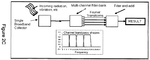
Figure 2C shows a signal detection system that uses a single broadband
collector
according to an illustrative embodiment of the invention.
Figures 2D-1, 2D-2, and 2D-3 show a signal detection system that uses a single
collector and multi-channel filter bank and the steps used in processing
incoming signals
according to an illustrative embodiment of the invention.
Figure 3A shows a conventional k-space readout in a two dimensional
rectilinear data
acquisition system.
CA 02706717 2010-05-25
WO 2009/070717 PCT/US2008/084945
Figure 3B shows a k-space readout in a two dimensional rectilinear data
acquisition
system according to an illustrative embodiment of the invention.
Figure 3C shows an intermediate image calculation stage according to an
illustrative
embodiment of the invention.
Figure 4 shows the geometry of computer simulations suitable for use in an
embodiment of the invention.
Figure 5 shows simulations for non-CRISP (left) and CRISP (right) data
processing
examples in accordance with an embodiment of the invention.
Figure 6A is a plot that shows an increase in signal amplitude as a result of
spectral
separation in accordance with an embodiment of the invention.
Figure 6B is a plot that shows the relative ratio of SNR for a multi-channel
system in
accordance with an embodiment of the invention.
Figure 6C is a plot that shows the SNR ratio of a system embodiment relative
to a
conventional system in accordance with an embodiment of the invention.
Figure 7 shows a NQR scanning system in accordance with an embodiment of the
invention.
Figure 8 shows a schematic diagram that depicts the interleaved excitation of
NQR
spectral line clusters in accordance with an embodiment of the invention.
[0037] The claimed invention will be more completely understood through the
following
detailed description, which should be read in conjunction with the attached
drawings. In this
description, like numbers refer to similar elements within various embodiments
of the present
invention.
DETAILED DESCRIPTION
[0038] The following description refers to the accompanying drawings that
illustrate certain
embodiments of the present invention. Other embodiments are possible and
modifications
may be made to the embodiments without departing from the spirit and scope of
the
invention. Therefore, the following detailed description is not meant to limit
the present
invention. Rather, the scope of the present invention is defined by the
appended claims.
[0039] It should be understood that the order of the steps of the methods of
the invention is
immaterial so long as the invention remains operable. Moreover, two or more
steps may be
11
CA 02706717 2010-05-25
WO 2009/070717 PCT/US2008/084945
conducted simultaneously or in a different order than recited herein unless
otherwise
specified.
[0040] In general, the aspects and embodiments of the present invention
describe methods,
apparatus, and systems for significantly improving SNR for a wave-based data
acquisition
system. In various known interpolation based and other known algorithmic
solutions, the
gains in SNR are calculated in terms of incremental percentages (e.g. 5%-10%).
Signal
averaging may increase SNR on this order; for example, averaging a noisy
signal twice
improves the SNR by approximately 41% at a cost of a factor of 2 in
integration time.
[0041] In contrast, the improvement gains made possible using the devices and
methods
described herein allow SNR improvement gains that are in terms of factors (5
times better, 10
times better, etc.) at no additional cost in integration time. As such,
specific implementations
of the noise reduction technology of the present invention into various
exemplary wave-based
scanning technologies using Nuclear Magnetic Resonance (NMR) or Nuclear
Quadrupole
Resonance (NQR) will substantially increase SNR.
[0042] To achieve these increases in SNR, the present invention specifically
(1) reduces a
type of noise, which is referred to as a type of cross-frequency noise, by
signal separation,
and by this signal separation, (2) also prolong the oscillation of signal
above a noise floor,
improving SNR by increased random noise averaging and digitization noise
averaging.
[0043] The detailed description of the present invention is described in three
sections.
However, the arrangement of sections is not intended to limit the scope of the
invention in
any way. Initially, a detailed description of the origin of cross-frequency
noise and a detailed
description of the present invention for reducing cross-frequency noise is
provided. The
secondary effect of noise reduction described above is also described. Next, a
detailed
description of the present invention as applied to exemplary wave-based
scanning
technologies such as those based on NMR and NQR follows. Finally, a detailed
description
of applications of the present invention is then provided.
Section One: Cross-Frequency Noise Reduction System
[0044] The general origin of cross-frequency noise is presented in this
section. Cross-
frequency noise occurs in the common situation where a single broadband signal
is collected,
received (mixed, filtered, digitally sampled), reconstructed using a
mathematical transform
such as an FT or IFT, and then displayed or stored as an image or signal
profile. A general
12
CA 02706717 2010-05-25
WO 2009/070717 PCT/US2008/084945
multi-channel CRISP system for reducing cross-frequency noise is described for
creation of
images and/or image/signal profiles.
Origin of Cross-Frequency Noise
[0045] Signal Collection: Consider a signal collector which collects a
discrete time series
data set, Xtotal, consisting of a broad range of frequencies. The collected
signal, Xtotaz, is
almost always an electrical signal, but can also be a mechanical signal.
[0046] Receiver/Detector: In the signal receiver/detector, the collected
signal Xtotaz
undergoes three processes. First, it is mixed to a lower base frequency.
Second, the result is
put through a bandpass filter (sampling filter). The order of mixing and
filtration may be
reversed in some embodiments. Third, the mixed and filtered signal then
undergoes analog-
to-digital conversion (digital sampling). Analog-to-digital conversion is
performed at a
sampling rate at least equal to the Nyquist-Shannon sampling rate limit based
on the sampling
filter bandwidth. The time series data, Xtotaz, consists of the sum of an
underlying signal,
Stotai, and a total noise Ntotal (i.e. Xtotaz = Stotaz+ Ntotal), where Stotaz
is the total signal, and where
Ntotaz is the total noise.
[0047] Transformation: The desired result is given by a mathematical transform
of the
sampled signal, typically a Fourier Transform (FT) or Inverse Fourier
Transform (IFT).
After sampling, an FT/IFT is typically performed on the sampled time series
data, using an
FFT algorithm to create the frequency series result, Ytotal= Each calculated
data point in the
frequency series result, Ytotaz is an amplitude and phase representation of
the corresponding
frequency component of the original time series data, Xtotaz.
[0048] In one embodiment, the total detected noise, Ntotaz, of the original
time series data,
Xtotaz, which includes noise from all frequency components of the collected
signal, contributes
to every calculated value in the frequency series result, Ytotaz. The final
reconstructed data
has noise contributions from all frequency components, rather than having
noise
contributions only from the corresponding frequency component that the data
point is meant
to represent. In one embodiment, this extra noise contribution is identified
by the term
"cross-frequency noise."
[0049] An alternative explanation may be relevant to some embodiments. The
position-
dependent signal of a target may be encoded as a function of frequency as part
of a scanning
technology. Each target may be divided up into smaller targets. Each of these
smaller targets
has a signal component and an associated noise component. The noise spectrum
associated
13
CA 02706717 2010-05-25
WO 2009/070717 PCT/US2008/084945
with the smaller targets is typically much broader than the signal spectrum of
the targets
themselves. Therefore, for each of these smaller targets, some parts of their
corresponding
noise spectrum will be frequency-matched to signal (noise power where there is
signal
power) and some parts will be frequency-unmatched to signal (noise power where
there is no
signal power). In the case of the smallest target (a single voxel), all noise
contribution that
ends up beyond the bounds of the corresponding pixel in the final signal
profile is frequency-
unmatched voxel noise (alternatively, "cross-frequency noise"). All noise
contribution
contained within that corresponding pixel from that voxel can be considered
frequency-
matched voxel noise.
[0050] Various definitions of interest are as follows:
Target noise (TN) = frequency-matched TN + frequency-unmatched TN
Voxel noise (VN) = frequency-matched VN + frequency-unmatched VN (cross-
frequency noise)
[0051] Broadband detection of the entire target signal includes broadband
detection of the
signal and noise spectra from all these smaller targets. In this case, the
frequency-unmatched
noise from each voxel will overlap with the frequencies of signal from other
voxels such that
the noise is inseparable on detection.
Cross-Frequency Noise: Everyday Analogy
[0052] An analogy may be used from everyday life. Consider the signal
collection,
reception/detection of electronic organ music with the use of a single
microphone. When the
final digitized signal is sent to an oscilloscope, a complex real-time multi-
sinusoidal
waveform is displayed on the scope as a function of time. Alternatively, there
is another way
to view this same digitized signal, and that is by the amplitude of frequency
components.
When viewed on a high-end stereo system in real-time, a bar-graph spectral
profile of the
music may be displayed using colored light, with small narrowband frequency
components of
the music being displayed with a lighted bar. This spectral profile represents
the Fourier
Transform of the waveform seen on the oscilloscope.
[0053] Now imagine that three keys on the electronic organ keyboard are
pressed and that
each key has a frequency corresponding to a distinct bar on the bar-graph
spectral profile on
the stereo system. In one embodiment, each key has a signal that is equivalent
to a pure
sinusoid at a corresponding frequency. Associated with each of these signals
is a noise
component specific to the key that is pressed. This noise component has many
frequencies
14
CA 02706717 2010-05-25
WO 2009/070717 PCT/US2008/084945
including the frequency associated with the key. The single microphone
receives signal and
noise from all three keys as a single waveform. That is, the noise
contribution from all three
keys is received by the microphone all together, rather than individually. A
review of the
bar-graph spectral profile on the stereo system, three bars will be raised,
each signal of which
will have noise that is contributed from all three keys. From visual
inspection, this is due to
the use of a single microphone for reception. The noise contributed to each
bar on the bar-
graph spectral profile that is contributed by non-related organ keys is cross-
frequency noise.
Embodiments and Aspects of the Invention (CRISP)
Method of SNR Increase by Cross-Frequency Noise Reduction: CRISP
[0054] It is important to understand that by recognizing the presence and the
origin of
cross-frequency noise, systems to specifically reduce cross-frequency noise
may then be
developed. It is a common assumption that target noise cannot be reduced as
part of any
wave-based scanning technology. Contrary to this, this invention describes
methods for
increasing SNR in images by deliberately reducing the effect of the dominant
part of target
noise (or cross-frequency noise) in final images.
[0055] Signal detection by division of the target signal, with judicious
attention to
frequency-unmatched target noise, will reduce the overall amount of cross-
frequency noise in
a transformed data set. That is, if the signal from the smaller targets can be
isolated along
with only its frequency-matched TN, i.e. the frequency-unmatched TN is
eliminated, a
substantial noise reduction may occur proportional to the target division.
Further reduction in
cross-frequency noise may be made by increasing target division. A limit in
SNR
improvement is reached as the target signal per division is decreased relative
to the noise
floor, which is due to relevant frequency-matched target noise, as well as
noise related to
detection such as coil noise and digitization noise. Data recombination into a
final target
signal profile or image must be performed so that frequency-unmatched TN is
not re-
introduced.
[0056] Put another way, the key to cross-frequency noise reduction is the
excitation and/or
reception of signal from separate sub-parts of the target into separate
narrowband data
channels. This can be performed by (1) focused signal excitation of various
portions of the
target, e.g. narrowband signal excitation, followed by signal reception,
and/or (2) focused
signal reception from various sub-parts of the target. Signal and noise from
target sub-parts
can be deliberately separated from other target sub- portions, permitting the
deliberate
CA 02706717 2010-05-25
WO 2009/070717 PCT/US2008/084945
calculation of Fourier data products (i.e. signal profiles or images) with
reduced cross-
frequency noise.
[0057] In one embodiment, the invention relates to systems and methods called
Calculated
Readout by Spectral Parallelism (CRISP) which reduces cross-frequency noise,
requiring
both hardware and software components. As shown in Figure 1, in one
embodiment, the
systems and methods incorporate some or all of the following steps:
1. Narrowband channel formation (excitation and/or reception)
2 Channel-specific data sampling
3. Channel-specific data reconstruction
4. Recombination of the data from each channel into a final reconstructed data
set to
create an image or image/signal profile
[0058] The purpose of a CRISP system is to create an image or signal profile
with
markedly reduced cross-frequency noise. The effects of this noise-reduction
system are more
pronounced in situations where target noise dominates the final image noise.
For reference, a
flowchart of the CRISP process is shown in Figure 1. In addition, a
conventional broadband
reception and detection process is shown in Figures 2A-1 and 2A-2. Embodiments
based on
the CRISP and other methods of implementation according to the invention are
shown in
Figures 2B, 2C, 2D-1, 2D-2, and 2D-3.
Additional SNR Increase by Spectral Separation
[0059] An important, added, concomitant benefit of spectral separation into
narrowband
data channels is the separation of higher frequency components away from lower
frequency
components in the received signal. The aggregate of these frequency components
may cause
signal to decay quickly. Conversely, the separation of these components
lengthens the time
of signal decay in each data channel so that there is an increased time period
to sample data
prior to reaching the noise floor. This added time for sampling increases SNR
especially for
the following three cases:
(1) signal that typically decays quickly,
(2) targets with inherently low signal, and
(3) signal profiles with high spatial frequency components.
16
CA 02706717 2010-05-25
WO 2009/070717 PCT/US2008/084945
[0060] This is due to the effect of averaging two types of noise: random noise
and
digitization noise. This latter effect would be more pronounced for low signal
circumstances
where digitization noise would be prominent relative to the actual signal. As
a result, this
effect would be noticeable, for example, in improving the SNR in collected
data regarding
higher-spatial frequency components of the resulting transformed Fourier
signal profile or for
targets with inherently low signal. Specific details relating to the benefits
of spectral
separation are shown in Figures 6A-6C.
[0061] For example, in Figure 6A, the presence of increased signal amplitude
effects due to
spectral separation associated with a given embodiment are shown.
Specifically, the plot
shows the increase in signal amplitude of free-induction-decay (FID) signal
due to the slower
signal decay (1D section of 2D image) associated with a given system or method
embodiment. The uppermost waveform is the original un-filtered signal. The
bottom two
FIDs show the signal from the first and last channels of a simulated 10
channel CRISP
system. The different frequency center of the two channels is visible and both
show a
significant signal increase in signal amplitude over the unfiltered signal.
[0062] This feature of the methods and system described herein allows for
longer sampling
times as a result of the slower decay time. In turn, this results in an
improved SNR ratio for
numerous cases such as when capturing signals that decay quickly, e.g. high
T2* species in
MRI. The methods and device described herein also result in an improved SNR
ratio when
capturing signals that do not necessarily decay quickly, but are relatively
low compared to the
noise floor such as faint objects. The SNR improvement is also present when
capturing
signals that are relatively low due to the image features of the corresponding
image (Fourier
Transform) such as when the high spatial frequency components are relatively
low in signal
due to image features and would therefore benefit.
Multi-Channel CRISP:
Step 1: Narrowband Channel Formation (Excitation and/or Reception)
[0063] A multi-channel CRISP system reduces cross-frequency noise by using
multiple
separate narrowband data channels (excitation and/or reception). Separately
reconstructed
data from these data channels is recombined to calculate an image or signal
profile. The
spectral coverage of all the narrowband data channels is equivalent to the
spectral coverage of
the original broadband data so that no information is lost. The goal is to
isolate frequency-
17
CA 02706717 2010-05-25
WO 2009/070717 PCT/US2008/084945
matched noise spectra away from frequency-unmatched noise spectra to reduce
overall cross-
frequency noise.
[0064] In one embodiment, the front end of the multi-channel CRISP system is
analog and
that the back-end of the multi-channel CRISP system is digital. From the
signal and noise
that is collected from each target sub-part, only the signal and frequency-
matched noise is
desired for later data recombination. Frequency-unmatched noise (cross-
frequency noise)
can be diminished, e.g. zeroed, easily in digital mode prior to data
recombination.
[0065] In the case of multi-channel CRISP, one of two front-end
implementations can be
made. Specifically, (1), narrowband components of the single analog signal are
directly and
separately received into data channels prior to digital sampling, also
separately performed in
each data channel, e.g. multiple detection coils, and (2) a single analog
signal may be
collected first, e.g. by a single detection coil, received into a filter-bank
front-end to multiple,
separate, analog, narrowband data channels, and then digitally sampled in each
channel
separately.
(1) Direct Narrowband Signal Collection, Reception, and Filtration
[0066] Multiple narrowband signal collectors, each tuned to a different
narrowband range
of frequencies may directly receive a single broadband signal after broadband
excitation, or
receive multiple narrowband signals excited at different times or in variable
combinations.
The output of each narrowband signal collector goes to a separate receiver or
multiplexed
signal receiver. For each data channel, both mixing and narrowband filtration
occur.
Nominally, the bandpass profile of each narrowband CRISP data channel would be
identical
except for frequency ranges. Modification of the characteristics of each
narrowband receiver
can be made, however, similar to the frequency filter-bank case below, whereby
the shape,
center frequency, and width of the frequency profiles of each CRISP data
channel can be
changed according to input signal characteristics.
[0067] Additional SNR benefit due to spectral separation is obtained as
outlined earlier.
Further benefit from spectral separation may be obtained on top of this by
sending signal
from each of these narrowband CRISP data channels into a corresponding
frequency filter-
bank.
(2) Indirect Narrowband Signal Collection, Reception, and Filtration
18
CA 02706717 2010-05-25
WO 2009/070717 PCT/US2008/084945
[0068] In this method, a single broadband signal collector is attached to a
frequency filter-
bank. Narrowband excitation or coded broadband excitation can be used in
combination with
this system to reduce cross-frequency noise.
[0069] For example, a single broadband signal collector may receive multiple
narrowband
signals excited at different times or in variable combinations. A single
analog signal is
collected, mixed, and then sent into a frequency filter-bank, which acts as
the front-end to
multiple narrowband CRISP data channels. Alternatively, mixing occurs in each
data
channel separately after filtration.
[0070] For example, separate narrowband excitation with corresponding
narrowband signal
reception through the broadband signal collector and frequency-filter-bank
would allow
reduction of cross-frequency noise.
[0071] Alternatively, the magnitude and strength of asserted readout gradients
will cause
variable mapped positional shift of cross-frequency noise relative to voxel of
origin.
Broadband excitation with coded readout gradient strengths and magnitudes can
be used with
a frequency filter-bank to capture signal that can then be decoded for reduced
cross-
frequency noise. As in the first method, the use of narrowband reception will
also cause
spectral separation, permitting the advantages of increased SNR described
earlier for spectral
separation.
Aspects of CRISP Narrowband Filters
[0072] The frequency profile of each narrowband CRISP data channel is
adjustable by
changing filter profiles of the corresponding filters to each data channel.
Nominally, this
frequency profile is identical for each narrowband data channel and would be
an ideal
rectangular function in frequency, variable only in center frequency for each
narrowband data
channel. If general characteristics of the input broadband signal are known,
however, it may
be desirable to vary the shape, center frequency, and width of the frequency
profiles of each
CRISP data channel. Consider the case of a filter-bank with channels
configured to be true
square-wave spectral bandpasses that are perfectly juxtaposed. This situation
is perfectly
matched to the situation where the incoming spectral power distribution is
flat. Any
broadening of the channel filters will cause an increase in the number of
admitted Fourier
components, which will decrease the efficacy of SNR improvement by the multi-
channel
CRISP system (both by reducing cross-frequency noise and by reducing signal
separation
effects).
19
CA 02706717 2010-05-25
WO 2009/070717 PCT/US2008/084945
[0073] More realistically, the incoming distribution of spectral power is not
completely flat,
but is distributed according to a pattern dictated by the image signal
intensity distribution and
the strategy for encoding the radiation from the affected volume. For a given
spectral power
distribution, the sequence of filter bandpasses can be configured to produce
optimal SNR in
the Fourier domain or Inverse Fourier Domain. For example, if the final image
is of a
discrete object, the Fourier description of that object has most of the energy
located in the
lower order spatial frequencies. If, as is the case in MRI, the Fourier
Transform is the actual
signal that is collected, then it may be more judicious to divide lower order
acquired data into
more narrowband data channels than higher order acquired data, in order to
more optimally
remove cross-frequency noise contributions. Balancing this, in order to
improve the effects
of spectral separation, which benefits higher order acquired data more than
lower order
acquired data, it may be judicious to divide higher order acquired data into
more narrowband
channels than lower order acquired data. Optimal solutions may be reached
based on this
balance.
Step 2: Channel-Specific Data Sampling
[0074] Data sampling involves the conversion of an analog signal to a digital
signal. Data
sampling involves the use of A/D converter(s), which are well known in the
art, and in the
usual case of analog electronic to digital electronic signal conversion, take
an analog
electronic signal as input and provide a digitized electronic signal as
output.
[0075] Within a multi-channel CRISP system, analog signals are digitally
sampled within
each CRISP data channel, separate from sampling in other CRISP data channels.
This data
sampling is performed using A/D converter(s), with either one channel per A/D
converter, or
multiplexed so that more than one channel shares an A/D converter. The minimum
sampling
rate requirements for each CRISP data channel will be dependent on that CRISP
data
channel's particular narrow bandwidth, and not on the overall broadband
frequency range.
[0076] There is an effect introduced to the detected signal by the A/D
converter which
results in a type of noise called digitization noise. In cases where signal is
low, this
digitization noise can be an important noise source. Spectral separation, as
is the case in
CRISP, causes prolonged duration of signal above the noise floor. In cases of
inherently low
signal, the effect of this digitization noise is reduced. This effect would be
noticeable in
improving the SNR in collected data regarding higher-spatial frequency
components of the
resulting transformed Fourier signal profile or for targets with inherently
low signal.
CA 02706717 2010-05-25
WO 2009/070717 PCT/US2008/084945
[0077] A specific example of this effect is described with respect to Figure
6B. As shown
in Figure 6B, by using the systems and methods described herein digitization
noise is
reduced. The plot of Figure 6B shows the relative ratio of SNR of a 10 channel
embodiment
of the invention relative to a conventional non-CRISP system (vertical axis)
as a function of
the number of bits used to digitize the signal (horizontal axis). This
provides a measure of
digitization noise and digitization noise improvement by CRISP. At a small
number of
digitization bits (<5), the improvement is relatively small but it quickly
increases to a lOx
factor and stabilizes at that level.
[0078] In addition, as shown in Figure 6C, the plot shows the SNR ratio of a
system
implementing the techniques and devices described herein relative to a non-
CRISP system
(vertical axis) with a varying number of CRISP channels in the case of
digitization-noise
limited signal. From the figure, it is clear that the SNR improvement scales
linearly with the
number of channels in the CRISP system.
[0079] Typically, when a band-limited signal is sampled, the Nyquist-Shannon
Theorem
requires a sampling interval smaller than two per bandwidth. In the case where
no a priori
information exists regarding the frequency range spanned by the data, the
restricted Nyquist-
Shannon Theorem requires sampling intervals smaller than two per highest
frequency. For
instance, a signal would need to be sampled at a minimum sampling frequency of
2 - B in
order to maintain full signal information for signals with frequencies from 0
through B. In
standard practice in the real world, signals are often filtered to maximum
frequency B prior to
sampling at a frequency of 2 , B to prevent undesirable signal above maximum
frequency B
from aliasing into the sampled data.
[0080] It is important to note that if the signal to be sampled is band-
limited, the minimum
sampling frequency, as indicated by the Nyquist-Shannon Theorem, is not 2 , B.
Consider a
broadband signal with bandwidth Af. Using the Nyquist-Shannon Theorem, the
minimal
sampling rate is frequency 2, Af.
[0081] In a multi-channel CRISP system, however, multiple, separate,
narrowband data (N
channels) are created either by multi-channel narrowband filtration of the
broadband signal or
direct detection of narrowband signal. Each set of narrowband data has a
narrow bandwidth
3f, and the corresponding minimal sampling rate by the Nyquist-Shannon Theorem
to avoid
aliasing is 2 - 6f = 2 - Af IN. That is, complete preservation of narrowband
information can be
maintained by a minimal sampling rate of 2 - Af IN.
21
CA 02706717 2010-05-25
WO 2009/070717 PCT/US2008/084945
[0082] Thus, an important and interesting feature of a multi-channel CRISP
system is that it
has a relaxed minimum sampling rate requirement by a factor N compared to the
nominal
Nyquist-Shannon sampling rate. This means that significantly less data needs
to be collected
in each data channel per unit of time to satisfy Nyquist-Shannon sampling rate
requirements,
significantly reducing nominal acquisition time. The savings in time may be
further used to
increase SNR by taking further data.
[0083] It is also important to note that it is possible that the narrowband
CRISP data
channels will have different bandwidths, as outlined earlier. In this case,
the minimum
sampling rate requirements for each channel may vary. While it can be
efficient to choose a
single sampling rate that would comply with the most stringent of these
requirements, it may
sometimes be more efficacious instead to permit variability in sampling rates
between
channels.
Step 3: Channel-Specific Data Reconstruction
[0084] Within a multi-channel CRISP system, data is reconstructed or
transformed within
each data channel without information from other data channels. This isolates
each data
channel from each other, and prevents cross-frequency noise contribution
between data
channels.
[0085] Nominally, the main reconstruction algorithm is an FT or IFT, and would
be
preferentially performed directly without using the FFT algorithm, as the FFT
imposes no a
priori constraints on the frequency distribution of the input signal. If the
signal is known to
be band-limited, as in the case with CRISP, a more complex algorithm such as a
Bayesian
technique can be employed to more optimally perform the FT or IFT. With a
multi-channel
CRISP system with large N (number of narrowband channels), the number of
frequencies
within each channel is very small. In this case, a direct FT or direct IFT of
the data may be
more computationally inexpensive than the FFT method. In the maximal multi-
channel
CRISP system called SUPER-CRISP, also described later in the MRI section, only
a single
spectral component is present, and any method of spectral inversion will be
able to solve for
the intensity of the single detected sinusoid per channel with high accuracy.
Specifically,
with SUPER-CRISP, only a few measurements per channel would be needed. In this
case,
the method of transformation becomes significantly less relevant. Data
reconstruction may
be performed by software (computer program) or hardware (dedicated digital
signal
processing circuits).
22
CA 02706717 2010-05-25
WO 2009/070717 PCT/US2008/084945
Step 4: Data Recombination into an Image or Signal Profile
[0086] Recombination of all of the reconstructed data is then performed at the
end. This
may be a delayed recombination depending on what type of signal excitation
(broadband or
narrowband) technique was used. Regardless, collection of all required data
would be
finished at some point.
[0087] The manner of the recombination would depend upon the type of
transformation/reconstruction that was used. Nominally, if FT/IFT were used
for
transformation, simple summation or concatenation of data can be performed.
Since FT/IFT
data reconstruction encodes position to frequency and vice versa, the output
of narrowband
CRISP data channels may be concatenated according to the specific narrowband
frequency
ranges involved. This operation may also be considered a summation, if one
assumes that
most of the data output would be zero except for data points that correspond
to each
particular narrowband CRISP data channel. The result is an image or signal
profile. This
step may also be implemented either in software or in hardware.
Certainly, in the simplest case, all (or a subset thereof) frequency-unmatched
noise
regions in the data from each narrowband CRISP data channel may be zeroed
prior to data
recombination. In circumstances where there may be a weighted noise effect so
that noise
may be associated with a weighted amount of signal at each frequency, then an
appropriate
weighting of the noise rather than a zeroing is performed in one embodiment,
followed by
summation.
Multi-Channel CRISP: Gain in SNR by Reducing Cross-Frequency Noise
[0088] Within a multi-channel CRISP system, by separating the input signal
into multiple
narrowband data channels that are reconstructed separately, cross-frequency
noise between
narrowband data channels is reduced nominally to zero. Increasing the number
of
narrowband data channels has a commensurate effect in reducing cross-frequency
noise.
Maximum reduction of cross-frequency noise occurs when the number of channels
is
equivalent to the number of pixel elements in the reconstructed image or
signal profile
(SUPER-CRISP).
[0089] A multi-channel CRISP system, therefore, greatly improves SNR in the
final
reconstructed (e.g. Fourier transformed) data, without additional acquisition
time. For
example, consider an input signal with total bandwidth Af and a CRISP system
with N data
channels, each with narrow bandwidth 8f (where Af = N - 8f). Cross-frequency
noise is not
23
CA 02706717 2010-05-25
WO 2009/070717 PCT/US2008/084945
the only source of noise within any system, but if the noise in the detection
process depends
on the bandwidth (as is the case with many systems), the integration time
required by the
CRISP system to achieve a given image SNR is a factor ' less than in the
conventional case,
where x=1 in the case where the noise scales linearly with the bandwidth, and
x=O where the
noise is independent of bandwidth. In the former case, full benefit is
achieved with the
CRISP method over conventional methods, and in the latter case, no benefit is
achieved. In
the latter case, the noise power scales as (bandwidth, and so a SNR gain of
'IN is achieved by
filtering out the cross-frequency noise. In other words, the noise on the
detector decreased
when the bandwidth in decreased, and so a smaller amount of noise is applied
to a smaller
range of frequencies.
[0090] In the case where cross-frequency noise dominates other noise in the
final
reconstruction, the expected improvement in SNR using a multi-channel CRISP
system with
N narrowband data channels would be close to IN. A 64-channel CRISP system
would have
a maximum SNR improvement of a factor of 8. Similarly, a 256-channel CRISP
system
would have a maximum SNR improvement of a factor of 16.
Multi-Channel CRISP: Gain in SNR by Spectral Separation Effects
[0091] As mentioned earlier, an important added benefit of spectral separation
into
narrowband data channels is the lengthening of the time of signal decay in
each data channel
so that there is an increased time period to sample data prior to reaching the
noise floor. This
added time for sampling increases signal-to-noise (SNR) especially for (1)
signal that
typically decays quickly, (2) targets with inherently low signal, and (3)
signal profiles with
high spatial frequency components. This is due to the effect of averaging two
types of noise:
random noise and digitization noise. This latter effect would be more
pronounced for low
signal circumstances where digitization noise would be prominent relative to
the actual
signal.
[0092] With increased spectral separation, digitization noise in the image
decreases
linearly. Accordingly, if the noise in an image is dominated by the
digitization noise, it is
possible to see a SNR increase equal to the number of narrowband channels. A
CRISP
system with 16 channels would see a 16-fold increase in the output image SNR
in that
circumstance.
Multi-Channel CRISP in Single Channel Mode
24
CA 02706717 2010-05-25
WO 2009/070717 PCT/US2008/084945
[0093] A multi-channel CRISP system can be used to collect data serially from
small areas
of the target with only one or a few channels being used at any one time.
Ideally, narrowband
signal is excited so that it corresponds to a narrowband CRISP data channel,
such that
received data passes efficiently through that particular channel. Narrowband
excitation
ensures that sub-parts of the target signal are received at any one time, so
that frequency-
matched signal and noise may be received without cross-frequency noise from
other sub-parts
of the target.
[0094] In this mode, the CRISP benefits of increasing SNR by the two effects
of reducing
cross-frequency noise and by spectral separation effects are still maintained.
Numerous
combinations of narrowband signal excitation (and reception) may be obtained.
[0095] For example, narrowband signal excitation may be performed sequentially
so that
adjacent strips of tissue can be excited in a serial manner or excited in an
interleaved fashion
to avoid cross-talk of signal excitation.
Single Channel CRISP
[0096] Alternatively, a single-channel CRISP system can be made. In this case,
the single
channel in single-channel CRISP is identical to any of the channels in multi-
channel CRISP
with the exception of center frequency. This center frequency may itself be
adjusted during
imaging or instead, incoming signal may be appropriately mixed to a fixed
center frequency
for the channel.
[0097] As in the case of multi-channel CRISP in single channel mode, strict
attention to
data acquisition, data reconstruction, and data recombination must be
performed so that
cross-frequency noise is deliberately and consistently reduced. An additional
effect of
spectral separation will be had by the use of a single narrowband system.
Section Two: Introduction to Exemplary Wave-Based Data Acquisition Systems
Conventional MRI/MRS
[0098] In the fields of MRI, MRS, and MRSI, all based on NMR, certain nuclei
with a net
magnetic moment are placed within relatively homogeneous applied magnetic
fields and are
disturbed from thermodynamic equilibrium using electromagnetic waves at the
Larmor
frequencies of the nuclei (typically at radio frequencies (RF)). As relaxation
occurs back to
thermodynamic equilibrium, there is emission of RF waves at the same Larmor
frequencies.
These RF waves are detected using RF antenna(e) or coils, sampled, and stored.
An Inverse
CA 02706717 2010-05-25
WO 2009/070717 PCT/US2008/084945
Fourier Transform (IFT) is performed on the sampled data to provide a final
image (in the
case of MRI) or signal profile (in the case of MRS).
[0099] In MRI, data is collected during the assertion of a linear magnetic
gradient or
combination of linear magnetic gradients to achieve spatial localization of RF
signal. Data
that is collected in this manner represents data collection and traversal in
the state-space of
the spin system in MRI; this state-space is also called k-space, and
represents the Fourier
Transform of the final MRI image(s). In the nominal case, rectilinear
collection of data in k-
space is performed with each line in k-space acquired after a single RF
excitation. In the case
of standard echo-planar imaging (EPI), an entire rectilinear data set in k-
space is collected
after a single RF excitation. Non-rectilinear data collection pathways may
also be used,
including projection reconstruction imaging (which acquires data in linear
radial arms from
the k-space center), and spiral imaging (which acquires data in spiral arms
from the k-space
center), among others. Many different k-space trajectories may be used and
have been
described. In all cases in MRI, data is collected during the assertion of a
linear magnetic
gradient or combination of linear magnetic gradients.
[0100] In MRI, as a result, acquired data consists of a broadband of free
induction decay
(FID) signals at numerous varying Larmor frequencies associated with the local
magnetic
environment of the nuclei that are being imaged, and the combination of the
applied main
magnetic field and the superimposed magnetic fields of asserted linear
magnetic gradients.
[0101] In MRS, data is not collected during the assertion of a linear magnetic
gradient, but
due to the higher frequency resolution requirements, acquired data also
consists of a
relatively broadband of FID signals at varying Larmor frequencies associated
with the local
magnetic environment of the nuclei that are being imaged and the applied main
magnetic
field. These kinds of signals are also present under MRI conditions, but are
less spectrally
resolved due to technical factors.
[0102] MRSI may be considered a combination of MRI and MRS, whereby data is
collected during the assertion of a linear magnetic gradient, and also divided
further by the
high spectral resolution of signal within each pixel. For the purposes of
brevity, application
to MRSI is assumed if an application to MRI or MRS is described in this
present document.
[0103] In the case of MRI and MRS, after data collection, an Inverse Fourier
Transform
(IFT) is performed, invariably using a Fast Fourier Transform (FFT) algorithm.
The FFT
algorithm is a very common technique used in many fields and applications that
efficiently
26
CA 02706717 2010-05-25
WO 2009/070717 PCT/US2008/084945
calculates a Fourier Transform or Inverse Fourier Transform of a 2M data
length in time M
log(M) rather than M2. In the case of MRI, an image representation of the
signal amplitude
and signal phase relative to position is obtained by the IFT, whereas in the
case of MRS, a
profile of signal amplitude and signal phase relative to frequency offset from
the center
Larmor frequency is obtained.
[0104] Specifically, in MRI, it is now common to use parallel data acquisition
and
reconstruction in the phase encoding direction, primarily during rectilinear k-
space data
acquisition, under the general term "parallel MRI". Many such techniques have
been
described in the field using names such as SENSE, SMASH, PILS, GRAPPA, SPACE-
RIP,
SEA, among others. Such techniques consist of using multiple spatially
targeted RF coils,
each with limited spatial coverage. The sensitivity of each coil can be
determined, and
contributions of MR signal from other regions of the body other than from each
coil itself can
be eliminated mathematically. Since data is being received in parallel from
these different
targeted regions, a reduced number of phase encoding steps may be performed
resulting in a
shorter overall scan time. In this circumstance, there is also an associated
reduction in signal-
to-noise ratio (SNR) using parallel MRI. Alternatively, a high number of phase
encoding
steps may be retained, resulting in a high spatial resolution scan with large
field of view
(FOV) coverage for the same scan time, albeit with an attendant small
parasitic SNR loss
compared to a nominal non-parallel MRI scan.
Cross-Frequency Noise in Conventional MR IMRS
[0105] Signal Collection: Each MRI and MRS signal is composed of many
different
frequency components, and can be considered a broadband signal for the
purposes of
description in this document. In MRI, the signal is received during the
assertion(s) of linear
magnetic gradients during what is known as the readout. In MRS, a higher
frequency
resolution examination is performed on the signal without the use of imposed
linear magnetic
gradients, eliciting differences in resonance frequencies due to specific
physical chemistries
of molecules; acquisition of the spectral data can also be considered the
equivalent of the
readout in MRI.
[0106] Signal collection is performed with the use of a tuned RF coil. The
collected RF
waves are thus converted into an electrical signal in the coil output. In the
case of either MRI
or MRS, each frequency component i can be considered a sinusoidal signal Si
with its own
associated noise component Ni. The combination of all frequency components (Si
and N) and
27
CA 02706717 2010-05-25
WO 2009/070717 PCT/US2008/084945
the addition of other sources of noise comprise the single broadband input
waveform Xtotai
that comes from MRUMRS RF coils for sampling. Conversely, the single input
waveform
Xtotaz is the sum of a total signal Stotaz and a total noise Ntotal (i.e.
Xtotaz = Stotaz+ Ntotaz), where
Stotaz is the sum of all MRI or MRS signal that the RF coil(s) receive, and
where Ntotaz is the
total noise, comprised of the noise of all frequency components, coil noise,
as well as
electronic noise.
[0107] Receiver/Detector: After signal collection, the electrical input
waveform is sent to a
receiver for mixing, filtration, and sampling. Data sampling is performed by
analog-to-
digital conversion at a sampling rate at least equal to the Nyquist-Shannon
sampling rate
limit.
[0108] Transformation: In conventional MRI or MRS, an IFT is performed on the
received
single input waveform using an FFT algorithm to create waveform Ytotaz.
Ignoring relaxation
effects, each calculated data point in the IFT-FFT waveform Ytotaz is an
amplitude and phase
representation of the corresponding frequency component of single input
waveform Xtotaz.
[0109] Noise: An important feature of this conventional for MRI and MRS is
that the total
noise Ntotaz of the single input waveform Xtotaz, contributes to every
calculated data point of
Ytotaz. Therefore, each data point in the final reconstructed image or signal
profile data has
significant cross-frequency noise contributions.
[0110] Put another way, for each voxel, the sample signal is at a signal
position of the
transformed data, but the noise from that sample contributes to every point in
the transformed
data space in addition to the signal position. The transformed noise at the
non-signal
positions from the voxel is a type of cross-frequency noise. As mentioned
previously, once
the presence of cross-frequency noise is understood, NMR-based methods to
reduce cross-
frequency noise may then be developed such as described in the following
sections.
Multi-Channel CRISP MRI System
[0111] A description of a multi-channel multi-frequency processing method for
MRI/MRS/MRSI, such as a CRISP method, follows below. As in the general
invention
described in this document, a similar set of characteristic steps is present.
This multi-channel
CRISP MRI/MRS/MRSI system has an analog front-end consisting of (1) tuned RF
hardware, (2) a frequency filter-bank (or equivalent), or (3) a combination of
(1) and (2), in
order to create separate narrowband data channels. Data within each channel is
sampled
28
CA 02706717 2010-05-25
WO 2009/070717 PCT/US2008/084945
separately. In the digital back-end, data is then reconstructed separately,
and then
recombined into an image or image/signal profile.
[0112] This system is used in concert with broadband or narrowband signal
excitation
depending on the circumstance. Additionally, the use of various gradient
encoding schemes
may map cross-frequency noise to different locations such that the noise may
be calculated
out of collected data. That is, gradients will map specific cross-frequency
noise to different
locations relative to the source pixel location. Methods can be developed to
encode cross-
frequency noise to certain positions by the use of gradients in sequential
imaging such that
cross-frequency noise may be calculated out from affected pixels of the final
image.
Step 1: Division of Input Signal into Multiple Data Channels: Tuned RF
Hardware
[0113] In the case of tuned RF hardware, there are many embodiments. In each
case, data
from each hardware channel is sampled, then reconstructed (IFT), then re-
combined with
(e.g. added to) other data from other hardware channels, nominally by addition
(explained
later in this section). Reconstruction and recombination can be performed
using a
programmable computer and/or dedicated hardware.
[0114] Multiple coils or antennae are spatially placed so that full coverage
of the target
material is obtained by the sensitivity regions of each coil/antenna. The data
received from
each coil is separately sampled and reconstructed in separate narrowband data
channels. Data
recombination with the outputs of other data channels occurs at the end. The
location of the
coils or antennae can be arbitrary. In the case of parallel imaging, the coils
are laid out
parallel in a phase encoding direction. If the coils are laid out parallel in
the frequency
encoding direction, a form of parallel imaging in the readout direction
occurs. In the case of
radial acquisitions, radially oriented coils also create a form of parallel
imaging in the readout
direction. In all cases, coils or antennae are specifically tuned to different
spatial regions of
the target volume.
[0115] In one embodiment of the tuned RF hardware, moving coils or antennae
are used.
In yet another embodiment, low-noise detectors such as superconducting RF
coils or low-
temperature RF coils can be used in any of the embodiment scenarios described
above.
29
CA 02706717 2010-05-25
WO 2009/070717 PCT/US2008/084945
Examples of Tuned RF Hardware
[0116] In one tuned RF hardware embodiment, nested coils are overlaid on top
of each
other, with each coil tuned to a separate narrowband of RF frequencies. The
total spectral
coverage of the coils is equivalent to the desired broadband coverage of the
target tissue or
sample. The spatial coverage of each coil is the entire target tissue or
sample. This is a
flexible system that permits the readout to be oriented in many different
directions.
[0117] In another embodiment of tuned RF hardware, parallel RF antennae and/or
coils are
used in the frequency encoding direction. Each RF antennae/coil would feed
into a single
CRISP data channel. This type of physical configuration is suitable for
rectilinear MRI
acquisitions.
[0118] In another embodiment of tuned RF hardware, rotating parallel RF
antennae and/or
coils are used with constant or variable speed. Each RF antennae/coil would
feed into a
single CRISP data channel. This type of physical configuration is suitable for
radially
symmetric MRI acquisitions.
[0119] In yet another embodiment of the tuned RF hardware, concentrically
placed RF coils
are used. This type of configuration may be suitable for radially symmetric
acquisitions as
the assertion of radially symmetric linear gradients would cause each RF coil
to receive an
appropriate narrowband of RF signal. Selective blocking and unblocking of RF
coils is
necessary.
[0120] In yet another embodiment of the tuned RF hardware, radially symmetric
RF
antennae and/or coils are used. This configuration would allow narrowband
decomposition
for each RF antennae separately; the RF signal from each antenna would undergo
narrowband decomposition, such as with a frequency filter-bank. Acquisition of
signal from
a radial line of RF antennae and/or coils is obtained during the assertion of
a linear gradient
in that direction. The direction of the linear gradient rotates with time.
[0121] In yet another embodiment of the tuned RF hardware, a combination of
phase
encoding and frequency encoding direction coils and/or antennae are used such
that selective
RF excitation and reception can be performed in a grid-like fashion. This kind
of system may
be used for excitation and tracking of moving tissue, for example.
[0122] In yet another embodiment of the tuned RF hardware, a combination of
the
concentric and radially symmetric RF antennae and/or coils is used. Selective
RF excitation
CA 02706717 2010-05-25
WO 2009/070717 PCT/US2008/084945
and reception may also be performed. This kind of system could also be used
for excitation
and tracking of moving tissue, for example.
[0123] In another embodiment of the tuned RF hardware, coils undergoing
rotating
translational movement or other motion are used. In yet another embodiment of
the tuned RF
hardware, rotating antennae are used. For example, multiple parallel antennae
are aligned in
one direction. Perpendicular to this direction is the readout direction for a
rectilinear MRI k-
space acquisition. Alternatively, as the antennae rotate, the readout
direction indicated by the
antennae is the direction of gradient application in a radially symmetric k-
space acquisition.
Step 1: Division of Input Signal into Multiple Data Channels: Frequency Filter-
Bank
Hardware
[0124] In the case of a frequency filter-bank, signal from a broadband signal
collector is fed
into a frequency filter-bank or equivalent, with the output going into
multiple, separate
narrowband data channels. This can occur before or after mixing of the
collected signal to a
lower base frequency. The latter case is preferred as it does not require
mixing circuitry for
every data channel, but this does not preclude the use of the former.
[0125] Frequency filter-banks take an incoming signal and filter the signal
into multiple,
separate, narrowband signals prior to sampling. In one embodiment, the filter
bank includes
a common signal receiving bus adapted to receive a composite signal; a
plurality of isolated
output buses; and a frequency filter module. This frequency filter module
includes a plurality
of bandpass filter elements, wherein the filter elements each include an input
and an output,
each of the inputs in electrical communication with the common signal
receiving bus, each of
the outputs in electrical communication with one of the plurality of isolated
output buses, the
outputs electrically isolated from the other outputs and each of the inputs.
[0126] In the simplest case, the filters are not adjustable, and are defined
by their number,
center frequency and bandwidth. In the more ideal case, the filters that are
used are
modifiable, including shape, bandwidth, and center frequency. These filters
may be modified
digitally or by circuitry. The advantage of the frequency filter-banks
approach is that it is
compatible with many different coil and/or antennae designs. The broadband
signal from
standard RF coils is sent to a frequency filter-bank, the outputs of which
each represent
multiple, separate narrowband data channels. These outputs are then data
sampled.
[0127] The frequency filter-bank does not reduce cross-frequency noise alone
and must be
integrated with pulse sequences that do selective excitation or with variable
magnetic field
31
CA 02706717 2010-05-25
WO 2009/070717 PCT/US2008/084945
gradient fields that would change the mapped location of voxel noise relative
to signal
location in order to reduce cross-frequency noise, among some possibilities.
The frequency
filter-bank however does inherently perform spectral separation and the added
SNR effects of
spectral separation are applicable.
Step 1: Division of Input Signal into Multiple Data Channels: Combination
Tuned RF
and Filter-Bank Hardware
[0128] In another embodiment, a separate frequency filter-bank is attached to
a separate RF
coil or antenna used in MRI or MRS, as part of a multi-coil setup as described
in the tuned
RF hardware section.
[0129] In another embodiment, a separate frequency filter-bank is attached to
each of a
series of RF coils or antennae used in MRI or MRS.
[0130] In either case, the added SNR effects of spectral separation are valid
with the use of
frequency filter-banks. Additionally, if the combined coils with frequency
filter-banks are
used in concert with specific pulse sequences or gradient assertions, cross-
frequency noise
may also be reduced.
Step 2: Channel Specific Data Sampling
[0131] Data sampling is performed separately for each CRISP data channel. This
may be
performed with an A/D converter assigned to each channel or by multiplexing
more than one
channel per A/D converter.
[0132] A multi-channel CRISP system for MRI, like CRISP systems for other
applications,
can take advantage of the narrowband of frequencies within each channel to
reduce Nyquist-
Shannon sampling rate constraints. The time to collect enough data for imaging
reduces by a
factor of the number of channels N. Each channel represents a range of
frequencies that
corresponds to a certain range of locations in the imaged object. Physically,
it represents a
strip or slab of excited tissue. Thus, each data channel contains information
about the
comprising pixels (e.g. four pixels per channel) that can be determined more
quickly. This
also means that a further increase in sensitivity may be obtained for a given
acquisition time;
since the needed acquisition time is reduced, the "extra time" can be used for
taking more
data.
Step 3: Channel Specific Data Reconstruction
32
CA 02706717 2010-05-25
WO 2009/070717 PCT/US2008/084945
[0133] In a multi-channel CRISP MRUMRS system, data reconstruction is
performed
separately on the data in each CRISP data channel. Nominally, this is
performed with direct
IFT.
Step 4: Data Recombination into Image or Signal Profile
[0134] After separate data reconstruction in each CRISP data channel, the data
is
recombined. The recombination can be tied to the way that data reconstruction
is performed.
The manner of this separation transfers the data from each data channel to the
final image
without introduction of cross-frequency noise from other data channels.
[0135] In this section, the separate cases of parallel imaging in the readout
direction and
parallel imaging in the phase encoding direction using the CRISP system
specifically for
cross-frequency noise reduction with secondary spectral separation benefits
are described.
CRISP MRI in the Phase Encoding Direction
[0136] Consider a multi-channel CRISP system performing parallel imaging in
the phase
encoding direction. The purpose of the multi-channel CRISP system is to reduce
cross-
frequency noise along with receiving the other benefits of parallel imaging in
the phase
encoding direction such as decreased scan time. In this case, each narrowband
CRISP data
channel is collecting data from a parallel imaging channel. While it is
commonly understood
that parallel imaging in the phase encoding direction will cause a reduction
in SNR, the use
of a multi-channel CRISP system with parallel imaging in the phase encoding
direction will
add to the SNR by the reduction of cross-frequency noise.
[0137] Separate reconstruction of image data from each of these narrowband
CRISP data
channels must be performed in order to minimize cross-frequency noise between
channels.
Each set of image data from each CRISP data channel represents an intermediate
image that
has signal and frequency-matched noise in the appropriate spatial locations as
per standard
MRI spatial localization. The locations match the corresponding positions of
each parallel
imaging channel. All other locations will be zeroed. Performance of the
reconstruction is
best performed in a direct manner. That is, for each non-zero intermediate
image position,
the magnitude and phase are calculated with a direct IFT with the data from
the narrowband
CRISP data channel. The sum of all intermediate images would then correspond
to the final
MRI image, but with reduced cross-frequency noise between narrowband CRISP
data
channels.
33
CA 02706717 2010-05-25
WO 2009/070717 PCT/US2008/084945
[0138] This approach differs from routine non-CRISP parallel imaging in the
phase
encoding direction in that data reconstruction is separate for each data
channel and that data
recombination requires the zeroing of regions in each intermediate image that
are not related
to the corresponding narrowband CRISP data channel.
[0139] These specific actions reduce cross-frequency noise. It is can be the
case that coil
noise dominates image noise rather than sample noise, especially for low
magnetic field
strengths and for poorly designed RF coils. If these actions are ever
performed without
understanding the nature of cross-frequency noise (part of sample noise) and
its origin as part
of the imaging process, there may not be significant noise reduction enough to
warrant
further investigation. The use of a multi-channel CRISP system is directed
directly at the
reduction of cross-frequency noise in final MRI images and would have its best
effect when
cross-frequency noise dominates.
CRISP MRI in the Readout Direction
[0140] Now consider a multi-channel CRISP system performing parallel imaging
in the
readout direction. The actual readout direction is variable. For example, the
readout
direction may be radial in the case of a radial-symmetric k-space acquisition,
or may be
perpendicular to the phase encoding direction in the case of a rectilinear k-
space acquisition.
[0141] At each point in k-space, the acquired data consists of a set of phase
and amplitude
measurements as a function of each channel, or more by inference, narrowband
frequency. In
this way, the CRISP process is adding a third dimension (frequency, maximum
index N) to k-
space (defined by the phase- and frequency-encoding directions).
[0142] In one embodiment, each narrowband CRISP data channel has an output of
a
number of data points which represent points in the final image. In MRI,
position is encoded
in the readout direction by frequency of precession. Thus, the data contained
within a
narrowband CRISP data channel corresponds to corresponding adjacent object
positions.
Data recombination in the nominal case simply involves concatenation of
outputs from the
various narrowband CRISP data channels, according to their corresponding
object positions.
If a 16-channel CRISP MRI system with 256 data point readout is used, each
narrowband
CRISP data channel outputs data for 16 data points in the final image. The
operation of
recombination can be considered addition, if each narrowband CRISP data
channel can be
considered to have a 256 data point output, most of the data points of which
have zero value,
34
CA 02706717 2010-05-25
WO 2009/070717 PCT/US2008/084945
except for the 16 data points that correspond to the particular narrowband
CRISP data
channel. A more specific description of image reconstruction follows.
CRISP MRI in the Readout Direction: 1D
[0143] Standard MRS scanning outputs are essentially 1-D signal profiles.
After separate
transformation in each CRISP narrowband data channel, the data from each
channel is
recombined into a signal profile. Since position is encoded by frequency, data
recombination
involves concatenation of outputs from the narrowband CRISP data channels
according to
their corresponding positions. This action may be considered summation if non-
relevant
frequency positions are zeroed in each channel output.
CRISP MRI in the Readout Direction: 2D and beyond
[0144] To explain how CRISP NMR image creation can be performed, first
consider a
standard NMR system that would be modified for image production. The collected
data set
can be described as k-space and that the final image is the IFT of the k-space
data.
[0145] Assume the image and k-space matrices are each M x M pixels. After
collection of
an entire M x M k-space data matrix, a multi-dimensional IFT-FFT is performed
on the data
set, which is essentially equivalent to applying a 1D IFT-FFT in each spatial
dimension.
Direct calculation of the IFT could be performed, but is avoided due to
computation
requirements.
[0146] Now consider an N-channel CRISP NMR system. In the case of a standard
rectilinear k-space trajectory with standard phase (ky direction) and
frequency encoding (kx
direction), N narrowband channels of k-space data are simultaneously collected
during each
readout. After M phase encoding steps, data acquisition is complete.
Reconstruction is
performed with direct calculation of the IFT to maintain reduced cross-
frequency noise
levels. Direct IFT calculation requires understanding the relationship of the
data within each
CRISP channel to the final image. Specifically, data within each CRISP channel
represents a
vertically oriented rectangular strip of pixels measuring M/N x M pixels in
the desired image
(Figures 3A-3C). The leftmost strip would have an RFB value of 1 and the
rightmost strip
would have an RFB value of N. Figure 3A depicts the k-space pathway of a
single readout of
a standard rectilinear k-space acquisition. As shown in Figure 3A, each line
of k-space that is
collected involves a single readout channel. After acquisition of all of the
desired data in k-
space in a raster-like fashion, e.g. 256 x 256 data points, an IFT is
performed to calculate the
final image (also 256 x 256 data points).
CA 02706717 2010-05-25
WO 2009/070717 PCT/US2008/084945
[0147] In an N-channel CRISP imaging system, e.g. for MRI, the k-space pathway
for each
readout is not changed, but there are now N parallel readouts, one for each
CRISP channel as
shown in Figure 3B. Further, with respect to Figure 3B, each line of k-space
that is collected
involves multiple readout channels. If there are N channels, N complete sets
of k-space are
collected, one for each channel. This can be considered to be an added
dimension to the
acquired k-space data. After acquisition of all of the desired data in k-space
in a raster-like
fashion, an IFT is performed to calculate the final image.
[0148] The data from each CRISP channel corresponds to a rectangular strip of
image data
(Figure 3C). Since there are N channels, and each rectangular strip of image
data is M/N
pixels in the short axis, this comprises the entire image data set, if a 2D
image data set is
considered. With respect to Figure 3C, as shown an intermediate image
calculation is
performed using information from each data channel (such as a CRISP data
channel). In the
case of a raster scan, this forms a rectangular area.
[0149] There are at least two different methods to perform the direct IFT for
a rectilinear k-
space trajectory. First, the IFT value of each image pixel is directly
determined by the
Inverse Fourier contributions of data from the corresponding CRISP channel as
indicated by
the RFB value. Second, intermediate images from each of the k-space data
points in the
corresponding CRISP channel may be summed. Each intermediate image (M x M
pixels) has
zero-value pixels except for a corresponding non-zero rectangular strip (M/Nx
M pixels) with
signal values describing a single spatially distributed sinusoid. For each
rectangular strip, the
sum of all of the intermediate images for each channel directly calculates the
IFT. The sum
of all IFTs from each channel is equivalent to a concatenation of the
transformed data from
each CRISP channel (putting the rectangular strips together). With either
method, the IFTs of
each of the CRISP channels (RFB = 1 to N) is calculated while maintaining
cross-frequency
noise within each channel.
[0150] Now consider a radially symmetric k-space trajectory such for
projection
reconstruction NQR using CRISP NQR. Each readout trajectory runs linearly from
the k-
space origin to the k-space periphery. One method of reconstruction uses the
Fourier central
slice theorem. The Fourier central slice theorem indicates that the 1D IFT of
each radial line
in k-space represents a summation projection through the object in the
perpendicular
direction. Accordingly, the IFT calculation is for a 1D situation, as
described in the previous
section. The equivalent of filtered back-projection may be performed by
multiplying the k-
36
CA 02706717 2010-05-25
WO 2009/070717 PCT/US2008/084945
space data in each CRISP data channel by the appropriate filter weighting
factors (many of
which are zero) prior to back-projection in the image domain.
[0151] Another method of reconstructing projection reconstruction CRISP NMR is
to use
the intermediate image method described above for rectilinear k-space
trajectories. In this
case, the non-zero rectangular strips are located in the image perpendicular
to the direction of
the readout gradient, and at a location according to the corresponding CRISP
data channel.
The non-zero data values in each rectangular strip are calculated directly
from the k-space
data in the corresponding CRISP data channel to form an intermediate image.
The final
desired image may be created by summation of all intermediate images.
Filtration may be
performed preferentially on the k-space data by multiplication or on the final
image by
convolution.
[0152] For the general case of any k-space trajectory, N narrowband channels
of k-space
data are simultaneously collected during each readout. The intermediate image
method
described above may be generalized to any k-space trajectory by using the
instantaneous
tangent of the k-space trajectory to determine the location and rotation of
each non-zero
rectangular strip.
[0153] These concepts are not limited to two dimensions, and can be extended
easily to
multi-dimensional situations.
Multi-Channel CRISP MRI: Gain in SNR by Reducing Cross-Frequency Noise
[0154] The use of a multi-channel CRISP system with a high number of channels
in either
the phase encoding or the readout direction would substantially increase SNR
from the
nominal case. Accordingly, substantially better image quality or faster
imaging may be
obtained in MRI and greater detectability may be gained in both MRI and MRS.
[0155] Target noise (also called sample noise or patient noise) is commonly
understood to
dominate at routine clinical magnet strengths of 1.5T. In high channel
parallel imaging in the
phase encoding direction, this relation is reduced as there is a relative loss
of corresponding
signal in each channel compared to the noise floor of data acquisition. The
noise floor is
made of coil noise, electronic noise, digitization noise, and sample noise
(including cross-
frequency noise). Methods to reduce the non-sample noise sources such as
better coil design
and low noise coils such as superconducting RF coils would only increase the
dominance of
sample noise (and thus cross-frequency noise). The use of a multi-channel
CRISP system in
this case would help to significantly reduce noise.
37
CA 02706717 2010-05-25
WO 2009/070717 PCT/US2008/084945
[0156] For example, when cross-frequency noise is the dominant noise, an N-
channel
CRISP MRI system, e.g. N=256 channels, would have up to SIN or 16 times more
SNR than a
conventional MRI system. Compared to a conventional MRI system performed on a
1.5 T
magnet, this would be the equivalent of having the same SNR as from a 24 T
magnet, but
with no change in precessional frequencies or RF heat deposition constraints.
This markedly
increased SNR that a multi-channel CRISP system translates to overall higher
sensitivity for
MRS and MRI, higher spatial resolution for MRI, and faster imaging for MRI.
Multi-Channel CRISP MRI: Gain in SNR by Signal Separation
[0157] As mentioned earlier, an important added benefit of spectral separation
into
narrowband data channels is the lengthening of the time of signal decay in
each data channel
so that there is an increased time period to sample data prior to reaching the
noise floor. This
added time for sampling increases signal-to-noise (SNR) especially for (1)
signal that
typically decays quickly, (2) targets with inherently low signal, and (3)
signal profiles with
high spatial frequency components. This is due to the effect of averaging two
types of noise:
random noise and digitization noise. This latter effect would be more
pronounced for low
signal circumstances where digitization noise would be prominent relative to
the actual
signal. With increased spectral separation, digitization noise decreases
linearly.
Accordingly, if the noise in an image is dominated by the digitization noise,
it is possible to
see an SNR increase equal to the number of narrowband channels. A CRISP MRI
system
with 16 channels would see a 16-fold increase in the output MRI image SNR in
that
circumstance. Details relating to the effects of spectral separation are also
discussed above
with respect to Figures 6A-6C.
CRISP MRI in the Readout Direction: Gradient Encoding of Cross-Frequency Noise
[0158] Cross-frequency noise is the sample noise from a voxel that has
frequencies that
overlaps with the signal frequencies of other voxels. Not all of this cross-
frequency noise
would be random, and may be conditioned by certain microscopic effects
including hydration
shells around proteins, semi-solid, and solid material noise distribution
effects. As such, the
displacement of this cross-frequency noise may be affected to some degree by
the size of
readout gradients, and therefore can be manipulated relative to desired
signals so that these
non-random portions may be algebraically removed or reduced from several
acquisitions with
different gradient strengths.
38
CA 02706717 2010-05-25
WO 2009/070717 PCT/US2008/084945
[0159] For example, a certain gradient strength will displace certain cross-
frequency noise
at a certain away from a voxel's position in the image. The reverse or
negative of this
gradient strength will displace such cross-frequency noise at the same
distance from the
voxel's position in the image but in the opposite direction.
Multi-Channel CRISP MRI: Single Channel Mode
[0160] Selective excitation of tissue can be integrated into a multi-channel
CRISP MRI
system. Specifically, strips of tissue are excited with their long axis
perpendicular to the
readout direction. Either a multi-coil, multi-channel CRISP MRI system, or a
single coil,
multi-channel frequency-bank CRISP MRI system may be used with this type of
selective
excitation. The selective excitation should be performed optimally to match
the parameters
of specific narrowband CRISP data channels.
[0161] Numerous combinations of excitation of narrowband signal may be
obtained. In its
simplest form, a single strip of tissue is excited and received at a time,
using a single
narrowband CRISP data channel at a time. A nominal situation may be a pulse
sequence that
would excite bands of tissue in the readout direction in a serial pulsed
manner. The received
data would each go through a corresponding narrowband CRISP data channel, and
finally,
data reconstruction and data recombination would be performed in a manner to
reduce cross-
frequency noise. The use of narrowband data channels is enough to also create
signal
separation effects as described earlier.
Single Channel CRISP MRI
[0162] Alternatively, a single narrowband CRISP system can be made focusing on
the two
effects of increasing SNR: by reducing cross-frequency noise, and by signal
separation
effects. In this case, a single narrowband CRISP data channel using a
narrowband filter
rather than a narrowband tuned RF coil is best used.
[0163] In the nominal case, a pulse sequence would excite bands of tissue in
the readout
direction in a serial pulsed manner. The received data would each go through
the single
narrowband CRISP data channel, and each time, would either be mixed down to
the center
frequency of the data channel, or the center frequency of the data channel
would be changed
to the center frequency of the received data. Data reconstruction and data
recombination
would occur in a similar manner to other CRISP manifestations.
Multi-Channel CRISP for MRUMRS: Computer Simulation
39
CA 02706717 2010-05-25
WO 2009/070717 PCT/US2008/084945
[0164] To demonstrate the SNR gains that are possible with a multi-channel
CRISP system
for MR imaging, a computer simulation was created. The simulation has been
implemented
for the cases of a conventional non-CRISP MRI system and a multi-channel CRISP
MRI
system (128 channels).
[0165] The simulation begins with an ideal noiseless image of a human head.
From this, a
computer-base system synthesizes the corresponding k-space data by Fourier
Transform.
Noise is then added according to two different situations: conventional non-
CRISP and 128-
channel CRISP MRI. The detected k-space noise is assumed to be proportional to
the square-
root of the receiver bandwidth. An Inverse Fourier Transform is then performed
to obtain the
final images that would result from a conventional non-CRISP implementation
versus a 128-
channel CRISP MRI implementation.
[0166] The generalized path for the simulation is shown in Figures 2C and 2D-
1, and
others, for the case of a single broadband collector, and a series of
narrowband detectors each
tuned to a separate frequency. In one embodiment, the series of narrowband
detectors are
each tuned to an independent central frequency. From the standpoint of the
simulation, both
situations are equivalent and result in identical simulated images. The
specific geometry of
this situation is shown in Figure 4. The following method was used:
1. Start with a 2-dimensional, model (i.e. noiseless) image brightness
distribution,
I.(x;,y), consisting of a single slice of biological material. Here, x;,yj are
the image
coordinates.
2. Compute the Fourier transform of the model image, resulting in the model
(i.e.
noiseless) k-space complex data, I'm(kxp, kyq) for the non-CRISP case, and
I'm(kxp, kyq, fk)
for the CRISP implementation. Here, kxp and kyq are the k-space coordinates,
and fk is the
frequency of the kth channel.
3. Synthesize the detected k-space data, I'd(kxp, kyq) or I'd(kxp, kyq, fk)
for the non-
CRISP and CRISP cases, respectively, by adding noise proportional to the
detector
bandwidth to the model k-space data.
4. Compute the inverse Fourier transform of the synthesized k-space data to
reconstruct
the synthesized image data, Id(x,,y).
[0167] The results from this simulation comparing a conventional MRI system
and an N =
128 channel CRISP MRI system are demonstrated in Figure 5. In both cases, the
magnetic
CA 02706717 2010-05-25
WO 2009/070717 PCT/US2008/084945
field strength, scan time, and object signal are the same - the only
difference being whether
CRISP has been implemented or not.
[0168] From visual inspection, it is clear that the image SNR in Figure 5
(right side) has
been significantly improved. Analysis of this data indicates that, for this
implementation of
CRISP, the SNR increase is equal to the predicted value of a factor of the
square root of 128
= 11.3.
CRISP in the Readout Direction: Special Case - SUPER-CRISP MRI
[0169] It is worth considering aspects of the special condition when the
number N channels
of a CRISP MRI system is equivalent to the number of pixels in the frequency
encoding
direction of a rectilinear k-space acquisition. This condition can be
referenced as SUPER-
CRISP MRI. In combination with maximized parallel imaging using CRISP
technique,
whereby the number of phase encoding parallel imaging channels is equivalent
to the number
of pixels in the phase encoding direction, this further condition can be
referenced as ULTRA-
CRISP MRI.
[0170] With a SUPER-CRISP MRI system for a data matrix 256x256, if 256
antennae are
used for phase encoding parallel imaging under CRISP conditions (ULTRA-CRISP),
a 256-
channel CRISP MRI system is used with filter-bank implementation, and readout
gradient,
regionally selective excitation and reception may be performed. That is,
signal from any one
location can be selected by choosing the appropriate phase encoding antennae
and the
appropriate CRISP data channel for that phase encoding antenna. Selection of a
particular
CRISP data channel is equivalent to selection of a corresponding strip of
tissue perpendicular
to the frequency encoding direction, just as selection of a particular phase
encoding antenna
represents a strip of tissue perpendicular to the phase encoding direction. In
this case, only a
few data samples are required per CRISP data channel. If enough parallelism
were present,
all 256x256 data points can be collected at once.
[0171] If the same amount of acquisition time is assumed, when this ULTRA-
CRISP MRI
system is compared to a non-CRISP MRI system with 256 phase encoding antennae,
256
averages may be collected using the former, equivalent to a factor of 256
improvement in
SNR, not including gains due to multi-channel CRISP parallelism already
discussed in
previous sections.
[0172] With a SUPER-CRISP MRI system for a data matrix 256x256, if 16 phase
encoding
parallel coils are used instead, and a 256-channel SUPER-CRISP MRI system is
used, the
41
CA 02706717 2010-05-25
WO 2009/070717 PCT/US2008/084945
same spatial localization in the frequency encoding direction applies such
data only a few
data samples per CRISP data channel need be obtained, albeit 16 different
times to
accommodate phase encoding.
Further Discussion on CRISP in the Readout Direction
[0173] There are many ways to invert the k-space data from the CRISP MRI/MRS
system
to generate an image of the target tissue volume. In other words, creation of
an image from
the detected k-space data can be done via several paths. One way to do this is
to consider the
k-space data for only a subset of all detectors at frequency f,. In the
simplest case, a direct
IFT of the k-space data for f; results in an image of a strip of material
corresponding to the
volume of constant frequency. Since the IFT is a linear operator, images
resulting from
inversion of the k-space data for frequencies other than fo can be added
together to form a
complete image of the 2D or 3D tissue slice activated by a RF excitation pulse
in MRI. In
other words, a slice of the image is generated by processing the k-space data
from a single
spectral channel. By adding together a collection of strips, an image can be
generated.
[0174] Creation of the image profile along a strip from the k-space data is
not always a
straightforward process. This is especially true for multi-channel CRISP
MRUMRS
applications where more than one spectral component is present in each
channel. These
situations demand more complicated analysis schemes. Advanced algorithms such
as
CLEAN, maximum entropy and related techniques have been extensively used to
reconstruct
Fourier images, and are easily applicable to this case. For cases where the
sampling in k-
space is not dense (i.e. radial acquisitions), it is important to remove (i.e.
deconvolve) the
non-ideal point-spread-function from the underlying signal intensity
distribution of the
image. This feature can also be incorporated into the inversion algorithm used
to infer
images from k-space data sets. Alternatively, Bayesian estimation methods can
be used to
directly infer the underlying true signal intensity distribution.
[0175] For these situations, the goal is to solve for the image signal
intensity distribution
which, when Fourier transformed, results in model k-space amplitudes and
phases that are a
"best-fit" (in a least-squares sense) with the observed k-space data. These
algorithms are
generally much more computationally intensive than direct or fast Fourier
methods, but also
permit a more accurate reconstruction of the final image (mainly due to their
ability to
properly incorporate a priori information and constraints into the final
solution).
Conventional NOR
42
CA 02706717 2010-05-25
WO 2009/070717 PCT/US2008/084945
[0176] NQR is a resonant electromagnetic property of certain nuclei that can
be used to
create scanning technologies. NQR involves the nuclear electric moment and has
been used
as the basis for NQR spectroscopy, primarily using 14N and 35C1, for the
detection of
nitrogen-containing explosive materials (except some liquid explosives such as
those
associated with PFM-1) and hydrochloride-containing contraband materials
(heroin, cocaine)
respectively.
[0177] NQR involves the resonant excitation and emission of electromagnetic
waves from
certain nuclei that have a net electric dipole moment. Specifically, these
nuclei are disturbed
from thermodynamic equilibrium using electromagnetic waves at their respective
quadrupole
resonant frequencies. As in NMR, these waves are typically in the RF range. As
the nuclei
relax back to thermodynamic equilibrium, there is emission of RF waves at the
same resonant
frequencies. Unlike NMR-based scanning technologies, NQR-based scanning
technologies
can be performed without the use of an external magnet. Because of the
presence of
relatively large internal fixed electric field gradients within solid
substances containing NQR
nuclei, there is significant resonant frequency sensitivity to local chemical
structure, and
many NQR nuclei-containing substances have unique NQR chemical shift
signatures. As a
result, there have been increasing developments in the non-invasive detection
of substances
by NQR, especially for explosives and for contraband.
[0178] In NQR, a narrowband high-Q RF coil is used for signal collection, and
the
subsequent electrical signal is mixed, sampled, minimally processed, and then
stored. An
IFT is then performed on the sampled data to provide a final image or signal
profile. This is
invariably performed using an FFT algorithm. In spectroscopic mode, peak
detection from
the final digital signal profile is performed. In imaging mode, a digital NQR
image of the
object is obtained.
[0179] Overall, NQR-based scanning technology development has been relatively
slow
compared to NMR-based scanning technologies, because NQR-based scanning
technologies
face numerous basic challenges.
[0180] First, an important impediment to NQR-based scanning technologies is an
inherently low NQR signal relative to total material mass (net SNR typically
less than 1 for a
non-averaged experiment). The overall scan times are lengthened as a result,
acting to limit
the scope and practicality of NQR-based explosives detection. For example, an
acceptable
NQR coil distance from the target material becomes constrained by an
inherently low SNR.
43
CA 02706717 2010-05-25
WO 2009/070717 PCT/US2008/084945
For one-sided detection systems, e.g. explosive mine detection, NQR coils must
also be
placed relatively close to the target material (less than 10 cm), which means
that if the target
material is buried in the ground, there is a very small standoff between the
coils and the
ground. Also, the overall SNR is further reduced by at least a factor of 2 if
the NQR coils are
moving rather than stationary.
[0181] Second, since NMR spectra are typically located within a 10 ppm range
(i.e.
approximately 600 Hz at an applied magnetic field of 1.5T) high-Q NMR coil
collection
systems can be tuned to the appropriate frequency range to collect all desired
spectra. NQR
spectra are, in comparison, typically widely dispersed at low electromagnetic
frequencies
from 0.5 to 6.0 MHz. High-Q NQR coils are typically tuned to individual
spectral lines for
each target compound, for instance 3.41 MHz for RDX (a common explosive) and
842 kHz
or 741 kHz for TNT, despite the presence of other spectral lines for each of
these compounds,
due to low SNR at each spectral line. There has been recent description of the
simultaneous
use of two or more high-Q NQR coils to collect more than one spectral line at
a time for
increased sensitivity and specificity. This use of multiple coils would
increase the overall
SNR of NQR signal detection.
[0182] Third, the frequencies of the spectral lines are highly dependent upon
temperature
and can change up to 20 kHz over normal seasonal and diurnal temperature
variations. To
compensate, present NQR-based scanning technologies field-adjust the resonant
frequencies
of coil-detection systems appropriately using auto-tuning mechanisms.
[0183] Fourth, the spectral lines tend to overlap with typically used
communications
frequencies including the AM radio range; this is particularly true for TNT.
In fact, when
present, the undesired RF signals can overwhelm the weaker TNT signal at
commercial
frequencies. One way to compensate for this is to use a separate RF coil for
background RF
detection and then to perform subsequent digital subtraction.
[0184] Finally, TNT is especially difficult to detect due to the relatively
smaller amounts of
TNT that are needed compared to other explosive materials and because it also
has a longer
Ti relaxation than other explosive materials. The ability to detect TNT is
important for
general purpose explosives detection. Unfortunately, implementing TNT
detection
significantly delays overall scan time for detection by present NQR-based
scanning
technologies. The relative SNR of TNT is an order of magnitude worse than that
of RDX.
CRISP NQR System
44
CA 02706717 2010-05-25
WO 2009/070717 PCT/US2008/084945
[0185] In this section, a description of the basics of a system for multi-
channel CRISP for
NQR-based scanning technologies is provided. This multi-channel CRISP system
has an
analog front-end that includes a combination of tuned RF hardware and
frequency filter-
bank(s) in order to create separate narrowband data channels. Data within each
channel is
sampled separately. In the digital back-end, data is then reconstructed
separately, and then
may be recombined into an image or image/signal profile. The purpose of CRISP
NQR is to
increase SNR through reduction of cross-frequency noise and by spectral
separation method.
Step 1: Division of Input Signal into Multiple Data Channels:
[0186] Several practical embodiments of a multi-channel CRISP NQR system are
described
in this section. In the first embodiment, multiple RF coils are each tuned to
a distinct
frequency range encompassing one or more target spectral lines. Each RF coil
output is
attached to a multi-channel CRISP filter-bank. This is similar to a
combination of the
embodiments of Figure 2B and Figure 2C, and is described in Figure 7.
[0187] As shown in Figure 7, multiple broadband RF coils receive a NQR signal.
Each
broadband RF coil encompasses a number of target NQR spectral lines. These
lines are
resolved using CRISP technology (frequency filter-bank version). In turn,
calculation of
intermediate images and subsequent summation creates the final image or signal
profile. In
one embodiment, resolved spectral peaks are then characterized according to
the known
distributions of the spectral lines for target substances.
[0188] In the second embodiment, a single broadband RF coil is tuned to a wide
frequency
range including many target spectral lines, and it is attached to a multi-
channel CRISP filter-
bank. This is similar to the CRISP embodiment described in Figure 2B. In this
case,
narrowband excitation of the target in a sweeping fashion, either continuous
or pulsed, is
integrated with the use of a multi-channel CRISP frequency filter-bank system.
In either
embodiment, low noise RF coils, e.g. superconducting RF coils, low temperature
RF coils
may be used. Because of the breadth of the target spectral lines, it may be
more optimal not
to use contiguous spectral coverage with the narrowband CRISP data channels,
but instead be
more selective in the ranges that are covered by either the physical coils or
by the frequency
filter-bank.
Step 2: Channel Specific Data Sampling
[0189] Data sampling is performed separately for each CRISP data channel
either with a
dedicated or a multiplexed A/D converter. Because of reduced Nyquist-Shannon
sampling
CA 02706717 2010-05-25
WO 2009/070717 PCT/US2008/084945
rate constraints described earlier, the time to acquire a complete data set
reduces by a factor
of the number of channels N. Compared to the conventional case, this would
reduce SNR, as
less data samples would be taken per incoming frequency component, but more
data may be
collected by signal averaging to increase SNR to a desired level as a form of
compensation.
Step 3: Channel Specific Data Reconstruction
[0190] In a multi-channel CRISP NQR-based system, data reconstruction is
performed
separately on the data in each CRISP data channel. This is a key step that
constrains cross-
frequency noise within each data channel. Nominally, a direct IFT may be
performed.
46
CA 02706717 2010-05-25
WO 2009/070717 PCT/US2008/084945
Step 4: Data Recombination Into A Signal Profile
[0191] After separate transformation in each CRISP narrowband data channel,
the data
from each channel is recombined into a signal profile. Since position is
encoded by
frequency, data recombination involves concatenation of outputs from the
narrowband
CRISP data channels according to their corresponding positions. This action
may be
considered summation if non-relevant frequency positions are zeroed in each
channel output.
Multi-Channel CRISP NQR: Gain in SNR
[0192] A multi-channel CRISP NQR system has higher SNR than a conventional NQR
system, substantially improving signal peak detectability and decreasing scan
times. For
example, an N-channel CRISP NQR system where each RF coil is attached to a
2048-channel
frequency filter-bank version would have up to IN, i.e. 45, times more SNR
than a
conventional NQR system for cross-frequency noise dominated situations. This
markedly
improved SNR capability can be used to increase performance in a number of
ways.
[0193] First, the primary effect of increased SNR is an improvement in overall
sensitivity to
each NQR spectral line. This has a direct important effect in detection of
weak spectral lines.
This increases the sensitivity to ever smaller amounts of target substance and
for substances
such as TNT which have an inherently weaker NQR signal. This primary increase
in SNR is
regardless of the Q of the RF coil that is used for detection. CRISP improves
SNR by
significantly reducing cross-frequency noise introduced by the signal
detection and
transformation process, and by spectral separation effects as outlined in an
earlier section.
[0194] Second, this increased SNR permits the use of more broadband RF coils
which will
have lower inherent Q sensitivity, and therefore reduced SNR, than a
narrowband high-Q RF
coil. Broadband RF coils can be advantageous in exciting more than one
spectral line
simultaneously, even those that are relatively far apart in frequency and not
related by
coupling effects, e.g. doublets. Moreover, this allows deliberate simultaneous
excitation of
multiple target NQR nuclear species.
[0195] Third, it permits an increased distance of the RF coil from the target
material. This
permits safer, more practical scanning for buried and hidden explosives. This
is especially
relevant to one-sided detection systems which are less sensitive than multi-
sided detection
systems. It is also relevant to detection of target substances within large
objects such as
vehicles and containers.
47
CA 02706717 2010-05-25
WO 2009/070717 PCT/US2008/084945
[0196] Fourth, it will increase the performance capabilities of NQR detection
systems when
employed in situations when the RF coil is moving relative to the target
substance. This has a
direct effect on increasing the efficiency and the practicality of using
moving vehicles for the
detection of target substances in a region.
[0197] Fifth, it will significantly reduce the overall scan time. This will
permit increased
coverage and throughput of target substance detection schemes.
[0198] Sixth, it may reduce the overall complexity of NQR pulse sequence
techniques that
are used in the field. Presently, steady-state free precessional pulse
sequences are used
because of increased SNR, but the use of simpler pulse sequences may be
afforded by CRISP
NQR.
[0199] Seventh, conventional NQR systems tend to focus on the stronger NQR
spectral line
signatures for each target substance. With increased inherent SNR, it may be
more useful to
perform NQR excitation at selective spectral lines that are more distinct to
the target
substances, and not necessarily the strongest signal NQR spectral line for
that target
substance.
Multi-Channel NQR CRISP: Multi-Spectral Signal Detection
[0200] An additional improvement in detection sensitivity can be performed by
the use of
multi-spectral line detection as afforded by CRISP NQR. This is beyond the SNR
improvement inherent to CRISP NQR.
[0201] In multi-spectral line detection, peak detection is performed for each
frequency
range that corresponds to each CRISP narrowband data channel. This is a simple
task when
performed by computer. Because of the significant variation of resonant
frequencies
including temperature-induced variation, additional information such as
external
measurements of temperature and/or the frequency range (which is known) can be
used to
determine the chemical origin of each detected peak in the signal profile.
[0202] The CRISP NQR system of spectral peak detection has a number of
advantages.
[0203] First, there is an advantage to using more than one spectral line for
detection, as
each target substance has an arguably unique set of NQR spectral lines.
Sensitivity for the
detection of target substances would increase in SNR-limited applications when
more than
one spectral line for each target substance is being sensed. This may
compensate for a
48
CA 02706717 2010-05-25
WO 2009/070717 PCT/US2008/084945
reduced Q for RF coil systems when using a broad rather than narrow frequency
sensitivity
range or for a reduced SNR when the detector is moving relative to the target.
[0204] Second, the ability to detect multiple different NQR spectral lines
also means that
multiple different target substances can be sensed simultaneously and not
serially. This has a
marked effect on overall scan times, e.g. detection of various explosive
materials in anti-
personnel mines.
[0205] Third, the need to auto-tune a NQR system to compensate for such
variables as
temperature would be markedly reduced. For example, a target spectral line may
change its
resonant frequency by 20 kHz diurnally because of varying temperature. This
may either put
the resonant frequency out of range of a high-Q RF coil or may push it into a
region of low
sensitivity for the high-Q RF coil relative to its resonant sensitivity. If a
multi-channel
CRISP filter-bank system is attached to a broadband RF coil, the temperature
shifted signal
from the target spectral line will be processed by different channels within
the CRISP NQR
system, but nonetheless would be detected without the need to change or tune
the RF coil
resonant frequency. The identity of a spectral line can be determined using
nominal target
spectral line distributions and knowledge of the temperature.
[0206] Fourth, multi-spectral line detection is not limited to a single RF
coil in a CRISP
NQR system. The results of various narrowband and broadband RF coils attached
to CRISP
NQR and used in serial, simultaneous, or interleaved fashion can be
incorporated into an
over-riding scheme of multi-spectral line detection.
Methods of NQR Scanning Based on Multi-Channel CRISP
Multi-Channel CRISP NQR: Signal Subtraction
[0207] A useful part of an NQR detection system for explosives is a
subtraction mechanism
for removing interference from commercial RF sources. This involves the use of
a separate
coil far removed from the target area, which has similar RF coil
characteristics to the RF coil
used in the target area. The signal subtraction has been described as a
digital technique. In
CRISP NQR, a subtraction mechanism is also proposed, which can be either
digital
subtraction or using analog subtraction circuits. Analog subtraction is an
attractive method as
it is direct and performed without digitization errors.
Multi-Channel CRISP NQR: Interleaved Excitation
49
CA 02706717 2010-05-25
WO 2009/070717 PCT/US2008/084945
[0208] It may not be desirable or practical to use a single broadband RF coil
to cover the
entire potential NQR spectrum of target substances. Instead, it may be more
desirable to use
any combination of narrowband RF coils and/or broadband RF coils to target
certain clusters
of spectral lines. Each of these coils would be attached to a CRISP NQR
frequency filter-
bank for improved SNR above conventional NQR techniques via reduction of cross-
frequency noise and spectral separation.
[0209] Numerous modes of excitation and reception of signal can be performed
with this
configuration, all methods to perform multi-spectral line excitation,
detection, and analysis.
[0210] Nominally, the entire combination of RF coils may excite at the same
time, and
receive at the same time. Information from the peak detection performed for
each coil output
can be analyzed together via computer algorithm to determine whether or not
target
substances are present.
[0211] Alternatively, interleaving of excitation may be performed. This
involves using the
wait time between excitation and signal reception to perform other excitation
and/or signal
reception. For example, target substances may have clusters of spectral lines
in three
different frequency ranges. These frequency ranges may be widely separated in
frequency.
Each frequency range would be targeted with a dedicated RF coil attached to a
CRISP NQR
frequency filter-bank. Each frequency range may be separately excited and
received in
series, permitting relaxation recovery in each frequency range prior to the
next excitation
while utilizing this time to perform additional excitations (Figure 8).
Specifically, as shown
in Figure 8, after excitation of all clusters, the excitation and reception is
then repeated.
These lines do not necessarily have to be coupled spectral lines to a
particular NQR nuclear
species. Additionally, depending on the Ti of the target spectral lines, each
cluster does not
have to be excited at each repetition interval.
[0212] Alternatively, decoupling of excitation for different target substances
may be
performed as a modification to this technique. For example, a target substance
may have a
longer Ti value relative to other target substances. Excitation of spectral
line frequencies that
are specific to that target substance can be performed at a repetition time
longer than
excitation at other spectral line frequencies for different target substances
in order to optimize
signal relaxation. Because of the increased SNR inherent in CRISP NQR,
characteristic
spectral lines other than those previously used in conventional NQR systems
can be used in
this manner.
CA 02706717 2010-05-25
WO 2009/070717 PCT/US2008/084945
Multi-Channel CRISP NQR: 1D CRISP NQR Scanning
[0213] Standard NQR scanning techniques presently are performed in
spectroscopic mode,
and outputs are essentially signal profiles. After separate transformation in
each CRISP
narrowband data channel, the data from each channel is recombined into a
signal profile.
Since position is encoded by frequency, data recombination involves
concatenation of outputs
from the narrowband CRISP data channels according to their corresponding
positions. This
action may be considered summation if non-relevant frequency positions are
zeroed in each
channel output.
Multi-Channel CRISP NQR: Multi-Dimensional CRISP NQR Scanning
[0214] Although NQR-based scanning technologies are mostly spectroscopic,
there has
been a recent description of the use of superimposed applied magnetic
gradients with NQR
for spatial localization. CRISP NQR image creation can be performed in a
fashion similar to
CRISP MRI as described in the CRISP MRI section.
Multi-Channel CRISP NQR: Multi-Spectral Decision Algorithm
[0215] The outputs of each CRISP channel are analyzed by computer to determine
the
presence of spectral line peaks. This determination nominally can be performed
by locating
signal peaks relative to the noise background. This determination is also
aided by the
expected location of certain peaks relative to other peaks.
[0216] Once spectral line peaks in each CRISP channel are determined, the
spectral line
peak information from each CRISP channel from each RF coil is combined to
determine the
presence of target substances.
Other Applications
[0217] It should be understood that the above-described embodiments and the
following
examples are given by way of illustration, not limitation. Various changes and
modifications
within the scope of the present invention will become apparent to those
skilled in the art from
the present description.
Section Three: Applications ofMulti-Channel CRISP Systems
General Applications:
[0218] Multi-channel CRISP systems can be applied to many different types of
signals.
These signals include (1) mechanical waves and (2) electromagnetic waves. Any
application
51
CA 02706717 2010-05-25
WO 2009/070717 PCT/US2008/084945
that presently takes a broadband signal, performs a Fourier or Inverse Fourier
Transform, and
then displays or stores the resulting image data or signal profile data would
benefit from the
use of an adapted multi-channel CRISP system. A multi-channel CRISP system can
be used
in applications where there is a relative paucity of SNR preventing or
limiting analysis and
visualization of an electromagnetic or mechanical signal, or simply to improve
the SNR of
more mainstream applications. A multi-channel CRISP system for these general
applications
requires either a broadband signal is received first and then sent to a
frequency filter-bank to
create the CRISP narrowband data channels or multiple tuned collectors are
used to directly
funnel the narrowband signal into CRISP narrowband data channels. Sampling,
reconstruction and recombination of data are then performed.
(1) Mechanical Waves
[0219] Mechanical waves are used routinely for detection and/or imaging of
various liquid
and solid structures. Fourier Transforms are routinely used on data from
mechanical waves
in the form of Doppler wave interrogation, such as in medical Doppler
ultrasound.
(2) Electromagnetic Waves
[0220] Electromagnetic waves are routinely used for communications, detection
and/or
imaging.
[0221] Other than in MRI/MRS, a multi-channel CRISP system can be used in many
different types of RF applications. A multi-channel CRISP system would be
useful
especially for RF where RF signal is weak, such as in GPS applications, or
satellite-related
applications. Communication through the earth using electromagnetic waves such
as RF
waves can be performed with significantly higher SNR using a CRISP
implementation.
Radio-reception would be improved substantially by use of a CRISP
implementation. Direct
narrowband reception prior to detection would be the preferred form of
implementation.
[0222] Microwave radiation is used for many applications including
communications and
imaging. Multi-channel CRISP systems for superior detection can be implemented
using
frequency filter-banks or direct narrowband reception prior to detection.
[0223] Recently, terahertz range electromagnetic radiation has been more
actively used for
imaging and spectroscopy. Terahertz radiation has the advantage of relatively
short
wavelengths for good spatial resolution, the advantage that it is non-
ionizing, and that
spectroscopic analysis of materials can be performed. Terahertz radiation can
penetrate
clothing, paper, and plastic, making it an excellent for imaging and detection
in industrial
52
CA 02706717 2010-05-25
WO 2009/070717 PCT/US2008/084945
settings, such as through packaging, as well as for security screening. The
spectroscopic
features of terahertz permit spectral characterization of materials, body
tissue, among others.
Spectral remote sensing can also be performed using terahertz radiation. The
same principles
for developing implementations as described in this document apply to
terahertz range multi-
channel CRISP systems. A multi-channel CRISP system would use either a
frequency filter-
bank or direct narrowband reception prior to detection.
Application to Sensing Technologies for Landmine and Explosives Detection
[0224] Other than NQR, many different sensing technologies exist for the
detection of
landmines and explosives, of which the majority is structured in that they can
be modified
into a multi-channel CRISP system.
[0225] For example, ground penetrating radar (GPR) is a form of imaging that
uses RF
waves in the earth. Depth of penetration is better with lower frequencies, but
better spatial
resolution is obtained with higher frequencies. There is high variability of
performance
depending on ground conditions such as the degree of moisture. The use of a
multi-channel
CRISP implementation would dramatically increase SNR. Furthermore, higher
frequency RF
waves may be used as a result of the increased SNR, thus providing better
spatial resolution.
[0226] Infrared / hyper-spectral systems use temperature, reflectivity, or
other spectral
variables to discern the presence of landmines from a distance. A broadband
multi-spectral
signal is received by these systems, and therefore can be modified with the
use of a multi-
channel CRISP implementation for improved SNR and characterization.
[0227] Acoustic, ultrasound, and seismic systems use mechanical vibrational
waves to
image the earth surface, providing detection of landmines among other objects.
The nature of
the waves is multi-spectral, and therefore, amenable to a multi-channel CRISP
implementation.
[0228] Vapor detection techniques use wave-based spectroscopic analysis of air-
borne
particles and can also benefit from a multi-channel CRISP implementation. That
is, vapor
detection systems that process input signals as Fourier transformed data can
use the
frequency filter bank approach recited herein to improve SNR. This may be
performed
completely in the wave arena if possible. Alternatively, it may be performed
by transduction
of the incoming waves into an electrical signal prior to being sent to a
frequency filter bank.
53
CA 02706717 2010-05-25
WO 2009/070717 PCT/US2008/084945
[0229] All of these applications may be combined with a CRISP implementation.
Furthermore, these technologies may be combined to provide improved
sensitivity for target
substances. This includes the use of CRISP NQR as outlined in this document.
[0230] Additionally, CRISP NQR may be combined with CRISP NMR to determine the
presence of target materials which have either or both an NQR and NMR signal.
MRI/MRS Applications
[0231] Certainly, all applications of conventional MRI/MRS/MRSI would benefit
from the
markedly increased SNR that a multi-channel CRISP system would provide. This
would
translate to overall higher sensitivity for MRS and MRI, higher spatial
resolution for MRI,
and faster imaging for MRI.
[0232] In addition, certain fringe MRI arenas that require more signal would
become more
feasible using the CRISP method. Such arenas include low field MRI, very low
field MRI,
and portable MRI.
[0233] Low field MRI includes MRI in magnetic fields below 0.5 T, and
typically involves
magnetic fields at 0.2 to 0.3 T. There are a number of advantages to low field
MRI compared
to standard 1.5 T MRI. These advantages include proportionately reduced
chemical shift
artifacts, reduced static magnetic field inhomogeneity effects such as
geometric distortion,
relaxed RF tissue heat deposition constraints, faster Ti relaxation recovery
times, and magnet
cost. Typically, low field MRI would have an associated disadvantage of
proportionately
reduced SNR compared to 1.5 T MRI, but a CRISP MRI implementation would change
this.
For example, a 64-channel CRISP MRI system at 0.2 T would have up to 8 times
more SNR
than a conventional 0.2 T MRI system (i.e. similar to a 1.6 T conventional MRI
system) with
the advantages of low field MRI as outlined. A 256-channel CRISP MRI system at
0.2 T
would have up to 16 times more SNR, similar to a 3.2 T conventional MRI
system, again
with the advantages of low field MRI as outlined.
[0234] MRI at very low fields such as the earth's magnetic field (0.5 Gauss =
5x10⁻⁵ T) has
the advantages of imaging without the use of a magnet or with a very
inexpensive magnet.
This arena of MRI can be significantly improved by using a multi-channel CRISP
MRI
system. Here, an N-channel CRISP MRI system where N is very large such as 2048
can be
considered; such a system would have up to the square root of 2048 or
approximately 44
times the SNR of a conventional MRI system.
54
CA 02706717 2010-05-25
WO 2009/070717 PCT/US2008/084945
[0235] Portable MRI systems may be possible due to higher SNR obtained by
using a
multi-channel CRISP MRI system. Portability usually implies a relatively small
magnet
footprint. The magnetic field may be created by a permanent magnet or may be
resistive in
nature. There would be a relatively small volume of desired magnetic field
homogeneity for
a small magnet. Such systems are not presently feasible using conventional MRI
but again,
multi-channel CRISP MRI would make this magnet arena more feasible. Canister
MRI
systems that would be dedicated for head imaging or extremity imaging would
become much
more feasible using multi-channel CRISP MRI.
[0236] It is important to note that fringe MRI magnet designs now become more
feasible
using multi-channel CRISP MRI. Many potentially viable magnet designs or
concepts are
likely not considered because superconducting magnet versions are too
difficult or impossible
to make, and low magnetic field versions have associated SNR that is too low
using
conventional MRI.
[0237] Flat-bed magnet designs would generally have a low magnetic field
associated with
them. These magnet designs have the advantage of a completely open
architecture. In
addition, there would be no patient imaging bed weight limitations. Presently,
approximately
10% of the general patient population experiences significant claustrophobia
during 1.5 T
magnet closed bore MRI, such that sedation is often required; such patients
would benefit
from a completely open architecture. Other patients that would benefit from a
completely
open architecture would include massively obese patients, intensive care unit
patients who
are often intubated and have many clinically important attached lines and
tubes, and pediatric
patients.
[0238] Novel magnet designs may be implemented. For example, shaped designs
for
imagine different parts of the body may be used in conjunction with multi-
channel CRISP
MRI. These designs may be fixed or non-fixed. For example, it may be desirable
to image a
part of the body whereby the magnet is shaped relative to that part of the
body. This magnet
design may be made up small components that can be shifted or changed in
position
depending upon the particular anatomy of the patient or target tissue volume.
[0239] It may be desirable in certain circumstances to use a multi-polar
magnet set-up for
imaging. For example, it may be desirable to have a magnetic field running
through the
pelvis in a cranial-caudal direction for certain imaging, but to have the
magnetic field running
through the pelvis in an anterior-posterior direction for other imaging, to
permit certain RF
CA 02706717 2010-05-25
WO 2009/070717 PCT/US2008/084945
coils to work better, e.g. solenoidal RF coils. A multi-polar magnet for such
a purpose can be
used in conjunction with a multi-channel CRISP MRI system.
[0240] The relatively fringe arena of veterinary MRI could also be addressed.
Large animal
imaging such as horses and zoo animals would also be more feasible using flat-
bed magnet
designs. Large animal MRI of legs such as in racehorses would be more feasible
with the use
of a portable MRI canister design using CRISP methodology as outlined in this
document.
[0241] Low field magnets may be rapidly rotated in order to counteract the
effects of static
field inhomogeneities. If, in addition to rapid rotation, multi-channel CRISP
MRI was
performed, the feasibility of such magnets would be greatly increased.
[0242] It may be of benefit to perform MRI with an oscillating main magnetic
field. This
may counteract effects of static field inhomogeneities. This would be most
feasible at low
fields using resistive magnets. Performing multi-channel CRISP MRI in this
kind of
arrangement would make it more feasible due to increased SNR.
[0243] Many MRUMRS applications within the body would benefit from markedly
increased SNR using multi-channel CRISP MRI/MRS implementation. Higher spatial
resolution, better conspicuity of disease, better definition of anatomy,
faster imaging would
be made more feasible.
[0244] Imaging of solids within the body would become more feasible from the
higher
signal at very short TE values afforded by multi-channel CRISP MRI. Such
applications
would include imaging of calcium within bone or arterial vessels, direct
imaging of collagen
fibers within muscles, tendons, bone, and cartilage, direct imaging of
neurological fiber
tracts, lung parenchymal imaging, and imaging of lymphatics.
[0245] Imaging of water within the body in areas where there is a relatively
paucity of
water or where there are high T2* species would also become more feasible.
Applications
would include bone imaging and lung imaging. Such applications are of great
value such as
for osteoporosis assessment and lung cancer screening.
[0246] Rapid imaging of areas of the body that are sensitive to RF heat
deposition such as
testicles and eyes would also be made technically feasible under regulatory
guidelines using
multi-channel CRISP MRI.
[0247] The development of abdominal MRI has been limited by significant motion
artifacts. Rapid imaging of the abdomen, including real-time imaging, would
become much
56
CA 02706717 2010-05-25
WO 2009/070717 PCT/US2008/084945
more feasible using multi-channel CRISP MRI. Real-time imaging of swallowing
and
peristalsis would also be feasible.
[0248] The development of pediatric MRI has been limited by both significant
motion
artifacts and poor SNR due to small structures. It also would benefit from
faster imaging and
higher spatial resolution afforded by multi-channel CRISP MRI.
[0249] Functional MRI (fMRI) is a rapidly growing field that uses differences
in
susceptibility of oxygenated and deoxygenated blood to determine areas of
increased blood
flow within the brain during various forms of stimulation. Typically, the
signal differences
between oxygenated and deoxygenated states in activated areas of the brain are
on the order
of 2-4%. This would also be an application that would benefit from higher SNR
as provided
by the CRISP technique.
[0250] Ischemic tissue can be better assessed using susceptibility techniques
such as
BOLD. In the emergent situation, areas of extreme ischemia in stroke or
myocardial
infarction can be rapidly identified using such techniques. In the ambulatory
setting, subtle
tissue ischemia would be better picked up due to markedly increased
sensitivity from multi-
channel CRISP MRI or MRS. Thus, early diagnosis of ischemia problems could be
made.
This would include micro-vascular ischemia, which is presently much harder to
diagnose
than macro-vascular ischemia.
[0251] With higher SNR from multi-channel CRISP technology, tumors become more
detectable and more easily characterized using rapid imaging to assess
arterial and venous
flow signature, MRS and MRS imaging (MRSI) techniques to determine character
and
response to treatment such as citrate imaging in prostate cancer.
[0252] Non-invasive evaluation of blood glucose levels is useful for the
millions of
diabetics that must micro-puncture their fingers routinely for a blood sample.
Blood glucose
imaging such as using a small finger canister for MRS evaluation could be
possible using
multi-channel CRISP technology.
[0253] Because of markedly increased sensitivity, molecular imaging using
multi-channel
CRISP technology becomes more feasible. Native species such as C-13 could be
imaged
within the body. Similarly, small amounts of administered materials of atomic
species with
net magnetic moments could be picked up using multi-channel CRISP technology.
[0254] Subtle contrast agents could also be more meaningful in the setting of
multi-channel
CRISP technology. For example, injection of sterile saline boluses within the
body could
57
CA 02706717 2010-05-25
WO 2009/070717 PCT/US2008/084945
potentially be tracked by changes in susceptibility. Gaseous administration of
carbon dioxide
or oxygen, among other gases, could be performed, again to enhance
susceptibility effects.
Direct imaging of such gases within the body could also be made. Similarly,
administration
of tiny amounts of relatively toxic contrast agents that would not be
detectable using
conventional MRI technology would also become feasible.
[0255] Additionally, a multi-channel CRISP MRI system would improve methods
for
targeted regional imaging of the body because the use of narrowband detection
in the readout
direction is related to localized spatial position. Regional detection in this
manner can be
performed by CRISP MRI singularly, in combination with parallel phase encoding
techniques
or singularly, and/or the use of spectral-spatial excitation.
[0256] Extremely high resolution imaging of the body would now be feasible.
Imaging of
skin, such as to evaluate depth of invasion of melanomas, using portable MRI
technology
would be feasible.
[0257] Solid state MRI would benefit tremendously from multi-channel MRI/MRS
techniques. For example, solids have a very wide 1H frequency spectrum due to
relatively
immobile protons. Rapid decay of signal due to very strong T2* effects is
characteristic of
H1 imaging of solids. By markedly increasing SNR, better evaluation and
imaging of solids
may be obtained.
[0258] Porous state imaging and analysis is also another area that would
benefit from multi-
channel CRISP MRI/MRS/MRSI. It is often desired to image the porous material
surrounding a drill hole such as in oil drilling. By providing significantly
larger SNR than
conventional MRI, multi-channel CRISP MRI would increase sensitivity in
particular in this
application. Better characterization of porous rock and fluid within the
porous spaces can
then be obtained using multi-channel CRISP MRI.
[0259] Imaging of atoms and molecules at the nanoscale level would also be
significantly
affected by the large SNR gains that multi-channel CRISP MRI provides.
[0260] It should be understood that the above-described embodiments and the
following
examples are given by way of illustration, not limitation. Various changes and
modifications
within the scope of the present invention will become apparent to those
skilled in the art from
the present description.
[0261] Computers and computer systems described herein may include operatively
associated computer-readable media such as memory for storing software
applications used
58
CA 02706717 2010-05-25
WO 2009/070717 PCT/US2008/084945
in obtaining, processing, storing and/or communicating data. It can be
appreciated that such
memory can be internal, external, remote or local with respect to its
operatively associated
computer or computer system.
[0262] Memory may also include any means for storing software or other
instructions
including, for example and without limitation, a hard disk, an optical disk,
floppy disk, DVD
(digital versatile disc), CD (compact disc), memory stick, ROM (read only
memory), RAM
(random access memory), DRAM (dynamic random access memory), PROM
(programmable
ROM), EEPROM (extended erasable PROM), and/or other like computer-readable
media.
[0263] In general, computer-readable memory media applied in association with
embodiments of the invention described herein may include any memory medium
capable of
storing instructions executed by a programmable apparatus. Where applicable,
method steps
described herein may be embodied or executed as instructions stored on a
computer-readable
memory medium or memory media. These instructions may be software embodied in
various
programming languages such as C++, C, Java, and/or a variety of other kinds of
software
programming languages that may be applied to create instructions in accordance
with
embodiments of the invention.
[0264] The methods and systems described herein can be performed in software
on general
purpose computers, servers, or other processors, with appropriate magnetic,
optical or other
storage that is part of the computer or server or connected thereto, such as
with a bus. The
processes can also be carried out in whole or in part in a combination of
hardware and
software, such as with application specific integrated circuits. The software
can be stored in
one or more computers, servers, or other appropriate devices, and can also be
kept on a
removable storage media, such as a magnetic or optical disks. Furthermore, the
methods and
algorithms described herein can be implemented using as an SDK, an API, as
middleware,
and combinations thereof
[0265] It is to be understood that the figures and descriptions of the
invention have been
simplified to illustrate elements that are relevant for a clear understanding
of the invention,
while eliminating, for purposes of clarity, other elements. Those of ordinary
skill in the art
will recognize, however, that these and other elements may be desirable.
However, because
such elements are well known in the art, and because they do not facilitate a
better
understanding of the invention, a discussion of such elements is not provided
herein. It
should be appreciated that the figures are presented for illustrative purposes
and not as
59
CA 02706717 2010-05-25
WO 2009/070717 PCT/US2008/084945
construction drawings. Omitted details and modifications or alternative
embodiments are
within the purview of persons of ordinary skill in the art.
[0266] It can be appreciated that, in certain aspects of the invention, a
single component
may be replaced by multiple components, and multiple components may be
replaced by a
single component, to provide an element or structure or to perform a given
function or
functions. Except where such substitution would not be operative to practice
certain
embodiments of the invention, such substitution is considered within the scope
of the
invention.
[0267] The examples presented herein are intended to illustrate potential and
specific
implementations of the invention. It can be appreciated that the examples are
intended
primarily for purposes of illustration of the invention for those skilled in
the art. There may
be variations to these diagrams or the operations described herein without
departing from the
spirit of the invention. For instance, in certain cases, method steps or
operations may be
performed or executed in differing order, or operations may be added, deleted
or modified.
[0268] Furthermore, whereas particular embodiments of the invention have been
described
herein for the purpose of illustrating the invention and not for the purpose
of limiting the
same, it will be appreciated by those of ordinary skill in the art that
numerous variations of
the details, materials and arrangement of elements, steps, structures, and/or
parts may be
made within the principle and scope of the invention without departing from
the invention as
described in the claims.
[0269] It should be appreciated that various aspects of the claimed invention
are directed to
subsets and substeps of the techniques disclosed herein. Further, the terms
and expressions
employed herein are used as terms of description and not of limitation, and
there is no
intention, in the use of such terms and expressions, of excluding any
equivalents of the
features shown and described or portions thereof, but it is recognized that
various
modifications are possible within the scope of the invention claimed.
Accordingly, what is
desired to be secured by Letters Patent is the invention as defined and
differentiated in the
following claims, including all equivalents.