Note: Descriptions are shown in the official language in which they were submitted.
CA 02706860 2010-05-26
WO 2009/070743 PCT/US2008/084991
MAGNARETRACTOR SYSTEM AND METHOD
Field of Invention
[0001] The present invention is directed generally to surgical apparatus,
systems and
methods for use in subjects including humans and animals, and to apparatus,
systems and
methods of manipulating objects within the body of a subject when performing
laparoscopy.
Background of Invention
[0002] When performing laparoscopic surgery in a body cavity such as the
abdomen,
the number of surgical instruments which can be manipulated in the abdomen is
limited by
the number of abdominal ports incised. Accordingly, the number of organs and
tissues the
surgeon can manipulate simultaneously is limited by the number of instruments
in place.
[0003] In a standard laparoscopy for endometriosis, for example, a camera is
placed
through the umbilical port, and two lower quadrant ports are made for use with
instruments.
In order to access, excise or fulgurate endometriosis deep in the pelvis or
behind an ovary, the
ovary must be retracted. An instrument is inserted into one port and used for
the purpose of
grasping and retracting the ovary. It is often difficult to control the ovary
with the grasper,
often resulting in unwanted and uncontrolled movement of the ovary. With the
camera
inserted through the umbilical port and the grasper inserted through a second
port, there is
only one port left available to the surgeon. Since there is only one port
available, the process
of fulgurating or excising the endometrial implants is thereby made more
difficult, because in
order to avoid damaging the underlying tissues, the peritoneum must be tented
up. The
surgeon must tent the peritoneum and fulgurate or excise the endometrial
implants with a
single instrument, or alternatively, incise one or more additional ports. The
addition of
operating instruments then will require the surgeon to relinquish control of
the grasper since
only two instruments can be manipulated at one time.
[0004] However, additional ports and instruments are not desirable for many
reasons.
Every additional port requires an accompanying abdominal incision, which
pierces the
peritoneum and abdominal muscles, and increases the risk of striking a blood
vessel and
infection. Furthermore, each incision carries cosmetic implications for the
patient, as a
visible scar may be formed.
-1-
CA 02706860 2010-05-26
WO 2009/070743 PCT/US2008/084991
[0005] In addition to the problem of adding ports to allow additional
instruments into
the abdominal cavity, there is a problem of limited workspace within the
abdominal cavity.
As more instruments are introduced into the abdomen, the area can become
congested. With
this congestion, instruments may inadvertently block or bump into each other,
making the
procedure more difficult for the surgeon and increasing the risk for the
patient.
[0006] For example, in a laparoscopic hysterectomy, it is often difficult to
retract the
uterus in the beneficial manner possible in an open abdominal hysterectomy. In
an open
abdominal hysterectomy, a cork screw tool is often placed in the fundus of the
uterus and
used for upward traction in order to decrease bleeding. The traction on the
uterus also makes
it easier to access the lateral sides of the uterus and suture and ligate the
uterine arteries and
cardinal ligaments. To do this laparoscopically, the surgeon must try and
place an extra port
and use a grasper to retract the uterus - often a very difficult task.
Additionally, the extra
grasper often causes instrument clutter with the other instruments being used
to carry out the
dissection.
[0007] Furthermore, the surgeon is physically limited to controlling two
instruments
at a time, i.e., one instrument per hand. If it is elected to use an
additional instrument to
perform a function such as retraction of an ovary or manipulation of the
uterus, the surgeon
will encounter the problem of not being able to manipulate all of the
instruments
simultaneously.
[0008] In light of these problems, it would be desirable to have a
laparoscopic system
whereby a surgeon might retract and manipulate intra-abdominal organs and
objects without
the necessity of placing extra ports, as well as having the ability to gain
better control over
organs and perform functions currently not possible laparoscopically. It would
also be
desirable to have a system whereby a surgeon might manipulate intra-abdominal
organs and
objects without the added congestion of the abdominal cavity associated with
the introduction
of additional infra-abdominal instruments.
Summary of the Invention
[0009] The present invention is a laparoscopic surgical method and system
using
magnetic fields such as those produced by magnets and tools responsive to
these magnetic
fields to allow a surgeon to retract and control intra-abdominal organs and
objects without the
necessity of having to place additional items in the abdominal cavity.
-2-
CA 02706860 2010-05-26
WO 2009/070743 PCT/US2008/084991
[0010] The system uses various fasteners such as screws, loops, clips, clamps
etc., to
attach to objects and organs within the body. These fasteners are capable of
being influenced
or manipulated in three-dimensional space, directly or indirectly, by a
magnetic or
electromagnetic field, to allow the surgeon to control intra-abdominal organs
and objects
without placing additional abdominal ports. The fasteners are then detached
from the long
tool used to place them into the abdomen. Then, an apparatus containing a
magnetic field
source, such as a magnet or electromagnet, is placed on the outside of the
abdomen. The
magnetic field produced by this apparatus is used to manipulate the fasteners
attached to the
objects or organs inside the abdomen, allowing the surgeon to retract or
position the object
around the abdomen without the use of an intra-abdominal instrument or placing
additional
ports.
Brief Description of the Drawings
[0011] The present invention will be understood and appreciated more fully
from the
following detailed description, taken in conjunction with the drawings in
which:
[0012] Figure 1 is an embodiment of an intracorporeal, extracorporeal and
placement
apparatuses;
[0013] Figure 2A is an embodiment of an intracorporeal apparatus;
[0014] Figure 2B is an embodiment of a magnetically responsive portion of an
intracorporeal apparatus;
[0015] Figure 2C is an embodiment of an intracorporeal apparatus, wherein the
design
provides for reuse of magnetic material;
[0016] Figure 2D is an alternative embodiment of an intracorporeal apparatus
with a
screw mechanism, for conversion into rotational energy;
[0017] Figure 2E is alternative embodiment of an intracorporeal apparatus with
a loop
mechanism for placement of objects;
-3-
CA 02706860 2010-05-26
WO 2009/070743 PCT/US2008/084991
[0018] Figure 2F is an alternative embodiment of an intracorporeal with a
large loop
mechanism;
[0019] Figure 3A is a detailed embodiment of a placement apparatus;
[0020] Figure 3B is an embodiment of a placement apparatus engaging an
intracorporeal
apparatus;
[0021] Figure 3C is an alternative embodiment of a placement apparatus
utilizing
magnetic energy;
[0022] Figure 3D is an alternative embodiment of a placement apparatus
utilizing
electromagnetic energy;
[0023] Figure 3E is an alternative embodiment of a placement apparatus
attached to an
electromagnetic energy source;
[0024] Figure 3F is an alternative embodiment of a placement apparatus with an
interface
to generate rotational energy;
[0025] Figure 3G is an alternative embodiment of a placement apparatus,
wherein
permanent magnets used in the device may be placed in a resealable chamber;
[0026] Figure 3H is a topical view of a connector engaged with an
intracorporeal
apparatus;
[0027] Figure 4A is an embodiment of a magnetically energized extracorporeal
apparatus;
[0028] Figure 4B is an alternative embodiment of an extracorporeal apparatus
containing
a movable magnet mechanism;
-4-
CA 02706860 2010-05-26
WO 2009/070743 PCT/US2008/084991
[0029] Figure 4C is an alternative embodiment of an extracorporeal apparatus
utilizing
electromagnetic energy; and
[0030] Figure 4D is an alternative embodiment of an adhesively anchored
extracorporeal
apparatus.
Detailed Description of the Invention
[0031] The present invention provides laparoscopic surgeons a system and
method to
allow the surgeon to retract and manipulate intra-abdominal organs and objects
without
placing extra ports. Furthermore, the present invention allows the surgeon to
maintain
increased control over his instruments due to increased space in the body
cavity.
[0032] In a preferred embodiment, the system of the invention performs its
functions
with three classes of magnaretractor apparatuses working together - the
intracorporeal
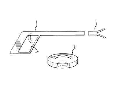
apparatus 1, extracorporeal apparatus 2, and placement apparatus 3. See FIG. 1
[0033] The intracorporeal apparatuses are the set of tools that are used to
attach to an
object or tissue inside a patient's body. They are designed to interact with
the placement
apparatus to place it in the correct position inside the body, an
extracorporeal apparatus to
manipulate it from outside the body, and the object or tissue the surgeon
wishes to
manipulate. FIG. 2 shows a preferred embodiment of an intracorporeal
apparatus. The
preferred embodiment comprises a body 100 of some shape such as a narrow shaft
at least in
one cross section having a size no greater than a trocar. This is necessary as
the
intracorporeal apparatus in its preferred method of use will be passed through
a trocar port
into the patient's body. At one end 102 of the intracorporeal apparatus body,
the apparatus is
adapted to attach to an object or tissue. At the opposing end 104 of the body,
the apparatus is
adapted to engage with a placement apparatus.
[0034] The intracorporeal apparatuses are designed to both physically engage
the
placement apparatus, and respond to energy from an extracorporeal apparatus. A
preferred
embodiment accomplishes this by using magnets 120 disposed in one end 104 of
the
intracorporeal apparatus opposite the fastener end 414. To aid in engaging a
placement
apparatus, the magnet attracts an end of the placement apparatus containing a
material
attracted to the magnet. When the end of the placement apparatus is drawn near
the end of
the intracorporeal apparatus containing the magnet, the two apparatuses are
attracted. If there
is no impeding material located between the placement and intracorporeal
apparatuses, the
-5-
CA 02706860 2010-05-26
WO 2009/070743 PCT/US2008/084991
two apparatuses will contact and stick to each other, end to end.
Advantageously, the
magnetic end 104 of the intracorporeal apparatus is rounded to align axially
with the
placement apparatus. This alignment is imperative to allow the surgeon to
retract both the
placement and intracorporeal apparatuses through the trocar as well as to
allow the interfaces
of the placement apparatus to correctly engage the mating nodes of the
intracorporeal
apparatus. To further aid engaging and aligning the intracorporeal apparatus
to the placement
apparatus, grooves or ridges 108 are placed on the end 104 of the
intracorporeal apparatus to
match the grooves or ridges 108 placed on the end of the placement apparatus.
When the two
apparatuses are pulled proximate to each other by their magnetic attraction,
the grooves and
ridges force the two apparatuses to align with the end of the placement
apparatus slightly
overlapping the end of the intracorporeal apparatus, and forming a tight
connection.
[0035] In a similar alternative embodiment shown in FIG. 2B, a portion of the
body
100 of the intracorporeal apparatus is made of a material responsive to
magnetic energy, and
the magnet is instead disposed in the end of the placement apparatus. With
this embodiment,
the magnet on the placement apparatus may be a permanent magnet or an
electromagnet. The
function performed by this reversed embodiment is identical to the function as
described
above.
[0036] As with all medical devices, sterilization is a key consideration.
Typically,
sterilization of medical equipment is performed using an autoclave, which
amongst other
things, heats the equipment to a temperature higher than any germ can
withstand to kill any
germs present. Unfortunately, some embodiments of the present invention
utilize permanent
magnets, which when heated near a certain temperature known as the Curie
temperature, will
permanently lose their magnetism. Therefore, special consideration in design
and use must
be made to ensure that the tools are both sterile and properly magnetized. The
simplest
procedure to ensure correct magnetization is to use a new device with a fresh
magnet for each
surgery. Alternatively, magnets may be employed having Curie temperatures well
in excess
of sterilization temperatures. Other embodiments of the invention are designed
to
accommodate reuse.
[0037] One such embodiment of the intracorporeal apparatus is shown in FIG. 2C
and
is designed to permit reusing the magnet, but allowing the choice of disposing
the rest. In
this embodiment, the body 100 is at least partially covered by a sterile
plastic shell. The body
100 has a resealable chamber 140 proximate the end 104 which engages the
placement
apparatus, wherein the permanent magnet 120 is placed. In the preferred
embodiment, the
chamber is formed by a cap 142 over a hollows 146 in the body wherein the cap
screws or
-6-
CA 02706860 2010-05-26
WO 2009/070743 PCT/US2008/084991
presses into the rim 144 of the hollows. After a surgery, the surgical team
can remove the
magnet 120 from the intracorporeal apparatus, and determine whether to
sterilize the rest of
the apparatus or discard it. If the team chooses to sterilize its used
intracorporeal apparatuses,
after sterilization, the team may place an available magnet back into the
resealable chamber
140 of the now sterile apparatus. The team may also choose to use an unused
sterile
intracorporeal apparatus, in which case they may place an available magnet
into its resealable
chamber 140 and reseal the chamber, preparing it for surgery. In either
method, the magnet
is removed after surgery, and thus never exposed to the destructive heat of an
autoclave.
[0038] Another embodiment of the intracorporeal apparatus is designed around
reusing the entire apparatus. In this embodiment, the body 100 is made of a
magnetically
inert metal. Like the previous embodiment, the body of the intracorporeal
apparatus has a
resealable chamber 140 proximate the end 104 to house a permanent magnet.
Similarly, in
the preferred embodiment, the resealable chamber 140 is formed by a metal 142
cap over a
hollows 146 in the body wherein the cap screws or presses into the rim 144 of
the hollows
146. After a surgery, the surgical team can remove the magnet 120 from the
intracorporeal
apparatus, and then sterilize this embodiment of the apparatus in an
autoclave. To prepare for
a surgery, the surgical team may use either an unused intracorporeal apparatus
or an
intracorporeal apparatus that has been autoclaved, perfecting preparation for
surgery by
placing an available magnet into the resealable chamber 140 and resealing the
chamber.
Using this embodiment and method, because the magnet was removed after
surgery, it is
never exposed to the destructive heat of an autoclave.
[0039] Known methods of sterilization not involving heating may, of course, be
conveniently employed to sterilize the apparatus of the invention.
[0040] This structure forms the platform for nearly limitless types of
attachments and
fasteners to be constructed for the surgeon's use. Such conceived attachments
include
screws, loops, clips, clamps, and the like. A screw may be useful for piercing
and driving
into a thick or muscular organ, such as a uterus, to gain appropriate traction
to operate. The
screw embodiment of the intracorporeal apparatus shown in FIG. 2D may have a
port 106 on
its end 104 to receive a type of energy and convert it into rotational energy.
The surgeon
using this embodiment may use the rotation of the screw 210 to drive the
intracorporeal
apparatus into the tissue which it is desired to manipulate.
[0041] In a preferred embodiment of the screw intracorporeal apparatus, a
matching
placement apparatus 3 has an interface such as a rotatable knob 220 on the
portion of the
placement apparatus that remains outside the patient's body. Twisting the knob
220
-7-
CA 02706860 2010-05-26
WO 2009/070743 PCT/US2008/084991
manipulates a shaft 230 which connects to a node 240 at the end of the
placement apparatus.
This node engages a second mating node 250 on the screw intracorporeal
apparatus. The
second node 250 is in turn mechanically connected to the screw 210 by an axle
260, which is
adapted to rotate independently from the body 100. Therefore, twisting the
knob 220 on the
placement apparatus rotates the screw 210 on the intracorporeal apparatus. The
length of the
screw 210 may be varied in order to obtain the optimal distance between the
body part which
it is desired to manipulate and the abdominal wall. Another embodiment
includes a non-
human powered drive in the placement apparatus to drive the shaft 230 and
cause the screw
210 to rotate at a higher power than a human can exert without strain.
[0042] Another embodiment of an intracorporeal apparatus, shown in FIGS. 2E
and
2F is in the form of a loop. The loop embodiment may be used to attach to an
object by
placing the loop around the object, tightening the loop and capturing the
object. The loop can
later be loosened to release the object when finished.
[0043] In a preferred embodiment of the loop intracorporeal apparatus, a
matching
placement apparatus 3 has an interface such as a lever, button, or trigger 320
on the portion of
the body that remains outside the patient's body. This trigger 320 drives a
shaft 330 which
connects to a node 340 at the first end of the body. This node engages a
second mating node
350 on the loop intracorporeal apparatus. This node 350 is in turn
mechanically connected to
one or both ends of the loop 300 such that as the node 350 moves towards the
loop, the loop
opens, and as the node moves away from the loop, the loop closes. Therefore,
the loop opens
and closes in response to the surgeon moving the trigger 320 on the placement
apparatus
outside the patient's body.
[0044] An additional feature is a locking mechanism which maintains the
tightened
loop when the intracorporeal apparatus is not engaged with a placement
apparatus. The
mating node 350 on the intracorporeal apparatus is tensioned with a spring
360. This spring
pushes the mating node away from the loop, thus holding the loop closed.
However, when
engaged with a placement apparatus, the surgeon's pressure on the trigger 320
can easily
overcome the spring, forcing the loop to open.
[0045] Inside the intracorporeal apparatus, the loop 300 is actuated by moving
pulleys
310 and stationary pulleys 315. Moving pulleys 310 are mounted on a piston
130. The loop
300 is threaded between moving pulleys 310 and stationary pulleys 315 as shown
in FIG. 2E.
When the mating node 350 is pushed towards the loop, piston 130 and moving
pulleys 310
advance toward the stationary pulleys 315. As shown in FIG. 2F, this shortens
the internal
path loop 300 must take within body 100, allowing more of the loop to extend
outside body
-8-
CA 02706860 2010-05-26
WO 2009/070743 PCT/US2008/084991
100. When the mating node 350 is pushed towards the end 104, piston 130 and
moving
pulleys 310 return back to their extended position as shown in FIG. 2E. As
shown in FIG.
2E, this lengthens the internal path loop 300 must take within body 100,
causing less of the
loop to extend outside the body 100. When force is removed from mating node
350, spring
360 causes piston 130 and mating pulleys 310 to return to this long-path
state.
[0046] A third embodiment of the intracorporeal apparatus is a clip mechanism.
The
clip embodiment can be used to attach a surgical clip to an object proximate
the end of the
clip intracorporeal apparatus while retracting the object, and leaving the
clip in place. In a
preferred embodiment of the clip intracorporeal apparatus, a matching
placement apparatus
has an interface such as a lever, button, or trigger on the portion of the
apparatus that remains
outside the patient's body. This trigger drives a shaft which connects to a
node at the end of
the apparatus. This node engages a second mating node on the clip
intracorporeal apparatus.
The second node is in turn mechanically connected by a piston 130 such that as
the node
moves toward the clip, the clip is expelled from the clip intracorporeal
apparatus and closes
permanently on the object. Therefore, the clip is closed about an object in
response to the
surgeon moving the trigger on the placement apparatus outside the patient's
body.
[0047] A fourth embodiment of the intracorporeal apparatus is a clamp. The
clamp
embodiment can be used to form a simple attachment to an object whereby the
surgeon opens
the clamp and closes it around an object, to maintain its position. The clamp
can later be
opened to release the object.
[0048] In a preferred embodiment of the clamp intracorporeal apparatus, shown
in
FIG. 2A, a matching placement apparatus 3 has an interface such as a lever,
button, or trigger
420 on the portion of the apparatus that remains outside the patient's body.
This trigger 420
manipulates a shaft 430 which connects to a node 440 at the end of the
apparatus. This node
440 engages a second mating node 450 on the clamp intracorporeal apparatus.
The second
node 450 is in turn mechanically connected by a piston 130 to one or both
sides of the clamp
410 such that as the node 450 moves towards the clamp, the clamp opens, and as
the node
moves away from the clamp, the clamp closes. Therefore, the clamp opens and
closes in
response to the surgeon moving the trigger 420 on the placement apparatus
outside the
patient's body. An additional feature is the locking mechanism which holds the
clamp tight
when the intracorporeal apparatus is not engaged with a placement apparatus.
The mating
node 450 on the intracorporeal apparatus is spring tensioned by use of the
clamp 410. The
clamp is preferably constructed of a single rigid material that when at rest
will close down its
tines 414 to a point. For additional grip, the teeth 418 may be disposed near
the end of one or
-9-
CA 02706860 2010-05-26
WO 2009/070743 PCT/US2008/084991
both tines 414. The tines are connected to each other by a flexible filament
416 which is
thread through the body 100 across pulleys 418. The piston 130 is in physical
contact with
the filament 416 inside the body 100. The spring function of the tines 414
keeps the filament
416 in a taut position. This taut filament 416 pushes against the piston 130
away from the
clamp. However, when engaged with a placement apparatus, the surgeon's
pressure on
trigger 420 can easily overcome the tension placed on the filaments by the
tines 414. This
pressure forces mating node 450 and piston 130 to move towards the clamp 410,
stretching
filament 416. As pressure is applied to the filament 416, the tines 414 are
forced to open.
[0049] The placement apparatuses are the tools that are used to physically
position the
intracorporeal apparatuses inside the patient's body and cause them to attach
to objects. The
preferred embodiment, shown in FIGS. 3A and 3B, comprises a body 500 having
some
shape with some length at least in one cross section having a size no greater
than a trocar
being of a length which would allow it to access distant areas within the body
and allow the
surgeon to comfortably operate the portion of the apparatus remaining outside
the patient's
body.
[0050] The preferred embodiment further comprises a connector 502 disposed on
the
end of the body that is placed through the trocar into the patient's body.
This connector is
adapted to engage and disengage any of numerous intracorporeal apparatuses 1.
The
connector is controlled by an engagement interface near the end of the body
that remains
outside the body during surgery. This engagement interface can be a button, an
electrical
connection to an external device or, most preferably, an engagement lever 504
that slides in
the direction along the body's length, and is mechanically attached by a shaft
506 to the
connector 502 at the far end of the body 500. When the engagement lever 504 is
moved
closer to the far end, the connector 502 moves with the engagement lever to
capture and
engage with an intracorporeal apparatus 1. When the lever is moved away from
the far end,
the connector moves with the lever to disengage and release an intracorporeal
apparatus.
[0051] The preferred embodiment also comprises another interface near the end
of the
body that remains outside of the patient's body. This action interface
transmits mechanical
energy from the surgeon or another source outside the body to an
intracorporeal apparatus if
engaged to the placement apparatus. The preferred embodiment for the action
interface is a
lever in the form of a trigger 510 which is spring loaded. The trigger 510 is
mechanically
connected to a node 514 at the far end of the body 500 by a shaft 512. This
node 514 engages
with a mating node 50 on an intracorporeal apparatus 1, the intracorporeal
apparatus then in
-10-
CA 02706860 2010-05-26
WO 2009/070743 PCT/US2008/084991
turn converts the delivered energy for its uses. The action interface may also
be alternatively
an electrical connection to an external device.
[0052] In order to assist engaging with the preferred embodiment of the
intracorporeal apparatus described above, the placement apparatus must have
some
magnetically responsive material to attract the permanent magnet in the
intracorporeal
apparatus. The preferred embodiment thus has a mass of magnetically responsive
material
525 disposed within the body 500 of the placement apparatus near the end that
enters the
patient's body. This magnetically responsive material 525 is mechanically
connected to the
connector 502 and moves toward the end when the engagement interface is moved
towards
the end. The magnetically responsive material 525 moves away from the end
further up the
body 500 when the engagement interface is moved away from the end. As a
result, when the
engagement interface is positioned to engage an intracorporeal apparatus, the
magnetically
responsive material is most proximate the end of the body, and thus more
easily attracted to
the magnet in the intracorporeal apparatus. Furthermore, when the engagement
interface is
positioned to disengage from the intracorporeal apparatus, the magnetically
responsive
material is pulled away and outside the attractive reach of the intracorporeal
apparatus
magnet, thus allowing the two apparatuses to separate.
[0053] It will be appreciated that any magnetically responsive material may be
utilized in accordance with the teaching of the invention. Presently preferred
magnetically
responsive material includes ferrous or iron-containing material, rare-earth
containing
materials, and the like. Exemplary magnetic materials are listed in Table 1.
[0054] In another embodiment, shown in FIGS. 3C and 3D, the placement
apparatus
contains a magnet 530 or electromagnet 540 disposed near the end of the body
that enters the
patient's body. The magnet 530 attracts the magnetically responsive material
in certain
embodiments of the intracorporeal apparatuses, performing the same function in
aiding the
surgeon to engage the intracorporeal apparatus inside the patient's body.
Similarly to the
preferred embodiment, this magnet 530 may be disposed within the shaft of the
body 500 and
mechanically connected to the connector 502. In this way, the magnet 530 moves
closer to
the end of the body 500 when the engagement interface is slid towards the end.
With the
magnet closer to the end, the placement apparatus will more easily attract the
intracorporeal
apparatus. Similarly, the magnet moves into the interior of the body and
further from the end
as the engagement interface is slid away from the end. With the magnet further
from the end,
the intracorporeal apparatus will be less attracted to the placement
apparatus, which will
cause an easy separation.
-11-
CA 02706860 2010-05-26
WO 2009/070743 PCT/US2008/084991
[0055] In the case of using an electromagnet 540, the system can take
advantage of
controlled temporary magnetism. To engage an intracorporeal apparatus 1, the
electromagnet
540 is turned on, and so attracts the magnetically responsive material 120 in
a corresponding
intracorporeal apparatus. Similarly, to disengage the intracorporeal
apparatus, the
electromagnet 540 is turned off. With slight movement from the surgeon, the
intracorporeal
apparatus will no longer be attracted to the placement apparatus, and the two
apparatuses may
be separated. To power the electromagnet, a detachable power supply connects
to the
placement apparatus near the end that remains outside the patient's body. This
power supply
being external to the placement apparatus allows the placement apparatus to be
made smaller.
Furthermore, because it is detachable, the surgical team may detach the power
supply and
sterilize the placement apparatus in an autoclave as they normally would. When
sterile, the
team may then reattach the power supply for use in a subsequent procedure.
[0056] A preferred embodiment also comprises a third interface near the end of
the
body that remains outside of the patient's body. The interface 550 when
activated by the
surgeon causes the connector 502 and any object engaged to it to rotate about
the axis of the
placement apparatus. Utilizing this embodiment, the surgeon's interface 550
may articulate
an intracorporeal apparatus 1 attached to the placement apparatus in a fashion
similar to the
manner in which surgeons currently rotate laparoscopic instruments within a
patient's body.
[0057] In embodiments of the placement apparatus containing their own
permanent
magnets, a similar situation arises as seen in the intracorporeal apparatuses
above involving
sterilization. Typical sterilization in an autoclave may strip the permanent
magnets of their
magnetism. To prevent this in embodiments with permanent magnets, such as
shown in FIG.
3G, the magnet 530 may be placed in a resealable chamber 560 proximate the end
of the body
500 that is passed into the patient's body. In a preferred embodiment, the
resealable chamber
is formed by a cap 562 over a hollow in the body wherein the cap presses into
the rim of the
hollows. After a surgery, the surgical team can remove the magnet 530 from the
placement
apparatus, and sterilize the remainder in an autoclave. In preparation for a
subsequent
surgery, the team may take an unused or an autoclaved placement apparatus,
place an
available magnet into its resealable chamber, and replace the cap on the
chamber, thereby
rendering the placement apparatus ready for utilization in a subsequent
surgery.
[0058] FIG. 3H demonstrates a top view of the connector and its interaction
with the
intracorporeal apparatus. To further aid the engagement and alignment of the
intracorporeal
apparatus to the placement apparatus, grooves or ridges 108 are placed on the
end of the
intracorporeal apparatus to match grooves or ridges 508 on the connector 502.
When the two
-12-
CA 02706860 2010-05-26
WO 2009/070743 PCT/US2008/084991
apparatuses are pulled proximate to each other by their magnetic attraction,
the grooves
and/or ridges 108 force the intracorporeal apparatus to align with the grooves
and ridges 508
on the connector 502 slightly overlapping the end of the intracorporeal
apparatus, and
forming a tight connection. Additionally, the placement apparatus may be
fitted with a
moveable or flexible tab 509 mechanically connected to the engagement
interface. This tab
509 is adapted to fit within a groove 109 on an intracorporeal apparatus in a
mating fashion
when the engagement interface is moved toward the end of the body. Thus, the
tab thus locks
the intracorporeal apparatus to the placement apparatus.
[0059] A third major component of this system is the extracorporeal apparatus.
This
apparatus may be used to position an intracorporeal apparatus and any object
attached to it
within the patient's body. Preferred embodiments of this apparatus comprise a
body of some
shape with an affixed handle and preferably a magnet or other source of
magnetic energy.
The extracorporeal apparatuses require a magnetic field source that can
produce a magnetic
field sufficient to manipulate objects fastened to an intracorporeal
apparatus.
[0060] In the preferred embodiment shown in FIG. 4A, the extracorporeal
apparatus
may be shaped like a disk with the magnet 610 contained in the middle of the
body 600, away
from the surface. In this embodiment, the body forms a shell around the
magnet, comprised
of either a medically inert plastic or a magnetically inert metal or a
combination of both
materials. Both materials are suitable to prevent the magnet from coming in
direct contact
with the patient's body, but also serve the purpose of protecting the magnet.
Many types of
magnets used in the preferred embodiments are so fragile or brittle, that
their own attraction
to another magnet can cause the magnet to disintegrate upon contact. In order
to preserve the
magnet within, the body surrounding the magnet absorbs some of the energy in
the event of
an impact with a hard surface or a corresponding magnaretractor apparatus.
[0061] For sterilization purposes, the extracorporeal apparatus may be
partially
wrapped by a disposable or sterilizable cover 620. As with the placement and
intracorporeal
apparatuses, the use of permanent magnets presents a situation wherein the
typical method of
sterilization, i.e., use of an autoclave may destroy the magnetic properties
of the magnet.
After use in surgery, the surgical team may remove this cover from the
extracorporeal
apparatus, and either discard or sterilize it for later use. In preparation
for a subsequent
surgery, the team then may simply place a new or sterilized cover on an
available
extracorporeal apparatus. In order to ensure that the sterile cover does not
separate from the
extracorporeal apparatus during surgery, it is preferred that the cover
comprise a form-fitting
boot to frictionally adhere to the body of the extracorporeal apparatus.
-13-
CA 02706860 2010-05-26
WO 2009/070743 PCT/US2008/084991
[0062] An additional method to ensure the extracorporeal apparatus is sterile
for a
subsequent surgery is to use an extracorporeal apparatus embodiment having a
resealable
magnet chamber. In this embodiment, the resealable chamber 640 resides in the
central area
of the apparatus body 600. In the preferred embodiment, the chamber is formed
by a cap 642
over a hollows in the body wherein the cap screws or presses into the rim of
the hollows.
After a surgery, the surgical team can remove the magnet 610 from the
extracorporeal
apparatus 2, and determine whether to sterilize the apparatus or discard it.
If the team
chooses to sterilize its used extracorporeal apparatuses, after sterilization,
the team may place
an available magnet back into the resealable chamber 640 of the now sterile
apparatus. The
team may also choose to use an unused sterile extracorporeal apparatus, in
which case they
may place an available magnet into its resealable chamber in preparation for
surgery. In
either method, the magnet is never exposed to the destructive heat of an
autoclave.
[0063] In all of the above embodiments including a permanent magnet, there are
many choices of magnets available with varying benefits and detriments to each
of their
respective uses. The magnets of the extracorporeal apparatuses must be strong
enough to
exert sufficient pulling (or pushing) force to permit manipulation of the
desired object within
the body cavity from a distance of several centimeters. For example, in
performing a
hysterectomy on a fibroid uterus, the magnet pulling an attached
intracorporeal apparatus
must reach through as much as 5 centimeters or even more of the patient's body
to cause the
uterus to move.
[0064] While this situation suggests the use of a larger, more powerful
magnet, other
considerations require the magnet to be as weak as possible without disrupting
function. For
instance, it is very likely that the surgeon will place more than one
intracorporeal apparatus
inside the patient's body. An extremely strong magnet may disadvantageously
attract both
the intended and an unintended intracorporeal apparatus, as well as any other
objects
containing magnetically responsive material in the room. Furthermore, such a
strong magnet
will also be physically larger than necessary to perform the procedure,
thereby rendering it
too unwieldy to control or anchor. A third consideration is that a very strong
magnet will
apply a considerable force to an object attracted to it, which may pinch
tissue between the
object and the magnet, with enough force to cause damage to the patient.
[0065] Accordingly, the present invention includes a set of extracorporeal
apparatuses
with magnets of varying sizes, shapes and materials, or an adjustable
electromagnet. The
first consideration for a surgical team in choosing which type of magnets to
use concerns
whether they will reuse the tools, and if so, how they will sterilize them. A
surgical team
-14-
CA 02706860 2010-05-26
WO 2009/070743 PCT/US2008/084991
choosing to discard used extracorporeal apparatuses is only limited in its
choice by the
expense of individual magnets, and therefore needs only consider the magnetic
strength
required for this particular patient or procedure.
[0066] Surgical teams that choose to reuse however must consider the Curie
temperature for the magnet they wish to use, and a particular sterilization
method. As
mentioned above, using an autoclave may destroy a magnet's magnetism.
Therefore, the
team has three options for reuse. The first option is to choose a magnet with
a Curie
temperature much higher than their autoclave can generate, such as Samarium-
cobalt or
Alnico magnets. With this option, the team may simply place the entire
apparatus into the
autoclave as they would any other equipment. For many purposes, this may be an
adequate
solution. However, both Samarium-cobalt and Alnico magnets are weaker than
Neodymium
magnets, and such strength may be necessary for patients with thick adipose
tissue or in
procedures that require manipulation of deeply situated or heavy objects.
[0067] The second option is to choose an extracorporeal apparatus having a
removable magnet in a resealable chamber. With this option, the team removes
the magnet
from the apparatus after use. The apparatus then may be placed in the
autoclave as the team
typically would to sterilize equipment. After sterilization, the team would
then place the
magnet back into the apparatus prior to conducting another surgery. There is
no limitation to
the team placing the magnet in the same apparatus, as the magnet may be placed
in any
available apparatuses.. This option will work well in any situation, however
the surgical
team must take the necessary precautions .
[0068] The final option is to use permanently positioned magnets within the
apparatus. After use, the surgical team may place the entire extracorporeal
apparatus into the
autoclave, without regard to Curie temperatures until sterilization is
achieved. Since the
magnet embedded in the apparatus may have been demagnetized, before use, the
team must
place the apparatus into a remagnetizer to return the magnet to its full
magnetic capabilities.
The team may perform this on-site, or return the apparatus to an appropriate
vendor who can
perform a remagnetizing service to re-magnetize the magnets. A preferred
embodiment of a
remagnetizer includes a body which physically mates with the extracorporeal
apparatus to
hold it in one position during the re-magnetization process. The remagnetizer
exposes the
magnet within the magnaretractor apparatus to a high-intensity magnetic field,
which causes
the magnet to retain its original magnetic field. This option may similarly be
used to sterilize
and re-magnetize intracorporeal and placement apparatuses.
-15-
CA 02706860 2010-05-26
WO 2009/070743 PCT/US2008/084991
Table 1 - Exemplary magnets and their characteristics
Material Curie Characteristics
Temp.
Cobalt (Co) 1115 C Very high Curie temp.
Low strength
Alnico 800 C High Curie temp.
Much weaker than SmCo and NIB magnets
Much stronger than other non-rare earth magnets
Iron (Fe) 770 C High Curie temp.
Low strength
Samarium-cobalt 680 to High Curie temp.
(SmCo) 800 C Very high strength
More expensive than NIB magnets
Weaker than NIB magnets
Very brittle
Nickel (Ni) 354 C Low strength
Low Curie temp.
Neodymium 320 C Strongest permanent magnet currently sold commercially
(NdFeB or NIB) Less expensive than SmCo magnets
Low Curie temperature
Brittle but less so than SmCo
Highly corrosive
[0069] While the size and material of the magnet determines its strength, the
shape
has an effect on how much the magnetic field "falls off' over distance. For
example, a
magnet shaped like a long rod may be strong enough to cause an object weighing
1 kilogram
from one centimeter away to accelerate towards the magnet. This same magnet
can only
cause the same acceleration on an object weighing 250 grams from two
centimeters away or
40 grams from five centimeters away. In this situation, the strength of the
magnetic field is
said to fall off with the square of the distance, giving this magnet a deep
reach. Although a
magnet having a different shape may also be able to cause an object weighing 1
kilogram
from one centimeter away to accelerate towards it, however, at two
centimeters, it may only
have the capacity to cause the same acceleration on an object weighing 125
grams, and from
five centimeters the magnet may only cause the same acceleration on an object
weighing 8
-16-
CA 02706860 2010-05-26
WO 2009/070743 PCT/US2008/084991
grams. In this situation, the strength of the magnetic field is said to fall
off with the cube of
the distance , i. e., a shallower reach. Thus, the surgeon will have the
option of choosing an
extracorporeal apparatus with a deeper or shallower reach.
[0070] During surgery, the surgeon may use special trocars with graduations to
measure the thickness of the abdominal walls of the patient's body. With that
measurement
and the surgeon's knowledge of the approximate weight of the object to be
moved, the
surgeon may choose the appropriate extracorporeal apparatus having a magnet of
the required
strength amongst the plurality of available apparatuses.
[0071] The extracorporeal apparatus may be fine tuned by disposing the magnet
on an
articulable joint. In this embodiment, preferably utilizing a cup shape as
shown in FIG. 4B,
the magnet 610 may be moved closer or further away from the patient's body by
manipulating the articulable joint 660. This way, the surgeon may exact
greater or lesser
force on an object held by an intracorporeal apparatus within the body.
Additionally, the
surgeon may use intracorporeal apparatuses containing its own magnets, which
will interact
with the magnet 610 in the extracorporeal apparatus 2. Using the articulable
joint 660, the
surgeon may rotate the magnet of the extracorporeal apparatus 660, which would
cause the
magnet of the nearby intracorporeal apparatus to rotate in sympathy. The
result is that the
surgeon can manipulate the attitude of the object within the patient's body by
articulating the
magnet attached to the extracorporeal apparatus.
[0072] Another embodiment shown in FIG. 4C uses an electromagnet 615 as the
source of magnetic energy. In this embodiment, the strength of the
electromagnet's 615
magnetic field is adjustable to allow the surgeon to choose the smallest field
required to
position a single intracorporeal apparatus, and not interfere with other
apparatuses or other
magnetically responsive objects. A detachable power supply cable 617 provides
power to the
electromagnet 615.
[0073] To ease using the extracorporeal apparatus, the surgeon may lubricate
the
surface 670 touching the patient's body to allow it to move more easily, and
anchor the
apparatus to the body, the surgical drape, the surgical table, or another
fixed object, to
prevent the apparatus from moving once in place.
[0074] Anchoring the extracorporeal apparatus in a fixed position may also be
accomplished by using an air pump. The preferred embodiments shown in FIGS.
4A, 4B and
4C dispose a port 650 on one side of the extracorporeal apparatus which may be
connect to
an air pump. This port allows the surgeon to position the extracorporeal
apparatus 2 on the
desired point on the exterior of the patient's body. Then using the air pump,
the surgeon may
-17-
CA 02706860 2010-05-26
WO 2009/070743 PCT/US2008/084991
pump air from beneath port 650, thereby decreasing the pressure between the
extracorporeal
apparatus 2 and the patient's body. The resulting pressure differential will
gently lock the
extracorporeal apparatus in position on the patient's body. When the surgeon
wishes to
remove the apparatus, a release valve on the air pump may be opened, allowing
normal
pressure to return to the region between the apparatus and the patient's body,
thus unlocking
the apparatus.
[0075] The extracorporeal apparatus may also be anchored to the patient's body
by
use of a medical adhesive. A semi-permanent adhesive may be either placed
directly on the
bottom surface 670 of the extracorporeal apparatus 2, or alternatively, the
adhesive may be
placed around the edge of the extracorporeal apparatus as shown in FIG. 4D.
The rim may be
moveable to align with the lower surface 670 of the extracorporeal apparatus 2
when
adhering to the patient's body, or retracted above the lower surface 670 of
the extracorporeal
apparatus when not adhering to the patient's body.
[0076] In a standard laparoscopy for endometriosis, three ports are opened on
the
patient's abdomen -- the camera is placed through an umbilical port and two
lower quadrant
ports are used for instrumentation. Often, there is endometriosis deep in the
pelvis or behind
the ovary. In order to access the endometriosis and excise or fulgurate it,
the surgeon must
retract the ovary through one port. The peritoneum must be tented up before
the
endometriosis can be excised or fulgurated in order to prevent damaging the
underlying
structures.
[0077] With the present invention, the surgeon may start by placing the three
ports: a
camera in the umbilical port, and two operative ports in the lower quadrants.
The surgeon
then may engage a clamp intracorporeal apparatus to a placement apparatus.
Using one of
the operative ports, the surgeon may feed the combination through the trocar
into the
patient's body, and place the clamp on the ovary to be retracted. The surgeon
then is able to
place an extracorporeal apparatus on the exterior surface of the abdomen. The
magnetic field
attracts the clamp and the surgeon is able to guide the ovary towards the
extracorporeal
apparatus. The extracorporeal apparatus may be locked into position using an
adhesive on
the extracorporeal apparatus rim or an anchor. With the ovary now retracted
against the
abdominal wall and maintained by the extracorporeal apparatus, the surgeon is
able to
disengage the clamp intracorporeal apparatus from the placement apparatus and
retract the
placement apparatus back through the trocar and out of the patient's body. The
ovary will
now remain retracted against the interior surface of the anterior abdominal
wall, well outside
of the surgical field, and without the inclusion of a large intra-abdominal
instrument.
-18-
CA 02706860 2010-05-26
WO 2009/070743 PCT/US2008/084991
Accordingly, the surgeon will only need two intra-abdominal instruments, and
may control
all of the instruments in the operative field without assistance. This also
beneficially results
in less instrument clutter in the operative field.
[0078] The present invention can also be very beneficial when performing a
laparoscopic hysterectomy. In an open abdominal hysterectomy, a cork screw is
often placed
in the fundus of the uterus and used for upward traction in order to decrease
bleeding. The
traction on the uterus also makes it much easier to access the lateral sides
of the uterus and
suture and ligate the uterine arteries and cardinal ligaments. One of the
difficulties in
performing a laparoscopic hysterectomy is that there is no way to retract the
uterus in a
similar fashion. It is often difficult to surgically place an extra port and
use a grasper to
retract the uterus. The additional grasper often gets in the way of the other
intra-abdominal
instruments, which are being used to carry out the dissection. Also, the
surgeon is physically
unable to manipulate more than two instruments at a time. Lastly, a surgeon
often
experiences difficulty in trying to manipulate the uterus utilizing a grasper.
[0079] The present invention, allows the surgeon the ability to retract the
uterus in the
same fashion as if the surgeon were performing an open abdominal hysterectomy.
Initially,
the surgeon would engage a screw intracorporeal apparatus with a placement
apparatus, and
insert the combination through a trocar into the patient's body. The surgeon
is then able to
position the screw and twist it into the fundus of the uterus. An
extracorporeal apparatus may
then be placed on the external anterior abdominal wall. The surgeon must
choose an
extracorporeal apparatus with a magnet strong enough to attract the muscular
and massive
uterus. The screw intracorporeal apparatus and the attached uterus would then
be attracted
towards the magnetic field of the extracorporeal apparatus. Accordingly, the
extracorporeal
apparatus would essentially provide upwards traction on the uterus similar to
an open
abdominal case. Furthermore, the extracorporeal apparatus could be moved
laterally as
needed to move the uterus and allow for easy access to the lateral aspects of
the uterus and
cervix. With the screw intracorporeal apparatus attached to the uterus, the
surgeon may
disengage and retract the placement apparatus through the trocar and out of
the patient's
body, thus freeing space within the body for other intra-abdominal
instruments.
[0080] The present invention can also be used to increase performance when
conducting a salpingectomy for a tubal ligation or an ectopic pregnancy. The
current
procedure is conducted with use of three ports: an umbilical port for a
camera, and two within
which to operate. The procedure requires a surgical assistant to grasp and
hold the tube while
the surgeon performs the resection. However the present invention allows the
surgeon to
-19-
CA 02706860 2010-05-26
WO 2009/070743 PCT/US2008/084991
perform the procedure without any assistance, and utilizing only two ports: an
umbilical port
for the camera, and a superpubic operative port. Initially, the surgeon would
begin by
engaging a clamp intracorporeal apparatus to a placement apparatus, and
passing the
combination through a trocar into the patient's body. At this point, the
surgeon can maneuver
the clamp onto the area of the tube that is to be resected. An extracorporeal
apparatus placed
on the external abdominal wall could then be used to retract and grasp the
tube. With the
tube retracted, the surgeon may disengage the placement apparatus and retract
it through the
trocar and out of the patient's body, thereby freeing up space for a different
intra-abdominal
apparatus. Next, a harmonic scalpel or other such device would be used to
resect the desired
portion of the tube. Accordingly, the need for an extra port and a surgical
assistant is
eliminated. Post-completion of the resection, the surgeon may then reinsert
the placement
apparatus through the trocar into the patient's body, and manipulate the clamp
intracorporeal
apparatus still attached to the tube. The surgeon is able to then re-engage
the placement
apparatus with the intracorporeal apparatus, and release the clamp from the
tube. Finally, the
surgeon may remove the resected tube from the abdominal cavity, retract the
combination of
the placement apparatus and the clamp through the trocar and seal the ports
used in the
surgical procedure.
[0081] The present invention may also be used to help the surgeon avoid many
of the
common complications of laparoscopic surgery. A common complication in
laparoscopic
surgery is ureteral damage. Ureteral damage, if not promptly treated, may
result in damage to
renal function and possibly loss of the kidney entirely. The present invention
prevents
damage to a ureter by the insertion of an intracorporeal apparatus such as a
toothless clamp or
a loop to move a ureter away from the surgical field.
[0082] The present invention may also be used in general surgical procedures.
For
example, laparoscopic bariatric surgery can be made more efficient using this
invention.
During a laparoscopic bariatric procedure, the surgeon must retract the liver.
Presently, this
retractor requires the use of an operative port. The present invention allows
the surgeon the
ability to retract the liver without the use of a trocar-occupying instrument.
Accordingly, the
surgery could be performed with a reduced number of ports and reduced intra-
abdominal
congestion.
[0083] The present invention may also be used in laparoscopic procedures
performed
on animals. For example, laparoscopic surgery routinely performed on baboons
may be
carried out more efficiently by means of the present invention. During
diagnostic
laparoscopic procedures, it has been discovered that the uterus and ovaries of
a baboon are
-20-
CA 02706860 2010-05-26
WO 2009/070743 PCT/US2008/084991
more mobile than those of humans. The present invention enables the surgeon to
retract the
uterus or ovaries of a baboon without the use of grasping forceps. This is
preferable, because
the use of grasping forceps has been reported to result in slight round
ligament bleeding in
some laparoscopic procedures performed on baboons. Laparoscopic surgery is
also
performed on other animals, including mammals such as dogs, llamas, alpacas,
mares, lions
and cows. The present invention will enable surgeons to accomplish such
operations in a
more efficient manner, as in humans.
[0084] Numerous additional advantages may be realized by those having ordinary
skill in the art, for any situation in which a surgeon has thorough knowledge
of regional
anatomy and requires moving internal objects or organs so as to gain access to
another object
or organ in the body.
-21-