Note: Descriptions are shown in the official language in which they were submitted.
CA 02706908 2010-05-26
WO 2009/072789
PCT/KR2008/007108
F200811-0007
PHYSICAL BROADCAST CHANNEL (PBCH) TRANSMISSION FOR RELIABLE
DETECTION OF ANTENNA CONFIGURATION
TECHNICAL FIELD OF THE INVENTION
[001] The present application relates generally to wireless
communications and, more specifically, to a technique for improved
interference power estimation.
BACKGROUND OF THE INVENTION
[002] Modern communication systems include transceivers that
comprise a plurality of antennas arranged in a plurality of
configurations. In order to convey information using these
transceivers, information relating to the configuration of the
antennas needs to be communicated to the device communicating with
the transceiver. However, this communication requires considerable
bandwidth and is not easily done. The conveyance of the configuration
of the antennas represents significant overhead to a communication
system. Therefore, there is a need in the art for an improved system
and method for conveying antenna configuration information.
SUMMARY OF THE INVENTION
[003] In one embodiment, systems and methods for transmitting
data related to the configuration of transmit antennas are disclosed.
- 1 -
CA 02706908 2010-05-26
WO 2009/072789 PCT/KR2008/007108
F200811-0007
These methods may include obtaining a data for transmission,
encoding the data and modulating the data. During the modulating
of the data, the data may be configured in such a way as to convey
the configuration of the data through the modulation of the data.
These methods may also include obtaining an antenna configuration,
obtaining a representation of the antenna configuration, and masking
the data with an error correcting code, where the mask corresponds
to the antenna configuration.
[004] In another embodiment, a wireless communication network
is disclosed that comprises a plurality of base stations capable
of wireless communication with a plurality of subscriber stations
within a coverage area of the network. In these embodiments at least
one of the plurality of base stations is capable of encoding a
transmission antenna configuration into a QPSK constellation and
transmitting the QPSK constellation. In addition, the transmission
may be masked with an error correction code that corresponds to a
transmit antenna configuration.
[005] In yet another embodiment, systems and methods are
disclosed with a base station capable of wireless communication with
a plurality of subscriber stations within a coverage area of a network.
In these embodiments, the base station is capable of transmitting
data with at least one antenna, encoding a configuration of the at
- 2 -
least one antenna into a data stream, and transmitting the data stream.
These methods may further comprise transmitting an error correction
code that has been masked to represent the configuration of the
transmit antennas.
In some embodiments of the present invention, there is
provided a base station, comprising:
a processor configured to generate a cyclic redundancy
check (CRC) for a transport block to be transmitted on a Physical
Broadcast Channel (PBCH) and to mask the CRC:
with a first sequence when the base station is configured
to transmit using one antenna,
with a second sequence different than the first sequence
when the base station is configured to transmit using two
antennas, and
with a third sequence different from the first and second
sequences when the base station is configured to transmit using
four antennas; and
a transmitter configured to transmit the transport block
and the masked CRC on the PBCH.
In some embodiments of the present invention, there is
provided a method of transmitting by a base station, comprising:
generating, in a base station, a cyclic redundancy check
(CRC) for a transport block to be transmitted on a Physical
Broadcast Channel (PBCH);
masking, in the base station, the CRC:
with a first sequence when the base station is
configured to transmit using one antenna,
- 3 -
CA 2706908 2017-10-17
with a second sequence different than the first
sequence when the base station is configured to transmit
using two antennas, and
with a third sequence different from the first and
second sequences when the base station is configured to
transmit using four antennas; and
transmitting, from the base station, the transport block
and the masked CRC on the PBCH.
In some embodiments of the present invention, there is
provided a user equipment, comprising:
a receiver configured to receive, on a Physical Broadcast
Channel (PBCH), a transport block and a masked cyclic redundancy
check (CRC) generated on the transport block; and
a processor configured to generate a CRC for the received
transport block, to mask the generated CRC with each of first,
second and third sequences to generate first, second and third
masked CRC, to compare the first, second and third masked CRCs to
the received masked CRC, and to determine that the transport
block and the masked CRC were transmitted:
using one antenna when the first masked CRC matches
the received masked CRC,
using two antennas when the second masked CRC matches
the received masked CRC, and
using four antennas when the third masked CRC matches
the received masked CRC.
In some embodiments of the present invention, there is
provided a method of receiving by a user equipment, comprising:
- 3a -
CA 2706908 2017-10-17
receiving, at the user equipment on a Physical Broadcast
Channel (PBCH), a transport block and a masked cyclic redundancy
check (CRC) generated on the transport block; and
generating, in the user equipment, a CRC for the received
transport block;
masking, in the user equipment, the generated CRC with each
of first, second and third sequences to generate first, second
and third masked CRCs;
comparing, in the user equipment, the first, second and
third masked CRCs to the received masked CRC; and
determining, in the user equipment, that the transport
block and the masked CRC were transmitted:
using one antenna when the first masked CRC matches
the received masked CRC,
using two antennas when the second masked CRC matches
the received masked CRC, and
using four antennas when the third masked CRC matches
the received masked CRC.
In some embodiments of the present invention, there is
provided a base station, comprising:
a processor configured to mask a cyclic redundancy
check(CRC), corresponding to a transport block to be transmitted
on a physical broadcast channel (PBCH), with a sequence from a
plurality of sequences corresponding to a configuration of one or
more transmit antennas of the base station, wherein each of the
plurality of sequences is associated with a number of transmit
antennas; and
- 3b -
CA 2706908 2017-10-17
a transmitter configured to transmit the transport block
and the masked CRC on the PBCH.
In some embodiments of the present invention, there is
provided a method of transmitting by a base station, comprising:
masking a cyclic redundancy check (CRC), corresponding to a
transport block to be transmitted on a physical broadcast channel
(PBCH), with a sequence from a plurality of sequences
corresponding to a configuration of one or more transmit antennas
of a base station, wherein each of the plurality of sequences is
associated with a number of transmit antennas; and
transmitting the transport block and the masked CRC on the
PBCH.
[006] Before undertaking the DETAILED DESCRIPTION OF THE
INVENTION below, it may be advantageous to set forth definitions
of certain words and phrases used throughout this patent document:
the terms "include" and "comprise," as well as derivatives thereof,
mean inclusion without limitation; the term "or," is inclusive,
meaning and/or; the phrases "associated with" and "associated
therewith," as well as derivatives thereof, may mean to include,
be included within, interconnect with, contain, be contained within,
connect to or with, couple to or with, be communicable with, cooperate
with, interleave, juxtapose, be proximate to, be bound to or with,
have, have a property of, or the like; and the term "controller"
means any device, system or part thereof that controls at least one
- 3c -
CA 2706908 2017-10-17
operation, such a device may be implemented in hardware, firmware
or software, or some combination of at least two of the same. It
should be noted that the functionality associated with any particular
controller may be centralized or distributed, whether locally or
remotely. Definitions for certain words and phrases are provided
throughout this patent document, those of ordinary skill in the art
- 3d -
CA 2706908 2017-10-17
CA 02706908 2010-05-26
WO 2009/072789
PCT/KR2008/007108
F200811-0007
should understand that in many, if not most instances, such
definitions apply to prior, as well as future uses of such defined
words and phrases.
BRIEF DESCRIPTION OF THE DRAWINGS
[007] For a more complete understanding of the present disclosure
and its advantages, reference is now made to the following description
taken in conjunction with the accompanying drawings, in which like
reference numerals represent like parts:
[008] FIGURE 1 illustrates an exemplary wireless network that
transmits ACK/NACK messages in the uplink according to the principles
of the present disclosure;
[009] FIGURE 2 is a high-level diagram of an OFDMA transmitter
according to one embodiment of the present disclosure;
[010] FIGURE 3 is a high-level diagram of an OFDMA receiver
according to one embodiment of the present disclosure;
[011] FIGURE 4 is a high-level diagram of a transmission chain
according to one embodiment of the present disclosure;
[012] FIGURE 5 is a diagram of a constellation mapping of QPSK
modulation according to one embodiment of the present disclosure;
- 4 -
CA 02706908 2010-05-26
WO 2009/072789
PCT/KR2008/007108
F200811-0007
[013] FIGURE 6 is a diagram of a modified constellation mapping
of QPSK modulation according to one embodiment of the present
disclosure;
[014] FIGURE 7 is a diagram of a second modified constellation
mapping of QPSK modulation according to one embodiment of the present
disclosure;
[015] FIGURE 8 is a diagram of a third modified constellation
mapping of QPSK modulation according to one embodiment of the present
disclosure;
[016] FIGURE 9 is a diagram of a fourth modified constellation
mapping of QPSK modulation according to one embodiment of the present
disclosure;
[017] FIGURE 10 is an example of a transport chain illustrating
constellation remapping according to one embodiment of the present
disclosure;
[018] FIGURE 11 is a flowchart of the interpretation of signals
by a subscriber station according to one embodiment of the present
disclosure;
[019] FIGURE 12 is a block diagram of the mapping of
constellations and CRC masking according to one embodiment of the
present disclosure;
- 5 -
CA 02706908 2010-05-26
WO 2009/072789
PCT/KR2008/007108
F200811-0007
[020] FIGURE 13 is a block diagram of CRC masking according to
one embodiment of the present disclosure;
[021] FIGURE 14 is a flowchart of the interpretation of signals
by a subscriber station according to one embodiment of the present
disclosure;
[022] FIGURE 15 is a block diagram of the remapping of
constellations and CRC mapping according to one embodiment of the
present disclosure; and
[023] FIGURE 16 is a flowchart of the interpretation of signals
by a subscriber station using both a QPSK constellation and a CRC
mask of the present disclosure.
DETAILED DESCRIPTION OF THE INVENTION
[024] FIGURES 1 through 16, discussed below, and the various
embodiments used to describe the principles of the present disclosure
in this patent document are by way of illustration only and should
not be construed in any way to limit the scope of the disclosure.
Those skilled in the art will understand that the principles of
the present disclosure may be implemented in any suitably arranged
wireless communication system.
[025] FIGURE 1 illustrates exemplary wireless network 100, which
transmits ACK/NACK messages according to the principles of the
- 6 -
CA 02706908 2010-05-26
WO 2009/072789
PCT/KR2008/007108
F200811-0007
present disclosure. In the illustrated embodiment, wireless network
100 includes base station (BS) 101, base station (BS) 102, base
station (BS) 103, and other similar base stations (not shown). Base
station 101 is in communication with base station 102 and base station
103. Base station 101 is also in communication with Internet 130
or a similar IS-based network (not shown).
[026] Base station 102 provides wireless broadband access (via
base station 101) to Internet 130 to a first plurality of subscriber
stations within coverage area 120 of base station 102. The first
plurality of subscriber stations includes subscriber station 111,
which may be located in a small business (SB), subscriber station
112, which may be located in an enterprise (E), subscriber station
113, which may be located in a WiFi hotspot (HS), subscriber station
114, which may be located in a first residence (R), subscriber station
115, which may be located in a second residence (R), and subscriber
station 116, which may be a mobile device (M), such as a cell phone,
a wireless laptop, a wireless FDA, or the like.
[027] Base station 103 provides wireless broadband access (via
base station 101) to Internet 130 to a second plurality of subscriber
stations within coverage area 125 of base station 103. The second
plurality of subscriber stations includes subscriber station 115
and subscriber station 116. In an exemplary embodiment, base stations
- 7 -
CA 02706908 2010-05-26
WO 2009/072789 PCT/KR2008/007108
F200811-0007
101-103 may communicate with each other and with subscriber stations
111-116 using OFDM or OFDMA techniques.
[028] Base station 101 may be in communication with either a
greater number or a lesser number of base stations. Furthermore,
while only six subscriber stations are depicted in FIGURE 1, it is
understood that wireless network 100 may provide wireless broadband
access to additional subscriber stations. It is noted that subscriber
station 115 and subscriber station 116 are located on the edges of
both coverage area 120 and coverage area 125. Subscriber station
115 and subscriber station 116 each communicate with both base station
102 and base station 103 and may be said to be operating in handoff
mode, as known to those of skill in the art.
[029] Subscriber stations 111-116 may access voice, data, video,
video conferencing, and/or other broadband services via Internet
130. In an exemplary embodiment, one or more of subscriber stations
111-116 may be associated with an access point (AP) of a WiFi WLAN.
Subscriber station 116 may be any of a number of mobile devices,
including a wireless-enabled laptop computer, personal data
assistant, notebook, handheld device, or other wireless-enabled
device. Subscriber stations 114 and 115 may be, for example, a
wireless-enabled personal computer (PC), a laptop computer, a gateway,
or another device.
- 8 -
CA 02706908 2010-05-26
WO 2009/072789
PCT/KR2008/007108
F200811-0007
[030] FIGURE 2 is a high-level diagram of an orthogonal frequency
division multiple access (OFDMA) transmit path. FIGURE 3
is a
high-level diagram of an orthogonal frequency division multiple
access (OFDMA) receive path. In FIGURES 2 and 3, the OFDMA transmit
path is implemented in base station (BS) 102 and the OFDMA receive
path is implemented in subscriber station (SS) 116 for the purposes
of illustration and explanation only. However, it will be understood
by those skilled in the art that the OFDMA receive path may also
be implemented in ES 102 and the OFDMA transmit path may be implemented
in SS 116.
[031] The transmit path in BS 102 comprises channel coding and
modulation block 205, serial-to-parallel (S-to-P) block 210, Size
N Inverse Fast Fourier Transform (IFFT) block 215, parallel-to-serial
(P-to-S) block 220, add cyclic prefix block 225, up-converter (DC)
230. The receive path in SS 116 comprises down-converter (DC) 255,
remove cyclic prefix block 260, serial-to-parallel (S-to-P) block
265, Size N Fast Fourier Transform (FFT) block 270,
parallel-to-serial (P-to-S) block 275, channel decoding and
demodulation block 280.
[032] At least some of the components in FIGURES 2 and 3 may
be implemented in software while other components may be implemented
by configurable hardware or a mixture of software and configurable
- 9 -
CA 02706908 2010-05-26
WO 2009/072789
PCT/KR2008/007108
F200811-0007
hardware. In particular, it is noted that the FFT blocks and the
IFFT blocks described in this disclosure document may be implemented
as configurable software algorithms, where the value of Size N may
be modified according to the implementation.
[033] Furthermore, although this disclosure is directed to an
embodiment that implements the Fast Fourier Transform and the Inverse
Fast Fourier Transform, this is by way of illustration only and should
not be construed to limit the scope of the disclosure. It will be
appreciated that in an alternate embodiment of the disclosure, the
Fast Fourier Transform functions and the Inverse Fast Fourier
Transform functions may easily be replaced by Discrete Fourier
Transform (DFT) functions and Inverse Discrete Fourier Transform
(IDFT) functions, respectively. It will be appreciated that for
DFT and IDFT functions, the value of the 19 variable may be any integer
number (i.e., 1, 2, 3, 4, etc.), while for FFT and IFFT functions,
the value of the N variable may be any integer number that is a power
of two (i.e., 1, 2, 4, 8, 16, etc.).
[034] In BS 102, channel coding and modulation block 205 receives
a set of information bits, applies coding (e.g., Turbo coding) and
modulates (e.g., QPSK, QM) the input bits to produce a sequence
of frequency-domain modulation symbols. Serial-to-parallel block
210 converts (i.e., de-multiplexes) the serial modulated symbols
- 10 -
CA 02706908 2010-05-26
WO 2009/072789
PCT/KR2008/007108
F200811-0007
to parallel data to produce N parallel symbol streams where N is
the IFFT/FFT size used in BS 102 and SS 116. Size N IFFT block 215
then performs an IFFT operation on the N parallel symbol streams
to produce time-domain output signals. Parallel-to-serial block
220 converts (i.e., multiplexes) the parallel time-domain output
symbols from Size N IFFT block 215 to produce a serial time-domain
signal. Add cyclic prefix block 225 then inserts a cyclic prefix
to the time-domain signal. Finally, up-converter 230 modulates (i.e.,
up-converts) the output of add cyclic prefix block 225 to RF frequency
for transmission via a wireless channel. The signal may also be
filtered at baseband before conversion to RF frequency.
[035] The transmitted RF signal arrives at SS 116 after passing
through the wireless channel and reverse operations to those at BS
102 are performed. Down-converter 255 down-converts the received
signal to baseband frequency and remove cyclic prefix block 260
removes the cyclic prefix to produce the serial time-domain baseband
signal. Serial-
to-parallel block 265 converts the time-domain
baseband signal to parallel time domain signals. Size N FFT block
270 then performs an FFT algorithm to produce N parallel
frequency-domain signals. Parallel-to-serial block 275 converts
the parallel frequency-domain signals to a sequence of modulated
data symbols. Channel
decoding and demodulation block 280
- 11 -
CA 02706908 2010-05-26
WO 2009/072789
PCT/KR2008/007108
F200811-0007
demodulates and then decodes the modulated symbols to recover the
original input data stream.
[036] Each of base stations 101-103 may implement a transmit
path that is analogous to transmitting in the downlink to subscriber
stations 111-116 and may implement a receive path that is analogous
to receiving in the uplink from subscriber stations 111-116.
Similarly, each one of subscriber stations 111-116 may implement
a transmit path corresponding to the architecture for transmitting
in the uplink to base stations 101-103 and may implement a receive
path corresponding to the architecture for receiving in the downlink
from base stations 101-103.
[037] The present disclosure describes methods and systems to
convey information relating to base station configuration to
subscriber stations and, more specifically, to relaying base station
antenna configuration to subscriber stations. This information can
be conveyed through a plurality of methods, including placing antenna
configuration into a quadrature-phase shift keying (QPSK)
constellation (e.g., n-quadrature amplitude modulation (QAM) signal,
wherein n is 2^x) and placing antenna configuration into the error
correction data (e.g., cyclic redundancy check (CRC) data). By
encoding antenna information into either the QPSK constellation or
the error correction data, the base stations 101-103 can convey base
- 12 -
CA 02706908 2010-05-26
WO 2009/072789
PCT/KR2008/007108
F200811-0007
stations 101-103 antenna configuration without having to separately
transmit antenna configuration. These systems and methods allow
for the reduction of overhead while ensuring reliable communication
between base stations 101-103 and a plurality of subscriber stations.
[038] In some embodiments disclosed herein, data is transmitted
using QAM. QAM is a modulation scheme which conveys data by modulating
the amplitude of two carrier waves. These two waves are referred
to as quadrature carriers, and are generally out of phase with each
other by 90 degrees. QAM may be represented by a constellation that
comprises 2^x points, where x is an integer greater than 1. In the
embodiments discussed herein, the constellations discussed will be
four point constellations (4-QAM). In a 4-QAM constellation a 2
dimensional graph is represented with one point in each quadrant
of the 2 dimensional graph. However, it is explicitly understood
that the innovations discussed herein may be used with any modulation
scheme with any number of points in the constellation. It is further
understood that with constellations with more than four points
additional information (e.g., reference power signal) relating to
the configuration of the base stations 101-103 may be conveyed
consistent with the disclosed systems and methods.
[039] It is understood that the transmitter within base stations
101-103 performs a plurality of functions prior to actually
- 13 -
CA 02706908 2010-05-26
WO 2009/072789
PCT/KR2008/007108
F200811-0007
transmitting data. In the 4-QAM embodiment, QAM modulated symbols
are serial-to-parallel converted and input to an inverse fast Fourier
transform (IFFT) . At the output of the IFFT, N time-domain samples
are obtained. In the disclosed embodiments, N refers to the IFFT/
fast Fourier transform (FFT) size used by the OFDM system. The signal
after IFFT is parallel-to-serial converted and a cyclic prefix (OF)
is added to the signal sequence. The resulting sequence of samples
is referred to as an OFDM symbol.
[040] At the receiver within the subscriber station, this process
is reversed, and the cyclic prefix is first removed. Then the signal
is serial-to-parallel converted before being fed into the FFT. The
output of the FFT is parallel-to-serial converted, and the resulting
QAM modulation symbols are input to the QAM demodulator.
[041] The total bandwidth in an OFDM system is divided into
narrowband frequency units called subcarriers. The number of
subcarriers is equal to the FFT/IFFT size N used in the system. In
general, the number of subcarriers used for data is less than N because
some subcarriers at the edge of the frequency spectrum are reserved
as guard subcarriers. In general, no information is transmitted on
guard subcarriers.
[042] In the examples illustrated by FIGURES 4, 10, and 12, the
coded BCH transport block is mapped to four subframes (subframes
- 14 -
CA 02706908 2010-05-26
WO 2009/072789
PCT/KR2008/007108
F200811-0007
#0, #1, 2,and #3) within a 40 ms interval. In the embodiment of
4-QAM, the coded broadcast channel (BCH) transport block is mapped
to 4 OFDM symbols within a subframe. In case of extended OP, this
implies a restriction in the number of idle symbols in the case of
TDD FS type 1 to three idle symbols.
[043] For exemplary purposes, three base stations 101-103
antenna configurations will be used as examples herein. These
configurations are one transmission antenna, two transmission
antennas using a space frequency block coding (SFBC) transmission
scheme, and four transmission antennas using SFBC - frequency
switching transmission diversity (FSTD) transmission scheme. While
different transmissions schemes are used, detecting the number of
transmission antennas based upon the schemes is difficult. Each
transmission scheme has a large portion of the signal which can be
considered as a subset of the other schemes, and therefore it is
difficult to reliably detect and determine the scheme being used
based upon the signal. Therefore, the antenna configuration will
need to be encoded either into the physical broadcast channel (P-BCH)
transport block and related QAM constellation or the error correction
data of the P-BCH transport block.
[044] QPSK modulation is used for P-BCH. As discussed before,
the 4-QAM constellation comprises four separate points that are
- 15 -
CA 02706908 2010-05-26
WO 2009/072789
PCT/KR2008/007108
F200811-0007
distributed into the four quadrants of a two-dimensional mapping.
The following is a table illustrating the constellation mapping
that will be discussed in the present disclosure:
b(0,b(i+D
00 11-5 65
01
¨05
11 -65
Table 1: Constellation Mapping
[045] The placing of data into the outgoing transmission of the
base stations 101-103 are preformed through a transmission chain.
A transmission chain is a series of operations preformed to prepare
data for transmission. These
operations may include scrambling,
modulating, and mapping data.
Transmission chains may be used
consistent with a plurality of communication techniques, including
orthogonal frequency division multiplexing (OFDM).
[046] In order to facilitate understanding of the numerous
embodiments of transmitting base stations 101-103 antenna
configuration information, a transmission chain of broadcast channel
- 16 -
CA 02706908 2010-05-26
WO 2009/072789
PCT/KR2008/007108
F200811-0007
(BCH) mapped data across a predetermined time interval is illustrated
by FIGURE 4. It is understood that the examples disclosed relating
to the encoding of data disclosed herein range from 10ms-40ms, but
that any time interval may be used consistent with the disclosed
systems and methods.
[047] FIGURE 4 is an example of a method that may be used
consistent with this disclosure to encode data. FIGURE 4 is a high
level description of the transmission of a BCH transport block.
The P-BCH is received by the mapping mechanism in a BCH transport
block (Block 301). Channel coding which includes rate matching is
applied to the BCH transport block(Block 302). As will be discussed
herein during channel coding, the data may be modified to embed error
correcting information into the data from the BCH transport block
that can be used to convey antenna configuration. The encoded and
rate matched data is scrambled (Block 303) and modulated (Block 304).
The resulting modulated data is mapped onto the QSPK data stream
into frames (Block 305). In some embodiments during the mapping
of data the map will be altered to convey antenna configuration
information. It is understood that this transmit chain is provided
for exemplary purposes only, and that other transmit chains, in
various orders with various steps, may be used consistent with the
present disclosure.
- 17 -
CA 02706908 2010-05-26
WO 2009/072789
PCT/KR2008/007108
F200811-0007
[048] FIGURE 5 is a two-dimensional constellation mapping of
QPSK modulation using the data shown in Table 1. As was discussed
above in each frame encoded by the transmit chain, there are four
items that are mapped onto the QSPK data stream. For example purposes,
these four information elements will be referred to as 00 (in quadrant
A) , 01 (in quadrant B) , 10 (in quadrant C) , and 11 (in quadrant D) .
It is understood that the QPSK constellation mapping can provide
information relating to the configuration of the antennas within
the base stations 101-103. In general, since there are 4
constellation points in a QPSK modulation, there are a total of 4!
(24) total possible mappings as shown in below. The following is
a table of all of the available mappings:
[049] mapping index # 00 01 10 11
1 A B C D
2 A B D C
3 A C B D
4 A C D B
A D B C
6 A D C B
7 B A C D
8 B A D C
9 B C A D
a C D A
11 B D A C
12 B D C A
13 C A B D
14 C A D B
C B A D
16 C B D A
17 C D A B
18 C D B A
- 18 -
CA 02706908 2010-05-26
WO 2009/072789
PCT/KR2008/007108
F200811-0007
19 D A B C
20 D A C B
21 D B A C
22 D B C A
23 D C A B
24 D C B A
TABLE 2: QPSK Mappings
[050] FIGURE 5 is an example of mapping index #14 shown in Table
2. In his
mapping, A, B, C, and D are quadrants of the USK
constellation. The mapping of elements 00, 01, 10, and 11 into
quadrants A, B, C, and D can be detected by the subscriber station.
This mapping is then compared to a known table, such as Table 3.
[051] mapping index * 00 01 10 11 Configuration
1 A B C D 1
-) A B D C 1
3 A C B D 1
4 A C D B 2 SFBC
A D B C 2 SFBC
6 A D C B 2 SFBC
7 B A C D 2 SFBC
8 B A D C 4 SFBC/FSTD
9 B C A D 3 SFBC/FSTD
B C D A 3 SFBC/FSTD
11 B D A C 4 SFBC/FSTD
19 B D C A 3 SFBC/FSTD
13 C A B D 3 SFBC/FSTD
14 C A D B 2 SFBC
C B A D 3 SFBC/FSTD
16 C B D A 3 SFBC/FSTD
17 C D A B '' SFBC
18 C D B A 3 SFBC/FSTD
19 D A B C 3 SFBC/FSTD
D A C B 3 SFBC/FSTD
21 D B A C 3 SFBC/FSTD
22 D B C A 3 SFBC/FSTD
23 D C A B 3 SFBC/FSTD
- 19 -
CA 02706908 2010-05-26
WO 2009/072789
PCT/KR2008/007108
F200811-0007
24 D C B A 3 SFBC/FSTD
TABLE 3: QPSK Mappings with Antenna Configuration
[052] Using Table 3, the antenna configuration of the base
stations 101-103 transmitting the constellation illustrated by
FIGURE 5 can be determined. The
antenna configuration can be
determined through the QPSK mapping and is independent of the
transmission scheme and the number of antennas used. Therefore, the
use of a constellation mapping coupled with a known QPSK table, such
as the one illustrated by Table 3, offers a reliable method for
determining the antenna configuration of the base stations 101-103.
[053] FIGURE 5 is one example of a QPSK mapping, and FIGURE 6,
7, 8, and 9 are examples of various other mappings. FIGURE 6 is
an example of mapping #1 in Table 2, and is substantially similar
to FIGURE 5 with the addition of illustrating the position of each
mapping relative to 1/q2.
[054] FIGURES 7, 8, and 9 are examples of mappings that are
preformed upon FIGURE 6. The purpose of these mappings is to add
antenna configuration data to the QPSK mapping of data. This addition
of data may be preformed through mapping, shifting, or negation as
illustrated by FIGURES 7, 8, and 9. It is explicitly understood
that any method of adjusting the QPSK constellation may be used.
- 20 -
CA 02706908 2010-05-26
WO 2009/072789
PCT/KR2008/007108
F200811-0007
[055] FIGURE 7 is a 90 degree phase shift of the data in FIGURE
6. Through the phase shift of FIGURE 6, the antenna configuration
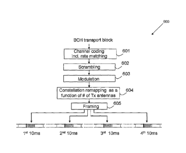
relating to mapping index #11 of Table 3 can be conveyed. Through
this mapping, the configuration of 4 SFBC/FSTD is determined.
[056] FIGURE 8 is an example of a negation mapping. FIGURE 8
is a negation on the I-part after mapping index #1. Through the
negation, the antenna configuration relating to mapping index #17
of Table 3 can be conveyed. Through this mapping, the configuration
of 3 SFBC/FSTD is determined.
[057] FIGURE 9 is another example of a negation mapping. FIGURE
8 is a negation on the Q-part after mapping index #1. Through the
negation, the antenna configuration relating to mapping index #8
of Table 3 can be conveyed. Through this mapping, the configuration
of 3 SFBC/FSTD is determined.
[058] FIGURE 10 is an example of a transport chain 600
illustrating constellation remapping. In the embodiment shown in
FIGURE 10, a channel rate coding including rate matching is preformed
(Block 60i). In addition, the channel rate signal is scrambled (Block
602). Next, the scrambled signal is modulated (Block 603). After
the signal has been modulated, constellation remapping is performed
(Block 604). The remapping of the constellation is done so that
the resulting mapping will convey the antenna configuration of the
- 21 -
CA 02706908 2010-05-26
WO 2009/072789
PCT/KR2008/007108
F200811-0007
base stations 101-103. The constellation remapping is performed
by first identifying the base stations 101-103 antenna configuration.
After the antenna configuration is determined, a mapping that
corresponds to the antenna configuration is selected. Using the
selected mapping configuration, QPSK remapping is preformed to convey
the antenna configuration. Finally, data framing is preformed where
data is placed onto frames for transmission (Block 605) .
[059]It is understood that in the modulation step (Block 603) ,
mapping index #1 in Table 3 is used. After the constellation remapping
step, the overall mapping from the scrambled bits i;(0),...,i)-(Mi,õ -1) to
the output of the constellation remapping step d(0),..., a(Mrsymb -1) can
be described as a mapping in Table 3 whose index is a function f(N,),
where N, is the number of transmission antennas in the base stations
101-103.
[060]In case when there are 3 possible antenna configurations
with 1, 2, or 4 transmit antennas, the modulation step and
constellation remapping step are defined by 3 (out of 24) possible
mappings in Table 3. For example, the following function shows the
mapping that corresponds to the number of antennas in a given
configuration:
- 22 -
CA 02706908 2010-05-26
WO 2009/072789
PCT/KR2008/007108
F200811-0007
{ m #1, N,=1
[061] f(N,)=. m#14, N,=2
m#11, N,=4
[062] Note that the notation m#1 is used to denote the first
mapping in Table 3. The remapping (Block 604) will depend upon the
antenna configuration. For the single transmit antenna configuration
case, the constellation remapping step is simply a(i)=d(i) for 1=0,
Msymb - 1 =
[063] In the case where there are two transmit antennas, as shown
in FIGURE 5, the mapping index #14 of Table 3 can be viewed by applying
a 90 degree shift at the output of the modulation step. For the
sequence at the output of the modulation step, d(0),...,d(Msymb -1) f
d(i).--d/(0+jd0(i) for 1=0,... Msymb -1, and are real and imaginary parts
of d(i) . Then the output of the constellation remapping step gives
a symbol sequence described by:
[064] c-1(i)= j = d(i). jdi(i)- do(i) for =0,... Msymb - 1
[065] As shown in this equation, the 90 degree phase shift simply
translates into an I-Q switch with a negation operation.
[066] In the case that there are four transmit antennas, a -90
degree shift can be applied at the output of the modulation step
on top of mapping #1. For the sequence at the output of the modulation
step d(0),,..,d(Msy,õb -1), if we denote d(i) = dl(i)+ jdo(i) for 1=0, ...
Msymb -1, and
- 23 -
CA 02706908 2010-05-26
WO 2009/072789
PCT/KR2008/007108
F200811-0007
d/(i),cio(i)are denoted as the real and imaginary parts of d(1), then
the output of the constellation remapping step gives a symbol sequence
described by d(i)=-j= AO= -jc 1 1(0+ d 0(i) for 1=0,... Msymb -1 . This -
90
degree phase shift also translates into an I-Q switch with a negation
operation.
[067] For another example of this embodiment, the following
function in the constellation remapping is described:
117 #1, IV, =1
[068] AN,)= m#17, N,=2
1
,n#8, N, = 4
[069] As discussed above for a single transmit antenna the
constellation remapping is d(i)=d(i) for 1=0,... Msy,nb-1.
[070] Where there are two transmit antennas the mapping index
#17 of Table 3 can be viewed by applying a negation operation on
the I-part at the output of the modulation step. For the sequence
at the output of the modulation step d(0),...,d(M,)õ,b-1), if cl(i)=di(i)+
jdQ(i)
for 1=0,... Mb-1, are denoted as the real and imaginary parts of
d(i), then the output of the constellation remapping step gives a
symbol sequence described by cl(i).-d JO+ jdQ(1) for 1=0,... Illsymb ¨1 =
[071] Where there are three transmit antennas, the mapping index
48 of Table 3 can be viewed by applying a negation operation on the
- 24 -
CA 02706908 2010-05-26
WO 2009/072789 PCT/KR2008/007108
F200811-0007
Q-part at the output of the modulation step. For the sequence at
the output of the modulation step d(0),...,c/(111symb -1) f if d (i) = d 1
(i) ,I. d 0 (i)
for i=0,_ Icm,b-1, and c11(),d0(i) denote the real and imaginary parts
of d(i), then the output of the constellation remapping step gives
a symbol sequence described by c7(0=ci1(i)-jci0(i) for i=0,_ Ifv,,,,,-1.
[072] In another embodiment, a mathematical function may be
applied to determine the antenna configuration removing the need
for Table 3. In this embodiment, a mod function may be applied to
an index that results in the configuration of the antenna. In this
example embodiment, the index of the mapping is applied to a modulo
function which results in an integer that corresponds with an antenna
configuration. For example, for the function gOrf,0 as (for i=0,_
Msymb - 1), the following relationships between antenna configuration
and mapping sequences can be determined:
I .
m#1 if mod(i, 3) = 0 /77
#1 if rnod(i, 3) = 0
[ 073]
g(1,0= 1, for all i; g(2, i) = m# 17, if mod(i, 3) = 1 ; g(4, i) = m # 8 if
mod(i ,3) = 1
m # 8, if mod(i, 3) = 2 171#
17, if mod(i, 3) = 2
[074] The modulo function is applied to the constellation index
received by the subscriber station. This removes the need for Table
3, as the modulo result corresponds to the antenna configuration.
- 25 -
CA 02706908 2010-05-26
WO 2009/072789
PCT/KR2008/007108
F200811-0007
[075] For the single antenna configuration, the modulo
constellation remapping is simply a(i)=ci(i) for i=0,... Msymb-1.
[076] For the two transmit antenna modulo configuration, the
length-3 mapping sequence m#1,m#17,m#3 is repeated. For the sequence
at the output of the modulation step d(0),...,d(ilismb -1) f if d(i) = di (0+
i ci Q(i)
for i=0,... Alsym, -1 denotes the real and imaginary parts of d (i) , then
the output of the constellation remapping step gives a symbol sequence
described by:
{d 1 (i) + j d 0 (i), if mod(i,3)=0
[077] (-7(0 = - d 1 (i) + j d 0 (i) , if mod(i,3)=1 , for i=0,... Msymb -1.
di (i)- jd2 (1) , if mod(i,3)=2
[078] For the four transmit antenna modulo configuration, output
of the constellation remapping step gives a symbol sequence described
by:
{d i (i) + j d 0 (1), if mod(i,3)=0
[079] d(i)= el 1 (1)- j ti 0(i), if mod(i,3)=1 for 1=0,,.. illsymb -1.
- d 1 (i) + j d Q (i) , if mod(i,3)=2
[080] FIGURE 11 is a flowchart 700 of the interpretation of
signals by a subscriber station received from base stations 101-103.
In this flowchart, a signal is received by the subscriber station
(Block 701). The subscriber station then collects a sequence of
symbols over the allocated PBCH resource (Block 702). At this point,
- 26 -
CA 02706908 2010-05-26
WO 2009/072789
PCT/KR2008/007108
F200811-0007
the constellation is interpreted to determine the proper number of
antennas. It is understood that inmost cases this will be sufficient
to determine the antenna configuration. This configuration can be
confirmed using the following three assumptions. It is understood
that the first assumption chosen will be based upon constellation
information, and a second assumption will be used only if the first
assumption fails to result in a true CRC check. A "true" CRC check
refers to a CRC operation where no error appears, and a "false" CRC
check refers to a CRC operation where an error appears.
[081] In the first assumption, there is an inverse constellation
remapping step assuming a 1 transit antenna configuration (Block
703) . The output from the remapping step is then demodulated assuming
a single transmitter (Block 704). Next, descrambling and decoding
are performed on the data (Block 705). Finally, a CRC check is
performed on the decoded data. (Block 707). If the CRC check passes,
and the data is not corrupt, then the assumption that there is one
transmit antenna is confirmed.
[082] In the second assumption, there is an inverse constellation
remapping step assuming a two transit antenna configuration (Block
709) . The output from the remapping step is then demodulated assuming
two transmitters using an SFBC receiver (Block 710). Next,
descrambling and decoding are performed on the data (Block 711).
- 27 -
CA 02706908 2010-05-26
WO 2009/072789
PCT/KR2008/007108
F200811-0007
Finally, a CRC check is performed on the decoded data (Block 712).
If the CRC check passes, and the data is not corrupt, then the
assumption that there are two transmit antennas is confirmed.
[083] In a third assumption, there is an inverse constellation
remapping step assuming a four transit antenna configuration (Block
713) . The output from the remapping step is then demodulated assuming
four transmitters using an SFBC/FSTD receiver (Block 714). Next,
descrambling and decoding are performed on the data (Block 715).
Finally, a CRC check is performed on the decoded data (Block 716).
If the CRC check passes, and the data is not corrupt, then the
assumption that there are four transmit antennas is confirmed.
[084] In each of Blocks 706, 711, and 715 four separate decodes
are preformed. These decodes are preformed at the timings 10, 20,
30, and 40 ms. Therefore, while the configuration of the antennas
in the base stations 101-103 can be determined, the timing may not
be determined. The time is confirmed by testing the decodes at each
timing against the CRC check. When the result of the CRC check is
true, the timing and antenna configuration is confirmed.
(0851 After one of the assumptions is confirmed, the number of
transmit antennas is known (Block 708). This information along with
the correct timing is used to interpret the PBCH content. It is
understood that the constellation remapping as a function of number
- 28 -
CA 02706908 2010-05-26
WO 2009/072789
PCT/KR2008/007108
F200811-0007
of transmit antennas can be applied to other physical channel, and
to other modulations such as BPSK, 16QAM and 64QAM, etc.
[086] In another embodiment of the present disclosure, a CRC
masking step is added to the PBCH transport block. The resulting
transmission chain 800 is shown in FIGURE 12. The CRC masking means
the CRC bits are masked by a bit sequence that is a function of the
number of transmit antennas.
[087] FIGURE 12 shows that data is input into the system (Block
801). A CRC mask is applied to the data entering into the system
(Block 802). The data is then scrambled (Block 803) and modulated
(Block 804). Premapping, as discussed in the previous embodiment,
may optionally be added. (Block 805). Finally, the data is placed
onto data frames (Block 806).
[088] FIGURE 13 is an example 900 of how the CRC mask may be
applied. A P-BCH payload is received for transmission (Block 901).
Based on the data, a CRC code is generated (Block 902). This CRC
code is then masked by a sequence that is a function of the number
of transmit antennas (Block 903).
[089] A CRC check is usually performed on data to ensure the
reliability and integrity of the data. There
are many ways of
calculating a CRC code and implementing a CRC check. For example,
a CRC may be polynomial of x^4+x+1. This can be used to check to
- 29 -
CA 02706908 2010-05-26
WO 2009/072789
PCT/KR2008/007108
F200811-0007
see that the data is intact. This polynomial can be applied to any
data consistent with the CRC-4 standard. Take for instance the
following input data:
[090] 00000001 (data)
[091] If sent and received over a known communications channel,
and this data remains intact. The following function illustrates
that the CRC of this data would return a true result.
[092] CRC(000000001) = true
[093] However, with the present invention, the data is masked
with another CRC mask. Therefore, the data goes through the following
transformation:
[094] 00000001 (data) 4 00000002 (masked data)
[095] Using the old CRC check, the result would be false.
[096] CRC(000000002) = False
[097]The present disclosure uses a plurality of masks to alter
data. These masks are then checked against the CRC check to determine
which is true. For instance, using the data 000000001, the following
masks could be used:
[098]00000001 (data) 4 00000002 (masked data, one antenna)
[099]00000001 (data) 00000003 (masked data, two antennas)
[0100] 00000001 (data) --) 00000004 (masked data, four antennas)
- 30 -
CA 02706908 2010-05-26
WO 2009/072789
PCT/KR2008/007108
F200811-0007
[0101] The masked data, when received by the subscriber station,
goes through an inverse process of demasking. If the masked data
is demasked by the "right" mask, then the CRC check will be true.
For instance, 00000003 demasked with the one antenna mask would
not equal 00000001, and therefore the CRC check would fail. The
00000003 demasked with the two antenna mask would equal 00000001,
and therefore the CRC check would succeed. In this way, the data
transmitted to a subscriber station can be masked with information
relating to the antenna configuration of the base stations 101-103.
[0102] Returning to FIGURE 13, the P-BCH is concatenated with
the masked CRC (Block 904). In this block, the data is combined
with the masked CRC allowing the data to be appropriately interpreted
by the subscriber station.
[0103] FIGURE 14 is a flowchart 1000 of the interpretation of
signals by a subscriber station received from base stations 101-103.
In this flowchart, a signal is received by the subscriber station
(Block 1001). The subscriber station then collects a sequence of
symbols over the allocated PBCH resource (Block 1002). At this point,
three assumptions are made as to the antenna configuration. One
of the three should result in a true result, and the true result
will correspond to the correct antenna configuration. Unlike the
embodiment that encodes the antenna configuration into the QSPK
- 31 -
CA 02706908 2010-05-26
WO 2009/072789
PCT/KR2008/007108
F200811-0007
constellation, the CRC embodiment does not give information directly
relating to the antenna configuration. Therefore, unlike the QSPK
constellation embodiment, each assumption may be tried.
[0104] In a first assumption, there an inverse constellation
remapping step assuming a 1 transit antenna configuration (Block
1003). The
output from the remapping step is then demodulated
assuming a single transmitter (Block 1004). Next, descrambling and
decoding are performed on the data (Block 1005). Finally, a CRC
check is performed on the decoded data using a first CRC mask. (Block
1006). If the CRC check passes, then the assumption that there is
one transmit antenna is confirmed.
[0105] In a second assumption, there is an inverse constellation
remapping step assuming a two transit antenna configuration (Block
1009). The
output from the remapping step is then demodulated
assuming two transmitters using an SFBC receiver (Block 1010). Next,
descrambling and decoding are performed on the data (Block 1011).
Finally, a CRC check is performed on the decoded data using a second
CRC mask (Block 1012). If the CRC check passes, then the assumption
that there are two transmit antennas is confirmed.
[0106] In a third assumption, there is an inverse constellation
remapping step assuming a four transit antenna configuration (Block
1013). The
output from the remapping step is then demodulated
- 32 -
CA 02706908 2010-05-26
WO 2009/072789
PCT/KR2008/007108
F200811-0007
assuming four transmitters using an SFBC/FSTD receiver (Block 1014).
Next, descrambling and decoding are performed on the data (Block
1015). Finally, a CRC check is performed on the decoded data using
a third CRC mask (Block 1016). If the CRC check passes, then the
assumption that there are four transmit antennas is confirmed.
[0107] In each of Blocks 1005, 1011, and 1015, four separate
decodes are performed. These decodes are performed at the timings
10, 20, 30, and 40 ms. Therefore, while there are three assumptions
being made about the number of antennas in the base stations 101-103,
each one of these configurations may have four timings. Therefore,
there are actually twelve tests performed to determine the correct
configuration of base stations 101-103.
[0108] After one of the assumptions is confirmed, the number of
transmit antennas is known. This information along with the correct
timing is used to interpret the PBCH content (Block 1007).
[0109] It is understood that both the QPSK constellation and error
correcting codes may be used in a single embodiment. FIGURE 15 is
an example embodiment 1100 where both QPSK constellation mapping
and CRC masking are used. Data is input into the system (Block 1101).
A CRC mask is applied to the data entering into the system (Block
1102). The data is then scrambled (Block 1103) and modulated (Block
- 33 -
CA 02706908 2010-05-26
WO 2009/072789
PCT/KR2008/007108
F200811-0007
1104). The
antenna configuration is then mapped onto the QPSK
constellation, and the data is placed onto data frames (Block 1105).
[0110] FIGURE 16 is a flowchart 1200 of the interpretation of
signals by a subscriber station received from base stations 101-103
using both a QPSK constellation and a CRC mask. In this flowchart,
a signal is received by the subscriber station (Block 1201). The
subscriber station then collects a sequence of symbols over the
allocated PBCH resource (Block 1202). This information is used to
determine the antenna configuration of the base stations 101-103
through the QPSK constellation. Three assumptions can be used to
confirm the antenna configuration obtained from the QPSK
constellation.
[0111] In a first assumption, there is an inverse constellation
remapping step assuming a 1 transit antenna configuration (Block
1203). The output from the remapping step is then demodulated
assuming a single transmitter (Block 1204). Next, descrambling and
decoding are performed on the data (Block 1205). Finally, a CRC
check is performed on the decoded data using a first CRC mask (Block
1206). If the CRC check passes, then the assumption that there is
one transmit antenna is confirmed.
[0112] In a second assumption, there is an inverse constellation
remapping step assuming a two transit antenna configuration (Block
- 34 -
CA 02706908 2010-05-26
WO 2009/072789
PCT/KR2008/007108
F200811-0007
1208). The
output from the remapping step is then demodulated
assuming two transmitters using an SFBC receiver (Block 1209). Next,
descrambling and decoding are performed on the data (Block 1210).
Finally, a CRC check is performed on the decoded data using a second
CRC mask (Block 1211). If the CRC check passes, then the assumption
that there are two transmit antennas is confirmed.
[0113] In a third assumption, there is an inverse constellation
remapping step assuming a four transit antenna configuration (Block
1212). The
output from the remapping step is then demodulated
assuming four transmitters using an SFBC/FSTD receiver (Block 1213).
Next, descrambling and decoding are performed on the data (Block
1214). Finally, a CRC check is performed on the decoded data using
a third CRC mask (Block 1215). If the CRC check passes, then the
assumption that there are four transmit antennas is confirmed.
[0114] In each of Blocks 1205, 1210, and 1214, four separate
decodes are performed. These decodes are performed at the timings
10, 20, 30, and 40 ms. Therefore, while there are three assumptions
being made about the number of antennas in the base stations 101-103,
each one of these configurations may have four timings. Therefore,
there are actually twelve tests performed to determine the correct
configuration of base stations 101-103.
- 35 -
CA 02706908 2010-05-26
WO 2009/072789
PCT/KR2008/007108
F200811-0007
[0115] After one of the assumptions is confirmed, the number of
transmit antennas is known. This information along with the correct
timing is used to interpret the PBCH content (Block 1207).
[0116] Through the use of both QPSK constellations and CRC masks,
the antenna configuration of the base stations 101-103 can be
confirmed.
[0117] Although the present disclosure has been described with
an exemplary embodiment, various changes and modifications may be
suggested to one skilled in the art. It is intended that the present
disclosure encompass such changes and modifications as fall within
the scope of the appended claims.
- 36 -