Language selection

Search

Patent 2706989 Summary

Third-party information liability

Some of the information on this Web page has been provided by external sources. The Government of Canada is not responsible for the accuracy, reliability or currency of the information supplied by external sources. Users wishing to rely upon this information should consult directly with the source of the information. Content provided by external sources is not subject to official languages, privacy and accessibility requirements.

Claims and Abstract availability

Any discrepancies in the text and image of the Claims and Abstract are due to differing posting times. Text of the Claims and Abstract are posted:

  • At the time the application is open to public inspection;
  • At the time of issue of the patent (grant).
(12) Patent: (11) CA 2706989
(54) English Title: CLAMP WITH ADJUSTABLE LENGTH ROD
(54) French Title: BRIDE TELESCOPIQUE
Status: Deemed expired
Bibliographic Data
Abstracts

English Abstract


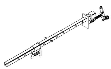
A clamp with adjustable length rod is designed to fastening short
or long work pieces with the same tool.
The clamp, which is the object of present application, is composed
of two rectangular pipes: A and B as is shown in drawings - Fig-4
and 5, the exterior one (B) sliding along the interior one (A).
The proposed invention eliminates the need of long clamps and the
inconveniences resulting from using a too long clamp for holding
short work pieces, by adjusting the clamp length to the length of
the work piece.
The adjustable length rod clamp is intended for the use of anybody
who needs to fasten either short and long work pieces - mainly
woodworkers.


French Abstract

Une bride télescopique est conçue pour fixer des pièces à travailler longues ou courtes avec le même outil. La bride, qui est le sujet de la présente application, est composée de deux tuyaux rectangulaires : A et B, comme l'indiquent les dessins - Fig-4 et 5, le tuyau extérieur (B) glissant le long du tuyau intérieur (A). L'invention proposée élimine le besoin de longues brides et les incommodités entraînées par l'utilisation d'une trop longue bride pour assujettir des pièces à travailler courtes, en ajustant la longueur de la bride en fonction de la longueur de la pièce à travailler. La bride télescopique est conçue pour être utilisée par quiconque doit travailler avec des pièces à travailler longues ou courtes, principalement les travailleurs du bois.

Claims

Note: Claims are shown in the official language in which they were submitted.


What is claimed:


1. A clamp with adjustable length rod composed of two pipes:
first pipe carries a jaw secured at its end, the second pipe
which has the interior section slightly larger than the first
one's exterior in order to slide along it, carries a movably
securable jaw in position opposite to fixed jaw.

2. The clamp of claim #1 where the pipes have a square or
rectangular section.

3. The clamp of claim #1 where the pipes have holes driven on
their flanks at the same distance and the same alignment, as
a pin can be inserted trough both pipes holes in order to
secure them together.

4. The clamp of claim #1 where the distance between holes is
in accordance with the length of the fixed jaw's tread in
order to permit an accurate position for holding work
pieces.


-3-

Description

Note: Descriptions are shown in the official language in which they were submitted.


CA 02706989 2012-09-04

CLAMP WITH ADJUSTABLE LENGTH ROD
DESCRIPTION

Technical field:

This invention relates to clamps used by woodworkers and other
craftsmen as well as by the do-it-yourself enthusiasts.
Bar or pipe clamps are widely used by all of these categories.
They all have the same problem; for large work pieces, they need
long clamps. A long clamp can be used also for short pieces, but
with all inconveniences derived. In order to cover all situations,
they need a large number of clamps, which means money and storage
space.

Background of the invention:

The problem is not new, as other inventors tried to solve it;
SPRINGER, SCOTT D. (US 007322571, CA 2589417) or PERT, JAMS (UK
2104586).
Although both of these inventions solve the problem of large work
pieces, they are limited by employing two clamps (Springer) or by
the cost of manufacturing (Pert).

Summary of the invention:

The object of present invention is to provide a clamp with
adjustable length rod, which can be used for short or long pieces
either and which is also easy and inexpensive to be manufactured.
The "adjustable length rod" of the present invention, consists
in two square pipes - the interior dimensions of one of them (5-
Fig. 4, 5) being slightly larger than other's exterior (A-Fig.4,5)
in order to slide along it.
By moving the exterior pipe along the interior one and secure
them by mean of a pin, the length of the clamp can be chosen in
accordance with the length of the work piece.

Description of the drawings:

F2g.I depicts a perspective view of a traditional pipe clamp,
available at any store. It appears clear that the length of pipe
limits the length of work piece to be held.

Ilit.2 is a perspective view of the present invention.

F..g.3 illustrates the advantages of the proposed invention. It is
a perspective view of two possible utilisation of it.

Fig.d is a detailed perspective of the proposed invention. it
appears clear the first pipe - A which carries the fixed jaw - Al,


CA 02706989 2012-09-04

the second pipe - S carrying the movable jaw - Bi, and the pin C
inserted trough both pipe holes.

rig.5 represents in perspective the two component pipes of the
proposed invention, the respective jaws, and the pin.
Description of the preferred embodiment:

The proposed invention, as its inventor intends it, consists of
two square pipes. That shape will prevent the exterior pipe to
rotate and impending the worker to easily insert the pin trough
both pipe holes.
First pipe (A-Fig. 4,5), which carries a fixed jaw (Al-Fig.
4,5), has holes drilled on its flanks at the same alignment and
distance.
The second pipe (B-Fig. 4,5) has the interior dimensions
slightly larger than the first one's exterior, in order to slide
along it and has holes at the same alignment with the holes of
first pipe. That second pipe carries a second, movable, jaw (81-
Fig.4, 5) securable along it and opposite to the fixed jaw of the
first pipe.
A pin (C, Fig.4, 5) is inserted through both pipes holes, in
order to secure them together.
The use of this new kind of clamp is very simple, being somewhat
similar with the use of traditional clamp.
After positioning the clamp, and the fixed jaw (Al) at the
desired point of work piece, the exterior pipe (B) slides along
the interior one's at the best position, until the holes of two
pipes are aligned (operation made easy by the fact that the
distance from the ends of exterior pipe and its holes is equal
with the distance between the interior pipe's holes) and the
movable jaw B1 (which mirrored the fixed jaw-Al, in order to hold
the work piece) is secured in place, the pin C is inserted trough
both pipes holes in order to secure them together.
Then, the screw of the fixed jaw Al will squeeze the work piece.
By coupling more than two pipes will be possible to arrive at any
desiderate length.

Representative Drawing
A single figure which represents the drawing illustrating the invention.
Administrative Status

For a clearer understanding of the status of the application/patent presented on this page, the site Disclaimer , as well as the definitions for Patent , Administrative Status , Maintenance Fee  and Payment History  should be consulted.

Administrative Status

Title Date
Forecasted Issue Date 2013-02-05
(22) Filed 2010-06-14
Examination Requested 2010-11-18
(41) Open to Public Inspection 2011-12-14
(45) Issued 2013-02-05
Deemed Expired 2017-06-14

Abandonment History

There is no abandonment history.

Payment History

Fee Type Anniversary Year Due Date Amount Paid Paid Date
Application Fee $200.00 2010-06-14
Request for Examination $400.00 2010-11-18
Maintenance Fee - Application - New Act 2 2012-06-14 $50.00 2012-05-22
Final Fee $150.00 2012-11-15
Maintenance Fee - Patent - New Act 3 2013-06-14 $50.00 2013-06-10
Maintenance Fee - Patent - New Act 4 2014-06-16 $50.00 2014-04-08
Maintenance Fee - Patent - New Act 5 2015-06-15 $100.00 2015-06-11
Owners on Record

Note: Records showing the ownership history in alphabetical order.

Current Owners on Record
POPESCU, GABRIEL
Past Owners on Record
None
Past Owners that do not appear in the "Owners on Record" listing will appear in other documentation within the application.
Documents

To view selected files, please enter reCAPTCHA code :


To view images, click a link in the Document Description column. To download the documents, select one or more checkboxes in the first column and then click the "Download Selected in PDF format (Zip Archive)" or the "Download Selected as Single PDF" button.

List of published and non-published patent-specific documents on the CPD .

If you have any difficulty accessing content, you can call the Client Service Centre at 1-866-997-1936 or send them an e-mail at CIPO Client Service Centre.


Document
Description 
Date
(yyyy-mm-dd) 
Number of pages   Size of Image (KB) 
Abstract 2010-06-14 1 22
Description 2010-06-14 3 115
Drawings 2010-06-14 5 91
Claims 2010-06-14 1 40
Representative Drawing 2011-10-21 1 8
Abstract 2012-08-09 1 17
Description 2012-08-09 3 112
Cover Page 2011-12-05 1 31
Cover Page 2013-01-17 1 35
Description 2012-09-04 2 96
Claims 2012-09-04 1 20
Assignment 2010-06-14 4 345
Correspondence 2010-07-19 1 14
Prosecution-Amendment 2011-03-15 1 24
Prosecution-Amendment 2010-11-18 1 17
Prosecution-Amendment 2012-08-09 6 174
Prosecution-Amendment 2012-05-22 6 252
Fees 2012-05-22 1 130
Prosecution-Amendment 2012-08-23 2 51
Prosecution-Amendment 2012-09-04 5 158
Correspondence 2012-11-15 1 68
Fees 2014-04-08 1 121
Fees 2013-06-10 1 21
Maintenance Fee Payment 2015-06-11 1 62
Correspondence 2015-08-24 1 22