Note: Descriptions are shown in the official language in which they were submitted.
CA 02707224 2010-06-10
- 1 -
SNOW REMOVAL VEHICLE
TECHNICAL FIELD
[0001] The present invention relates to a snow removal
road vehicle using high pressure steam jets to melt the snow
inside an enclosed snow melting chamber of the vehicle.
BACKGROUND ART
[0002] Snow removal vehicles or containers are known
wherein snow is collected and dumped into a container which
is provided with conduits through which hot gases flow and
which are located close to a top end of these containers
whereby snow positioned thereon will melt and the water
accumulate at the bottom of the container. Baffle plates
are provided so that only water can percolate down into the
reservoir. A disadvantage of these is that the reservoirs
are not displaceable and they are usually positioned in
areas where large parking areas need to be maintained clear
of snow. Snow removal vehicles with articulated buckets are
required to transport the snow to the container. The
container usually has a conduit which connects to the city
sewer system to discharge water therefrom.
[0003] With reference to U.S. Patent Nos. 4,785,561 and
5,588,231, it is also known to provide such containers on
vehicles whereby to remove snow from streets and blow the
snow into a container which contains boiler tubes. The
boiler tubes, as shown in U.S. Patent 4,785,561 melt the
snow and water is evacuated from the vehicle. However, such
snow melting systems have not been found satisfactory as
they are too small and the conduit will clog up with snow
rendering the vehicle's function ineffective. For snow
removal applications on streets, such a vehicle is not
practical. Also, there are insufficient heating means to
melt the snow faster than it is discharged within the
CA 02707224 2010-06-10
2 -
chamber. U.S. Patent 5,588,231 describes a similar system
although the vehicle is much larger. It is also provided
with a boiler and a heater pipe system to circulate hot
water therein. A snow blower is used to feed snow into a
feeder chute which is of very long length and which
obviously would clog up with snow rendering the entire
vehicle ineffective. This system is deemed to be inoperable
because of its many deficiencies. Further, the melting
hopper is too small and would prevent the vehicle from
operating at convenient speeds.
SUMMARY OF INVENTION
[0004] It is a feature of the present invention to
provide a snow removal vehicle which utilizes high pressure
steam in an enclosed snow melting chamber of the vehicle to
melt snow and wherein the water produced by the melted snow
and condensed steam is collected in the snow melting
chamber.
[0005] Another feature of the present invention is to
provide a snow removal vehicle having an adjustable front
entry opening to adjust the width of the path of the snow
being removed from roads and wherein the snow is melted by
contact with high pressure steam in an enclosed snow melting
chamber of the vehicle, and the collected water in the
chamber is drained therefrom into the public sewer system
once the water collecting reservoir of the vehicle reaches a
predetermined quantity.
[0006] Another feature of the present invention is to
provide a snow removal vehicle which utilizes a single
operator for its operation and reduces the amount of
equipment normally required to clear snow from roads.
(0007] According to another feature of the present
invention there is provided a snow removal vehicle wherein a
hopper shute is removably securable to a frontal entry
CA 02707224 2010-06-10
- 3 -
opening of the vehicle for guiding snow introduced from an
open top end of the hopper shute to an auger screw
permitting the vehicle to be used as a snow melting and
transport vehicle.
[0008] According to the above features, from a broad
aspect, the present invention provides a snow removal
vehicle comprising a vehicle body having an enclosed snow
melting chamber. The vehicle body is supported on traction
means. An operator station is provided for an operator
person. The vehicle body has an entry opening communicating
with the snow melting chamber. Snow removal means is
provided in the entry opening to eject snow inside a forward
end of the snow melting chamber. The snow melting chamber
has a water collecting reservoir in a lower portion thereof
below a bottom wall of the snow melting chamber. Passage
means are provided in the bottom wall to channel water from
the snow melting chamber to the water collecting reservoir.
A plurality of high pressure steam snow melting jets are
disposed along the snow melting chamber to eject hot steam
therealong. Snow propelling means is provided along at
least a front end portion of the snow melting chamber to
propel snow ejected from the snow removal means in the entry
opening along the snow melting chamber for contact by the
steam to melt the snow. Water evacuating means is provided
to evacuate water collected in the water collecting
reservoir.
BRIEF DESCRIPTION OF THE DRAWINGS
[0009] A preferred embodiment of the present invention
will now be described with reference to the accompanying
drawings in which:
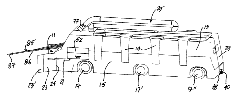
[00010] FIG. 1 is a perspective view of the snow
removal vehicle of the present invention;
CA 02707224 2010-06-10
4 -
[00011] FIG. 2 is a perspective transverse section view
of the snow removal vehicle of the present invention;
[00012] FIG. 3 is an enlarged fragmented cross-
sectional side view of the snow melting chamber;
[00013] FIG. 4 is a fragmented cross-section view
illustrating the position of the steam jets relative to a
snow propelling wheel of the snow melting chamber;
[00014] FIG. 5A is a side view of a high pressure steam
snow melting jet;
[00015] FIG. 5B is a top view of Figure 5A;
[00016] FIG. 5C is a cross-section view along cross-
section line C-C of Figure 5A;
[00017] FIG.6A is a side view of a further embodiment
of a high pressure snow melting jet;
[00018] FIG. 6B is a section view along cross-section
line B-B of Figure 6A;
[00019] FIG. 7 is a block diagram illustrating the
function of the control panel in association with various
elements of the snow removal vehicle;
[00020] FIG. 8 is a transverse section view through the
vehicle showing the construction of the ice removal steel
brush;
[00021] FIG. 9 is a transverse section view through the
vehicle showing the displaceable axle;
[00022] FIG. 10 is a simplified schematic side view
showing a hopper shute removably securable to the front
entry opening of the snow removal vehicle;
[00023] FIG. 11A is a perspective view of the hopper
shute;
[00024] FIG. 11B is a top view of the hopper shute; and
[00025] FIG. 11C is a side view showing the hopper shute
removably connected to the hinge plow side panels.
DESCRIPTION OF PREFERRED EMBODIMENTS
CA 02707224 2010-06-10
-
[00026] Referring to the drawings and more particularly to
Figures 1 and 2, there is shown generally at 10 the snow
removal vehicle of the present invention. As shown in
Figures 1 and 2, the front end of the vehicle has a front
entry opening 11 in which an auger means in the form of an
auger screw 12 is mounted and driven at high speed whereby
to eject snow positioned thereagainst rearwardly into the
vehicle body 13. A plurality of steam generators 14 are
mounted integral with the side walls 15 of the vehicle body
13. The vehicle body 13 defines therein an enclosed snow
melting chamber 16 as shown in Figure 2 and it communicates
with the front entry opening 11. The vehicle body is also
insulated. The vehicle 10 is supported on three sets of
wheels 17, 17' and 17", but could also be supported on
tracks or other propelling means, not shown.
[00027] As shown in Figure 2, the front entry opening 11
is provided with a snow guiding ramp 18 rearwardly of the
snow auger screw 12 whereby to guide projected snow in an
upward direction of arrow 19 upwardly into the forward end
20 of the snow melting chamber 16.
[00028] The front entry opening 11 is further provided
with variable snow collecting means in the form of hinged
plow side panels 23, as better shown in Figures 1 and 2
which are secured to opposed side edges 24 of the front
entry opening 11. The panels 23 may be equipped with a
telescopic frontal section 23' to adjust the length of the
panels. Pistons 21 are secured to each of these panels
whereby to position the hinge plow panels 23 at a desired
angle with respect to the front entry opening. Each panel
23 is independently controlled. By controlling the position
of the angle of these side panels an operator person can
control the width of a surface to be plowed, or in this case
to clear the snow therefrom as the snow is not displaced to
the sides but is ingested by the snow removal vehicle 10.
CA 02707224 2010-06-10
6 -
[00029] With specific reference now to Figures 2 and 3,
the enclosed snow melting chamber 16 has an intermediate
bottom wall 25 supported elevated from the bottom wall 26 of
the vehicle. The area between the bottom wall 25 of the
chamber and the bottom wall 26 of the vehicle defines a
water collecting reservoir 27. A plurality of high-pressure
snow melting, high pressure steam turbo-jets 28 are
positioned within the vehicle opposed side walls 15. As
shown in Figure 4, these jets may also be optionally mounted
in the top wall 29 and adjacent the bottom wall 25 and these
are identified by reference numeral 28'. These high-
pressure snow melting jets are connected to suitable conduit
means (not shown) to the steam generators 14 whereby the
enclosed snow melting chamber 16 is filled with high-
pressure steam turbulence of about 25 thousand BTUs, along
its entire length or at least concentrated in the front
portion thereof. Jets 28" may also be fitted with snow
propelling wheels 32. Cameras 30 are also mounted in the
enclosed snow melting chamber 16 to provide visual access
thereof from the control cabin 31 at the front end of the
vehicle where an operator sits and controls the vehicle. A
control panel 32 is provided in the conductor cabin 31.
[00030] A plurality of snow propelling means in the form
of propelling wheels 32 are secured in the enclosed snow
melting chamber 16 along at least the forward end portion 20
thereof to propel snow ejected from the auger screw 12 along
the snow melting chamber and in contact with the high
pressure steam from the high pressure steam ejecting jets 28
whereby to disperse the snow for contact with the high-
pressure hot steam to melt the snow quickly. Water
resulting from the melted snow and condensed steam is
channeled within the water collecting reservoir 27 through
openings 35 formed in the bottom wall 25 of the snow melting
chamber 16. These passage openings 35 have a trough-like
CA 02707224 2010-06-10
7 -
shaped wall section 36 and a sufficient number of these are
provided whereby the water is evacuated quickly from the
snow melting chamber to flow to the water collecting
reservoir. Two or more level sensors 37, see Figure 3, are
secured in a wall of the water collecting reservoir to
detect the water level. A second uppermost one of the
sensors, namely sensor 37', would advise the operator of an
approximate quantity of snow that needs to be collected
until a top sensor 37" gives a signal to the operator that
the reservoir needs to be emptied. This permits the
operator to gauge the time remaining to evacuate the water
from the reservoir.
[00031] In order to evacuate the water from the reservoir
27 there is provided a drain pipe 38, hereinshown mounted in
the rear wall 39 of the vehicle and it has a valve 40. A
flexible conduit (not shown) is connected to the drain pipe
38 whereby to channel the water from the water collecting
reservoir into the city sewer system or elsewhere. Although
not shown, one of the steam generators 14 may have another
flexible hose connected thereto together with a mechanical
rod having a control valve whereby to unblock a city sewer
should a sewer be iced-in whereby the reservoir can be empty
under any cold climate condition in the sewer system. The
location of city sewers would also be accessible through
stored information available in the control panel.
[00032] As more clearly illustrated in Figures 2 and 3,
the propelling wheels 32 have a driven axle 45 which is
supported across the opposed side walls 15 of the vehicle
across the snow melting chamber 16 and this is done by
conventional mechanical means. The snow propelling wheels
32 are also supported elevated above the bottom wall 25. To
each of the axles 45 there is secured a drum 45' having at
least two, herein a plurality of elongated flat blades 46
and extending along opposed sides of the drum and projecting
CA 02707224 2010-06-10
- 8 -
outwardly therefrom. The blades 46, when seen in cross-
section, have an elongated curved profile 47 which slopes in
the direction of the blade, herein in the clockwise
direction as indicated by arrow 48 to project snow disposed
on a collection surface 49 thereof upwardly and in a
rearward direction, as shown by arrows 48', within the snow
melting chamber 16 for contact with the high-pressure steam
being ejected by the jets 28. The axles 45 may have a
sprocket adjacent an end thereof and driven by a drive chain
which is secured to an electric motor whereby to drive these
propelling wheels in a clockwise direction. Accordingly,
snow from the auger is fed inwardly into the first
propelling wheel 32' and it ejects snow upwardly in the
direction of arrows 50 for contact with the hot steam. Any
snow that has not melted is then deposited onto the
following snow propelling wheel 32 and so on until there is
no snow, or very little snow, within the enclosed snow
melting chamber. Any snow falling on the bottom wall 25
will melt quickly due to the heat generated by hot water
collected within the chamber 16 and the jets.
Alternatively, the bottom wall 25 can be heated by running
the conduits (not shown) from the steam generators 14 in
contact under the wall 25.
[00033] It is also pointed out that the snow melting jets
28 may be connected in two or more groups along the snow
melting chamber 16. Each group of snow melting jets may be
secured to one or more steam generators 14. Each steam
generator of each of the groups of jets is controlled
through the control panel 32 in the cabin 31. This is
accomplished, as shown in Figure 7, by controlling valves 51
associated with each steam generator 14. As shown in Figure
4, the drum 45' of the propelling wheels 32 may also be
equipped with jets 28".
CA 02707224 2010-06-10
- 9 -
[00034] Referring now to Figures 5A to 6B, there will be
described the construction of two types of the snow melting
jets 28. As shown in Figures 5A to 5C, a first type of the
snow melting jets is identified by reference numeral 60 and
it has an outer conical shape 61 whereby to form a pressure
build-up formation 62 on its inner conical passage 61'. As
shown in Figures 5B and 5C, flanges 63 having an arcuate
shape project inside the conical passage 61' and these are
of reduced size and create resistance to the high pressure
steam line connected to the connector end 64 of the jet 60.
This progressively diminishing passage extends to an open
nozzle end 65 where the hot steam is ejected at an increased
pressure of about 20,000 to 30,000 psi and in the form of a
beam.
[00035] In the embodiment of Figures 6A and 6B, the high
pressure steam snow melting jet 70 is differently shaped and
it has a pressure build-up section 71 of reduced cross-
section as hereinshown whereby pressure from the conduit
connected at its connecting end 72 will build-up and be
directed through a narrow bottom opening 73 into a flared
narrow passage created in the flared section 74 providing a
wide flat beam of high pressure steam whereas in the
embodiment of Figures 5A to 5C the hot steam is ejected as a
very narrow thin-shaped beam. These types of nozzles are
directionally mounted to permit the construction of a snow
melting chamber producing hot steam beams which are of a
flared profile and beam-shaped profile and oriented such as
to prevent the accumulation of snow within the snow melting
chamber.
[00036] As shown in Figure 7, the control panel also
controls motors 52 coupled to the axles of each of the snow
propelling wheels 32 and these can also be controlled
independently, as will be described later. As shown in
Figure 1, a control panel 52 may also be mounted exteriorly
CA 02707224 2010-06-10
- 10 -
of the vehicle body 13 to monitor part of the system such as
to provide a signal to the operator that the water
collecting reservoir 27 is empty as the operator is outside
the vehicle to evacuate collected water into the city sewer
system. Of course, this can also be sensed or made visible
by a transparent section of the conduit connected to the
pipe 38 when water stops flowing. A submersible pump, not
shown, may also be mounted in the water-collecting reservoir
27 to evacuate water therefrom at high speed whereby the
vehicle does not remain idle for a long period of time to
discharge the water collected in the reservoir. A GPS
system may also be integrated with the control panel to
indicate a route for the operator of the vehicle and the
status of the streets on which snow has to be collected or
has already been cleared.
[00037] Figures 1 and 2 show an articulated boom 75 formed
of rigid vacuum conduit sections 76 and a rectangular
suction port 77 to suck snow from side walls, roofs and
other areas difficult to access. The boom 77 connects to an
impeller chamber 78 inside the vehicle where a discharge
wheel 79 releases the snow onto a propelling wheel 32
through an opening 80. The impeller wheel 79 is driven at
high speed to create a suction air flow in the articulated
conduit 75 and direct snow thereon to be propelled through
the opening 80 at the end of the curved side wall section
81.
[00038] As shown in Figures 1 and 2, it can be seen that
the snow removal vehicle 10 of the present invention is
further provided with a metal detector assembly 85 which is
comprised of a boom 86 having a metal detector sensor 87
secured to a free forward end thereto. The support frame 86
projects forwardly of the vehicle to detect metal objects in
the snow in the path of the vehicle. This metal detector 87
provides signals to the control panel 32 in the operator
CA 02707224 2010-06-10
- 11 -
station 31 whereby to alarm the operator of a metal object
in its path to be removed.
[00039] As shown in Figures 2 and 8, also provided with
the snow removal vehicle of the present invention is an
operator actuable ice abrading and removal steel brush 90
which is secured rearwardly of the auger wheel 12 to abrade
and brake ice formed on the road surface where snow is being
removed. The brush is lowered and retracted by a pair of
cylinders 92 secured at opposed ends of the brush axle 93.
The abraded and broken ice is propelled by the high speed
rotating brush 19 into the snow propelling wheel 32 through
a trap door 91 which can also be operated from the cabin.
The door 91 also forms a protective passage when open, not
shown, to prevent water from the melted snow in the snow
melting housing from leaking out therethrough. The brush 90
is a steel brush having stiff bristles capable of abrading
and cutting ice.
[00040] With reference to Figures 1 and 9, it is pointed
out that there are three sets of traction wheels, namely
traction wheels 17, 17' and 17". The front and rear sets 17
and 17" are driven in tandem whereas the intermediate set is
independently driven. The intermediate set of wheels 17' is
also supported elevated from the front and rear sets 17 and
17" by cylinders 95 and is provided with a disconnectable
drive coupling, of a type well known in the art. The
intermediate set 17' has a displaceable axle 94 to which the
cylinders 95 are secured whereby this set can be lowered to
engage the ground surface and be connected to a drive shaft
by its drive coupling to permit independent operation of the
wheels of the intermediate set whereby to cause the vehicle
to maneuver around abrupt street intersections by the use of
the intermediate set of wheels.
[000411 Referring now to Figure 10, there is shown a
fragmented front view of the vehicle and to which is
CA 02707224 2010-06-10
- 12 -
removably secured a hopper shute 80 whereby snow can be
dumped in the hopper by a front end loader vehicle having an
articulated bucket 81 whereby snow can be processed by the
vehicle and melted with the water collected while the
vehicle is stationary. Such is desirable when it is
necessary to evacuate mounds of snow from large parking
spaces, for example in shopping plazas, thereby liberating
the parking area. Accordingly, a front end loader-type
vehicle would gather the snow and dump it in the hopper
shute 80 while the snow removal vehicle 10 is stationary
close to the snow pile. In order to minimize fuel, the snow
removal vehicle 10 can be relocated to different locations
where, for example, snow has been piled so that the front
end loader vehicles do not have to travel long distances to
dump snow. It can be appreciated that with the snow removal
vehicle 10 having this retrofit hopper shute that it is no
longer required to accumulate large mounds of snow in large
parking areas or any other areas. Also, this use of the
snow removal vehicle 10 obviates the need of having to
transport accumulated snow by the use of dumper trucks which
often have to travel very large distances to snow dumps,
again expending fuel and polluting the air and also forming
unsightly mountains of snow in city dump areas. This snow
removal system is also very expensive.
[000421 As shown in Figures 10 to 11C, the hopper shute 80
is provided with a circumferential side wall comprised of a
front side wall 82, a rear side wall 83 and parallel
transverse upper side walls 84, as better seen in Figures
11A and 11B, extending between the front side wall 82 and
rear side wall 83.
[000431 A slide wall 85 extends between and is secured to
the parallel transverse side walls 84 by means such as
welding along welds 86 and projecting downwards from a lower
edge 84' of the side walls 84.
CA 02707224 2010-06-10
- 13 -
[00044] As shown in Figure 11C, the hopper shute 80 is
secured to the frontal entry opening 11 by attachment to the
hinge plow side panels 23, as previously described. A
connector means in the form of latch connectors 87 provides
for detachable securement thereto with the hinge plow side
panels positioned substantially parallel to one another on
each side of the front entry opening 11. The hinge plow
side panels are positioned and retained in proper alignment
by the pistons 21, in a fashion as previously described.
Accordingly, snow dumped into the open top end 88 of the
hopper shute is guided directly into the hopper screw 12
which projects the snow in an upward direction as shown by
arrow 19 into the forward end 20 of the snow melting chamber
whereby to be propelled rearwardly by the propelling wheel
32 as previously described. A vibrator motor (not shown)
could be incorporated to vibrate the slide wall 85. Once
the reservoir of the vehicle is full, the water is dumped in
the closest city sewer, thus economizing on fuel and time.
[00045] As shown in Figures 11A to 11C, the slide wall 85
slopes rearwardly from a top edge 82' of the front wall 82
and inwardly to terminate at a lower end 82" a predetermined
distance form the auger screw 12.
[00046] It is within the ambit of the present invention to
cover any other obvious modifications of the preferred
embodiment described herein provided such modifications fall
within the scope of the appended claims. For example, it is
contemplated to construct small versions of the vehicle to
remove snow from driveways of residential housings and
parking lots of shopping centers to prevent the accumulation
of snow on valuable space or on city streets or residential
land where homeowners would be required to hand shovel.
Snow shoveling has been found to be hazardous to the health
of certain individuals having weak heart or spinal chord
problems. The smaller vehicle would also be equipped with a
CA 02707224 2010-06-10
- 14 -
hose to evacuate water from the reservoir into the city
sewer system. It would also be equipped with a small steam
boiler and a vacuum boom.
[00047] Further, the smaller snow removal vehicle may have
the back wheels articulatable as are the front wheels
whereby the vehicle can maneuver around sharp corners. The
snow removal vehicle 10, as hereinshown, is also
particularly, although not exclusively, adapted to clear
snow from main arteries where the roads are wide, long and
straight. Also, a scraper means, in the form of a
mechanical scraper or water jets, may be mounted adjacent
the bottom wall 26 of the reservoir 27 to remove any
accumulated sand or debris collected with the snow and
transferred therein, and evacuated through a trap door
provided in the bottom wall 26. Although not shown, water
from the collecting reservoir can be recirculated into the
steam generator to maintain the generators in operation.
[00048] Although the hopper shute as shown in the drawings
is shown secured to the hinge plow side panels 23, it is
also intended that if such side panels are not provided on
the snow removal vehicle, the hopper shute can be secured
otherwise to the front end of the snow removal vehicle, as
is obvious to a person skilled in the art and again by a
removable connection. Still further, the hopper shute can
be secured to a pair of lift arms, one secured on each side
of the hopper shute and of the vehicle, and which may be
piston operated by the operator of the vehicle whereby the
hopper shute can be displaced to a storage position over the
front end of the vehicle, such as on top of the cab of the
vehicle, and be brought down in front of the vehicle when
necessary to utilize the snow removal vehicle with the
hopper shute. This provides for a vehicle which can be
quickly and easily converted for its use as a plow or as a
stationary snow melting vehicle.