Note: Descriptions are shown in the official language in which they were submitted.
CA 02707303 2015-06-09
- -
THREE-WHEEL VEHICLE ELECTRONIC STABILITY SYSTEM AND
CONTROL STRATEGY THEREFOR
CROSS-REFERENCE TO RELATED APPLICATIONS
=
[0001] The present application claims the benefit of priority to U.S.
Patent
Application Serial No. 60/991,64 ' (filed 30-Nov-2007).
ADDITIONAL INFORMATION
[0002] The following documents provide additional information with
respect
to the present invention: U.S. Patent Applications Serial Nos. 60/547,092
(filed 25-
Feb-2004), 60/547,089 (filed 25-Feb-2004), 60/496,905 (filed 22-Aug-2004);
U.S.
Patent Application Serial No. 10/920,226 (filed 18-Aug-2004, published as US
2006/0180372); International Application Nos. PCT/US2006/017477 (filed 05-May-
2006, published as WO 2007/130043) and PCT/US2006/016352 (filed 01-May-2006,
published as WO 2007/130015); and U.S. Patent Nos. 6,263,261 (issued 17-Jul-
2001); 6,324,446 (issued 27-Nov-2001); 6,086,168 (issued 11-Jul-2000);
6,409,286
(issued 25-Jun-2002); 6,338,012 (issued 1-Jan-2002); 6,643,573 (issued 4-Nov-
2003);
and 6,745,112 (issued 1-Jun-2004).
FIELD OF THE INVENTION
[0003] The present invention relates to vehicle electronic stability
systems for
vehicles, particularly such systems for three wheel vehicles having two wheels
in the
front and one wheel in the rear.
BACKGROUND OF THE INVENTION
[0004] Recently, there has come to be known a new class of road
vehicle,
namely, the three wheeled road vehicle having two wheels in the front and one
wheel
in the rear. Because of its novelty, there is as of yet no generic name for
this class of
vehicle. One example of a vehicle of this type may be found in U.S. Patent No.
6,948,581 assigned to Bombardier Recreational Products Inc. (BRP Inc.), the
assignee
of the present application. A commercial example of such a vehicle is the CAN-
7211672 1
34250/104
CA 02707303 2015-06-09
- 2 -
AMTm SPYDERTM vehicle sold by BRP Inc., details of which may be found at the
internet web address: spyder.brp.com/en-US/.
[0005] As would be recognized by one skilled in the art, and as has
been
described in some of the patent documents incorporated by reference into this
application, the stability of these three wheel road vehicles is inherently
less than that
of four wheel automobiles. Although the stability of such three wheel vehicles
is both
safe and adequate for the vehicle's' intended purpose, i.e. road use, it is
nonetheless
desirable for manufacturers of such vehicles to further control their
stability as much
as possible. This is true particularly in view of the fact that these vehicles
are new on
the market and operating them is somewhat different than operating an
automobile or
a motorcycle, vehicles with which riders will be more familiar.
100061 One means for increasing a vehicle's stability is through the
use of an
Electronic Stability System (ESS). In basic terms an ESS uses an on-board
computer
processor and associated memory that have programming to manage various
vehicle
systems (e.g. engine, braking, steering, etc.) to a degree to which the human
operator
of the vehicle cannot. ESS's for four-wheel automotive vehicles and the
benefits
thereof have been known for some time. Given their benefits, such systems are
now
found, in one form or another, on many automobiles currently on the market.
[0007] In view of the desirability of enhancing the stability of a
three wheel
vehicle and in view of the benefits of an ESS on a four-wheeler, one of the
first
attempts (if not the first attempt) was made to incorporate a then existing
ESS for an
automobile into such a three wheel vehicle. As a result of that attempt, as is
described
in U.S. Patent Publication No. 2006/0180372, it was realized that the lack of
a fourth
wheel and the geometry of the vehicle (and particularly the geometry of the
remaining
wheels) prohibited the direct usage of such an automotive= ESS system on a
three
wheeled vehicle. Modifications (also as described in that patent publication)
were
necessary.
[0008] While the system described in the '372 publication functioned
as
intended, it was merely a first attempt. The efforts described in the '372
publication
were mainly focused on modifying the then existing automotive ESS to cause it
to
simulate its behaviour on a four-wheel vehicle. In words, the inventors of
those
721 I 672.1
34250/104
CA 02707303 2010-05-28
WO 2009/073636 3
PCT/US2008/085206
inventions focused their attention making the three wheel ESS perform (to the
extent
possible) as if it were a four-wheel ESS.
[0009]
After experimentation with a vehicle equipped with the system
described in the '372 publication and theoretical calculations, the present
inventors
realized that while the first generation system adapted an ESS to a three
wheel vehicle
to overcome the disadvantages of a three wheel vehicle with respect to an ESS
and
four wheel vehicles, it did not take into account all of the characteristics
of a three
wheeled vehicle. Specifically, while it was known that it was easier to roll
three wheel
vehicles over, previous efforts were not focused on why this was the case,
they were
simply focused on stabilizing the vehicle when a situation indicative of an
imminent
rollovered occurred.
[0010]
Therefore, while the first generation ESS for three wheeled vehicles
was adequate for its intended purpose, improvement was still possible and
further
enhancing the stability of the vehicle was desirable.
SUMMARY OF THE INVENTION
[0011] It
is therefore an object of the present invention to provide an ESS for a
three wheel vehicle having two wheels in the front and one wheel in the rear
being an
improvement over the prior art.
[0012]
Depending on the circumstances, a wheeled vehicle may be
undergoing various types of change in its acceleration. For example, the
vehicle may
be subjected to increasing lateral acceleration, such as when the driver
enters a curve
or attempts to turn the vehicle. It may be subjected to increasing positive
longitudinal
acceleration, such as when the driver requests more torque from the engine. It
may be
subjected to increasing negative longitudinal acceleration, such as when the
driver
actuates the braking system of the vehicle. (For ease of understanding, what
is
commonly referred to as "deceleration" is referred to in the present
application by the
more technical term "negative acceleration".) The vehicle may also be
subjected to
various combinations of these types of change in acceleration.
[0013]
Acceleration to which the vehicle is subjected results from the wheel(s)
being acted upon by force(s) created by actuation of one or more of the
vehicle's
MONTREAL 1857743.2
1106945
CA 02707303 2010-05-28
WO 2009/073636 4
PCT/US2008/085206
systems, e.g. the engine, the brakes, and/or the steering system, depending on
the
situation. As a result of these forces(s), a friction force is generated at
the wheel's
tire's contact with the ground, with varying effect. As an example, in the
case of a
wheel driven by power from the vehicle's engine subjected to increasing torque
from
the engine, the friction force is responsible for maintaining the traction of
the tire of
the wheel on the road surface causing the power from the engine to propel the
vehicle
as opposed to causing the tire to slip against the road service.
[0014] Each
tire is, however, limited as to the amount of friction force that can
be generated. If the friction force that would be required to be generated
exceeds the
maximum friction force that the tire can generate, the tire will lose traction
on the
ground. As a result, the tire will slip against the road surface as opposed to
gripping
the road surface.
[0015] The
maximum friction force of a tire can be expressed as the
"maximum coefficient of friction" or Pmax= limax is generally not a constant.
For a
given tire in a given situation, !Amax will vary according to many variables,
including
the chemical composition of the tire, the ambient temperature, the tire
temperature,
the road surface conditions (smooth, rough, cracked, dry, wet, oily, etc.),
the size of
tire's contact patch with the road surface, and the tire's age (to name only
but a few).
[0016] In
any given situation, the friction force can be represented by the
coefficient of friction GO, which is the force causing the generation of the
friction
force (F) over the vertical load on the tire ground contact patch (N), i.e.
[t= F/N. As
would be understood by a person skilled in the art, as long as i_t, is not
greater than
!Amax, i.e. as long as the friction required to maintain traction of the tire
on the road
surface is not greater than the friction of which the tire is capable under
the
circumstances, the tire will maintain traction on the road surface. If not,
the tire will
lose traction.
[0017] The
vehicle's acceleration also can effect wheel lift and rollover of the
vehicle. Rollover of a vehicle is a situation where the body of the vehicle
has
contacted the ground. As is described more fully in some of the patent
documents
incorporated by reference herein, each vehicle has a center of gravity. Each
vehicle
also has a number of rollover axes, each rollover axis being defined by a line
MONTREAL 1857743.2
1106945
CA 02707303 2010-05-28
WO 2009/073636 5
PCT/US2008/085206
connecting the contact patches of adjacent tires on each side of the vehicle.
Rollover
of the vehicle is likely to occur when the center of gravity of the vehicle
passes over
the rollover axis on that side of the vehicle. This can occur, for instance,
if the
vehicle's lateral acceleration is so great that the wheels on one side of the
vehicle lift
from the ground and the vehicle begins to tilt about the rollover axis on the
opposite
side of the vehicle. If not corrected, this situation may become such that
vehicle rolls
over.
[0018] The
present inventors have realized that in the prior art the exact
relationship for a three wheel vehicle between the tire grip threshold and
vehicle
wheel lift was not understood, and therefore it previously had not been
understood
how this relationship should be taken into account when designing an ESS for a
three
wheel vehicle. The present invention arose from an attempt at understanding
these
relationships and how to exploit them.
[0019] In
this respect, Figure 1 shows a theoretical graph of the relationship of
tire grip and vehicle rollover / wheel lift of a typical prior art four wheel
automotive
vehicle as a function of longitudinal and lateral acceleration of the vehicle
when, prior
to the acceleration, the vehicle was heading straight at a constant velocity
on a flat
level horizontal road surface. The curved line 1010 represents the limit of
the tire grip
of the vehicle (i.e. the limit of the tire grip of the first of the vehicles
tires to lose grip
¨ although usually loss of grip will occur in pairs ¨ the front pair of tires,
the rear pair
of tires, or both) and can be referred to as the tire grip threshold. If, when
plotted on
the graph, a given set of longitudinal and lateral accelerations that the
vehicle
undergoes falls at a point below or on the tire grip threshold 1010 (i.e. in
the space
marked 1012), then the tires will all grip the road. Whereas, if when plotted
on the
graph a given set of "theoretical" longitudinal and lateral accelerations
would fall at a
point above the tire grip threshold 1010 (i.e. in the space marked 1014), at
least one
and usually at least two of the tires will lose their grip on the road and the
vehicle or a
part thereof will skid. As a person skilled in the art would understand, these
are
"theoretical" accelerations, because once a tire has exceeded its tire grip
threshold,
friction is no longer maintaining traction of the tire on the road surface and
no further
increase in acceleration is possible as long as the vehicle remains on flat
horizontal
ground and does not encounter any obstacles. It would thus not ordinarily be
possible
MONTREAL 1857743.2
1106945
CA 02707303 2010-05-28
WO 2009/073636 6
PCT/US2008/085206
to have such accelerations, and acceleration points on the graph in space 1014
other
than those bordering the tire grip threshold 1010 would not ordinarily exist
under such
circumstances; increases in acceleration beyond the threshold not being
possible. The
graph has simply been discussed in this way to illustrate the principles being
explained (such that the "theoretical" acceleration may be thought of the
acceleration
that would have been if the tires had not lost traction). Similarly, in the
context of the
present application "exceeding" the tire grip threshold simply means that the
acceleration has reached the point where all of the tire no longer grips the
road surface
(i.e. the tire has completely lost traction) ¨ which would be the points on
the graph
bordering the tire grip threshold.
[0020] The
straight line 1016 represents the wheel lift threshold of the vehicle.
Therefore, if when plotted on the graph, a given set of longitudinal and
lateral
accelerations (or theoretical accelerations ¨ see above) would fall at a point
immediately above the wheel lift threshold (i.e. in the space marked 1018) the
(then
already skidding) vehicle will experience wheel lift (i.e. one or more ¨
usually a pair ¨
of wheels will lift off the ground entirely), and the vehicle will almost
certainly roll
over immediately thereafter. This situation will occur for instance when the
skidding
vehicle hits an object.
[0021] As
would be understood by a person skilled in the art, it is important
to note that for any given vehicle at any particular point in time (e.g. given
its load
factor, load distribution, tire conditions, the road conditions, the outside
temperature
and a whole variety of other factors), the position (and shape) of the tire
grip threshold
1010 and the position of the wheel lift threshold 1016 may vary, but the
relationship
between them will not (i.e. the wheel lift threshold 1016 will not cross the
tire grip
threshold 1010, and will always remain above it ¨ the vehicle will always
require a
greater acceleration to cross the wheel lift threshold 1016 than to cross the
tire grip
threshold 1010). That is to say that for a standard factory-equipped
automotive four
wheel vehicle (previously heading straight at a constant velocity on flat
horizontal
terrain) undergoing an increase (positive or negative) longitudinal
acceleration or
increasing lateral acceleration, the vehicle will always reach its tire grip
threshold
(and begin to skid) before reaching its wheel lift threshold.
MONTREAL 1857743.2
1106945
CA 02707303 2010-05-28
WO 2009/073636 7
PCT/US2008/085206
[0022] An
important point that can be seen on the graph in Figure 1 is that the
wheel lift threshold 1016 is a straight line having no slope. Therefore, a
four-wheel
automotive vehicle will reach its wheel lift threshold 1016 only as a result
of
increasing lateral acceleration. Increasing longitudinal acceleration (in
either a
positive or negative direction) will not cause the vehicle to reach the wheel
lift
threshold 1016 (unless lateral acceleration is also increased ¨ although it
will cause
the vehicle to reach its tire grip threshold). As a result, only by decreasing
the lateral
acceleration of the vehicle can an imminent wheel lift be avoided; a change
(solely) in
longitudinal acceleration will not prevent the vehicle from crossing the
threshold
1016. Further, under these conditions, a four wheel vehicle will only reach
its wheel
lift threshold 1016 after it has crossed its tire grip threshold 1010,
indicating that the
vehicle will be skidding before wheel lift and rollover occur. (Which will
likely occur
when the vehicle "trips" by having contacted an object or having had its tires
dig into
the ground.) For this reason, as is described in the patent documents
incorporated by
reference into this application, prior art four wheel automotive ES S's were
focused
taking corrective action by creating yaw moments to reduce the lateral
acceleration of
the vehicle, before it would lose tire grip (i.e. cross its tire-grip
threshold) and
certainly after it had to prevent wheel lift and thus roll over. As is further
described in
those patent documents, these yaw moments were created by selective braking of
the
one or more of the wheels of the vehicle.
[0023]
Figure 2, however, shows the same graph (i.e. the relationship of the
tire grip threshold and the wheel lift threshold) but for a single person
(i.e. the
operator) three wheel rear wheel drive vehicle having two wheels in the front
and a
single wheel in the rear. (In this case the curve 210 still represents the
limit of the tire
grip of the vehicle (i.e. the limit of the tire grip of the first of the
vehicle's tires to lose
grip) ¨ although loss of grip may occur in the front pair of tires, in the
rear tire alone,
or in both.) This graph was obtained through experimentation rather than
theoretical
calculation. There are major differences from that of the graph of Figure 1.
Firstly,
the wheel lift threshold 216 crosses and is below the tire grip threshold 210
for a
significant number of combinations of lateral and longitudinal accelerations.
Secondly, the wheel lift threshold 216, while still being straight line, no
longer has a
slope of zero; its slope is significantly negative.
MONTREAL 1857743.2
1106945
CA 02707303 2010-05-28
WO 2009/073636 8
PCT/US2008/085206
[0024]
These differences are important in that they indicate that the vehicle
can have wheel lift and rollover without first having lost tire grip. This is
situation
with which an operator is unlikely to be familiar with given its general non-
occurrence on four-wheel automobiles. For obvious reasons (given that it makes
rollover likely), wheel lift of the vehicle should be avoided if at all
possible. Further,
depending on the then current acceleration of the vehicle, an increase in the
longitudinal acceleration of the vehicle alone (i.e. not accompanied by an
increase in
the lateral acceleration of the vehicle) can cause the vehicle the wheels to
lift and the
vehicle to roll over. This is again a situation with which an operator is
unlikely to be
familiar with given its general non-occurrence on four-wheel automobiles.
Conversely, the differences indicate that wheel lift of the vehicle may be
avoided
(depending on the circumstances) solely by decreasing the longitudinal
acceleration of
the vehicle. Further, if the longitudinal acceleration of the vehicle is
decreased not
only may wheel lift be avoided (depending on the circumstances), in certain
circumstances an increase in lateral acceleration can be tolerated before the
vehicle
wheels lift. This is in contrast to an automobile wherein as previously
mentioned
decreasing the longitudinal acceleration has no effect on the amount of
increase in
lateral acceleration that can be tolerated before the wheels lift and the
vehicle rolls
over.
[0025] The present inventors have realized then, that as a result of the
foregoing, the control strategy implemented by an ESS on a three wheel vehicle
can
(and should) differ from that on four wheel vehicle.
[0026] As a
result, in one aspect, the invention provides a method for
enhancing the stability of a three wheel vehicle, the vehicle having: a frame,
a pair of
front wheels, the front wheels being connected to the frame via a front
suspension,
each of the front wheels having a tire, the tire having a tire grip threshold,
a single
rear wheel, the rear wheel being connected to the frame via a rear suspension,
the rear
wheel having a tire, the tires having a tire grip threshold, an engine
supported by the
frame and operatively connected to at least one of the wheels to provide power
to
propel the vehicle, a braking system including brakes associated with each of
the
wheels to brake the vehicle, a steering system including handlebars
operatively
connected to the front wheels to steer the vehicle, a straddle seat disposed
on the
MONTREAL 1857743.2
1106945
CA 02707303 2010-05-28
WO 2009/073636 9
PCT/US2008/085206
frame, the seat being suitable for accommodating at least a driver of the
vehicle sitting
in straddle fashion, the tire grip thresholds of tires being, for a set of
combinations of
lateral and longitudinal accelerations that the vehicle may undergo, greater
than a
wheel lift threshold of a vehicle, such that the vehicle experiences wheel
lift before
the tires lose grip, a plurality of sensors arranged on the vehicle so as to
provide
electronic signals respecting vehicle information including at least engine
speed,
throttle position, lateral acceleration, and longitudinal acceleration, and an
electronic
stability system (ESS) including a processor and memory, the ESS being
electronically connected to at least the engine, the sensors, the braking
system, the
method comprising: providing the ESS with information from the sensors related
to at
least longitudinal acceleration of the vehicle and the lateral acceleration of
the
vehicle; causing the ESS to determine, using information from the sensors and
data
from the memory, whether (i) a precursory condition indicative of a wheel lift
exists
and (ii) the tire grip threshold of any of the tires has been exceeded; and
when a
precursory condition indicative of a wheel lift exists and the tire grip
threshold of
none of the tires has been exceeded, causing the ESS to reduce the
longitudinal
acceleration of the vehicle by a first amount less than that which would cause
the tire
grip threshold of any of the tires to be exceeded.
[0027] In
another as aspect, the invention provides a three wheel vehicle
having: a frame, a pair of front wheels, the front wheels being connected to
the frame
via a front suspension, each of the front wheels having a tire, the tire
having a tire grip
threshold, a single rear wheel, the rear wheel being connected to the frame
via a rear
suspension, the rear wheel having a tire, each of the tires having a tire grip
threshold,
an engine supported by the frame and operatively connected to at least one of
the
wheels to provide power to propel the vehicle, a braking system including
brakes
associated with each of the wheels to brake the vehicle, a steering system
including a
handlebar operatively connected to the front wheels to steer the vehicle, a
straddle
seat disposed on the frame, the seat being suitable for accommodating at least
a driver
of the vehicle sitting in straddle fashion, the tire grip thresholds of tires
being, for a set
of combinations of lateral and longitudinal accelerations that the vehicle may
undergo, greater than a wheel lift threshold of a vehicle, such that the
vehicle
experiences wheel lift before the tires lose grip, a plurality of sensors
arranged on the
vehicle so as to provide electronic signals respecting vehicle information
including at
MONTREAL 1857743.2
1106945
CA 02707303 2010-05-28
WO 2009/073636 10
PCT/US2008/085206
least engine speed, throttle position, lateral acceleration, and longitudinal
acceleration,
and an electronic stability system (ESS) including a processor and memory, the
ESS
being electronically connected to at least the engine, the sensors, and the
braking
system, the memory including instructions that when executed by the processor:
cause
a determination, using information from the sensors including information
related to
the longitudinal acceleration of the vehicle, information related to the
lateral
acceleration of the vehicle, and data from the memory, of whether (i) a
precursory
condition indicative of a wheel lift exists and (ii) the tire grip threshold
of any of the
tires has been exceeded; and cause a reduction of the longitudinal
acceleration of the
vehicle by a first amount less than that which would cause the tire grip
threshold of
any of the tires to be exceeded when a precursory condition indicative of a
wheel lift
exists and the tire grip threshold of none of the tires has been exceeded.
[0028] One
of the basic functions then of an ESS of the present invention is to
determine whether wheel lift of the vehicle is likely (as a result of
proximity of the
acceleration of the vehicle to the wheel lift threshold) and whether the
vehicle's tires
have lost grip (as a result of the acceleration of the vehicle having crossed
the wheel
lift threshold), and to take corrective action accordingly. As is described
below,
different corrective actions may be (and preferably will be) taken depending
on
whether it has crossed its tire grip threshold or not.
[0029] In this respect reference is had to Fig. 3 which is similar to Fig.
2.
Shaded area 220 represents a range of combinations of lateral and longitudinal
accelerations in which there is believed (by designers of the vehicle) to be
an
increased risk of wheel lift (depending on how the acceleration changes over
time).
Thus, this is an area where "a precursory condition indicative of a wheel lift
exists" as
that expression is used in the context of the present invention. This
expression should
not be interpreted as meaning that a wheel lift will occur, only that the
chances are
greater that one might occur (depending on driver input and other factors).
Further,
this expression may not (and most likely will not) encompass all situations in
which a
wheel lift might occur (all of the situations that could occur in real-life
are far to
complicated for a simple graph). A wheel lift might occur in other situations
as well.
This expression is simply intended to cover those situations that the
designers of this
vehicle have identified as such. The shaded area 220 need not (and likely will
not) be
MONTREAL 1857743.2
1106945
CA 02707303 2010-05-28
WO 2009/073636 11 PC
T/US2008/085206
constant. Depending on other factors (such as, for instance, the rate and
direction of
change of the acceleration, whether such changes are being monitored, whether
the
vehicle is on an inclined road surface, etc.), the ESS may be programmed to
recognise
different "precursory conditions indicative of a wheel lift" under different
circumstances such that different shaded areas would be represented on the
graph if
such conditions were plotted on the graph.
[0030] Data representing the shaded area 220 is stored within the
memory of
the ESS. This data may be stored in a number of ways, for example as discrete
points
or mathematic equations or some combination thereof Information respecting the
longitudinal acceleration of the vehicle and the lateral acceleration of the
vehicle is
received from the sensors by the ESS. Depending on the type of sensor used
and/or
the programming of the ESS, the information received by the ESS may be the
actual
acceleration of the vehicle; or it may simply be information sufficient to
allow the
ESS processor to perform whatever calculations are necessary to make a
meaningful
comparison between the input received from the sensors and the data stored in
memory, so as to determine whether or not the aforementioned precursory
condition
exists. Thus, while it is preferred that the sensors directly provide the ESS
with the
acceleration of the vehicle, it is envisaged that the ESS could be provided
with "rawer
data" that it could use to make its own calculations to arrive at values
representative
of the acceleration of the vehicle, and then could use those values in
subsequent
calculations.
[0031] If the aforementioned precursory condition does exist, and the
tire grip
threshold of none of the tires has been exceeded, corrective action will be
taken to
avoid a wheel lift while, if at all possible, at the same time preventing the
vehicle
from skidding. Thus, the first corrective action that will be taken will be a
reduction
in the longitudinal acceleration of the vehicle from the vehicle's current
longitudinal
acceleration to one which is likely outside of the "precursory condition" zone
yet that
does not exceed the tire grip threshold of any of the tires.
[0032] There are two principal ways in which to reduce the
longitudinal
acceleration of the vehicle: Either a reduction in the torque produced by the
engine
can be effected or the braking system of the vehicle may be actuated. These
may each
be used alone or in combination, although ideally when actuating the braking
system
MONTREAL 1857743.2
1106945
CA 02707303 2010-05-28
WO 2009/073636 12
PCT/US2008/085206
the engine torque will at least not be permitted to increase. Depending on the
circumstances one way may be preferred over the other. For instance, in a
situation
where the vehicle accelerates too rapidly in a curve, it is likely that this
situation will
be dealt with by cutting engine torque (which is generally a simpler and
faster way to
effect a reduction in longitudinal acceleration and thus is the preferred
manner).
Whereas, if a rapid reduction in the longitudinal acceleration is desired or
required,
such as during obstacle avoidance, or if cutting the engine torque was without
a
sufficient effect, the braking system will likely be actuated.
[0033] The
amount by which the longitudinal acceleration is reduced depends
on the circumstances and the means by which the reduction is carried out. For
example, the torque of the engine may be reduced by retarding or cutting off
the
ignition in one or more of the cylinders of engine. Typically, retarding the
ignition
will produce a lower reduction in the engine torque than cutting off the
ignition
completely. For instance in a 4-stroke V-twin engine, intermittent cutting of
the
ignition in one of the cylinders can produce a 25% reduction in engine torque,
whereas retarding the ignition can produce a 12.5% reduction in engine torque.
Combinations of both techniques may also be used to produce, for example, a
37.5%
reduction in engine torque. The ESS will typically carry out increasingly more
severe
reductions in engine torque if previous reduction(s) were ineffective at
changing the
acceleration of the vehicle significantly enough such that the precursory
condition of a
wheel lift no longer exists. If the longitudinal acceleration is being reduced
by
actuating the braking system, the forces applied by the brakes on the various
wheels
may be a calculated force or may be based on predetermined amounts.
[0034] The
memory however does further include instructions to cause the
reduction of the longitudinal acceleration by a second amount (to be
understood as
including a further amount if more than one previous reduction in longitudinal
acceleration not resulting in the tire grip threshold of any of the tires
being exceeded
have occurred) that would exceed the tire grip threshold (i.e. to a point such
that the
tires no longer have traction), after having caused the reduction of the
longitudinal
acceleration of the vehicle by a first amount (or amounts) less than that
which would
exceed the tire grip threshold of any of the tires. The acceleration at this
point,
however, being beyond the tire grip threshold of at least one of the tires,
would mean
MONTREAL 1857743.2
1106945
CA 02707303 2015-06-09
- 13 -
that the vehicle or a part thereof is skidding (e.g. the vehicle is being
understeered).
While undesirable, this situation is nonetheless tolerable under the extreme
circumstances of the vehicle's operation, whereas having done nothing would
have
resulted in a wheel lift.
[0035] In the aforementioned examples, the braking system was actuated so
as
to reduce the longitudinal acceleration of the vehicle while not directly
effecting the
lateral acceleration of the vehicle (i.e. not taking an action aimed at
directly reducing
the lateral acceleration or even preventing such acceleration from
increasing). Such
would be the case, for example, when all of the brakes of the vehicle are
actuated
simultaneously or when solely the engine torque is reduced. In such a case no
(or no
substantial) yaw movement is generated about the vehicle and the lateral
acceleration
is left unchanged (other than any secondary effect on the lateral acceleration
owing to
the reduction in the longitudinal acceleration, if any).
[0036] It is
possible however, to reduce both the longitudinal acceleration and
the lateral acceleration simultaneously by braking only one wheel (usually the
outer
front wheel) or by differentially braking the wheels such that one wheel
(again usually
the outer front wheel) is braked to a greater extent. In this way, in addition
to slowing
down the vehicle and reducing the longitudinal acceleration, a yaw moment will
be
induced about the vehicle which will reduce the lateral acceleration of the
vehicle as
well. This described in International Patent Application No.
PCT/US2006/017477.
[0037] In another
aspect, the plurality of sensors may be arranged on the
vehicle so as to provide electronic signals respecting the steering angle, and
the ESS
is further electronically connected to at least the steering system (e.g. a
power steering
actuator), and reducing the lateral acceleration of the vehicle may also be
carried out
by causing the ESS to actuate the steering system (whether alone or in
combination
with inducing a yaw moment the braking
system and/or reducing the engine
torque). In such cases the steering system (usually via a power steering unit)
may be
actuated so as to increase the effort required to turn the wheels, thus,
impeding or
hindering the driver so doing, thereby reducing or preventing (at the case may
be)
further increases in lateral accelerations. It would be theoretically possible
that in
extremely rare situations the steering system (again usually via the power
steering
7211672 1
342501104
CA 02707303 2010-05-28
WO 2009/073636 14
PCT/US2008/085206
unit) could even be actuated so as to turn the wheels in a direction that
would reduce
the lateral acceleration on the vehicle.
[0038] It
will be understood by persons skilled in the art that the various
methods of acceleration reduction described above may not all take effect with
the
same speed. For example, cutting the engine torque will typically take effect
faster
(relatively) than actuating the braking system (as it takes time to actually
actuate the
braking cylinders). This lag time may be taken into consideration when
selecting the
action to be carried out (e.g. by choosing the faster acting method in certain
situations). Of course, the ESS could be intentionally programmed with a
delayed
implementation strategy (i.e. to allow a period of time to elapse when the
precursory
condition exists before taking corrective action) if so desired.
[0039] In
yet another aspect, the memory further includes instructions to cause
a reduction of at least one of the lateral acceleration and the longitudinal
acceleration
of the vehicle when a precursory condition indicative of exceeding the tire
grip
threshold exists but a precursory condition indicative of a wheel lift does
not exist. In
this aspect, the ESS may combine the aforementioned novel features with the
operation of prior art system.
[0040]
Embodiments of the present invention each have at least one of the
above-mentioned objects and/or aspects, but do not necessarily have all of
them. It
should be understood that some aspects of the present invention that have
resulted
from attempting to attain the above-mentioned objects may not satisfy these
objects
and/or may satisfy other objects not specifically recited herein.
[0041]
Additional and/or alternative features, aspects, and advantages of
embodiments of the present invention will become apparent from the following
description, the accompanying drawings, and the appended claims.
BRIEF DESCRIPTION OF THE DRAWINGS
[0042] For
a better understanding of the present invention, as well as other
aspects and further features thereof, reference is made to the following
description
which is to be used in conjunction with the accompanying drawings, where:
MONTREAL 1857743.2
1106945
CA 02707303 2010-05-28
WO 2009/073636 15
PCT/US2008/085206
[0043] Figure 1 is graph of the tire grip threshold and vehicle wheel
lift
threshold of a typical prior art four wheel vehicle;
[0044] Figure 2 is a graph of the tire grip threshold and vehicle
wheel lift
threshold of a typical rear wheel drive three wheel vehicle having two wheels
in the
front and one wheel in the rear;
[0045] Figure 3 is a graph of the tire grip threshold and vehicle
wheel lift
threshold of a typical rear wheel drive three wheel vehicle having two wheels
in the
front and one wheel in the rear, the vehicle included an ESS of the present
invention
and the graph showing typical actions of the ESS of the present invention;
[0046] Figure 4 is a left side rear perspective view of a three wheel
vehicle
having an ESS of the present invention;
[0047] Figure 5 is a left side elevation view of the three wheel
vehicle of
Figure 4;
[0048] Figure 6 is a top plan view of the three wheel vehicle of
Figure 4;
[0049] Figure 7 is a left side elevation cut-away view of the three wheel
vehicle of Figure 7, showing interior components of the vehicle;
[0050] Figure 8 is a right side elevation view of the frame of the
vehicle in
Figure 4;
[0051] Figure 9 is a schematic view of the braking system of the
vehicle of
Figure 4;
[0052] Figure 10 is a block diagram of the ESS of the present
invention
showing its interconnections with other vehicle components and systems; and
[0053] Figure 11 is a flow diagram of a control strategy employed by
an ESS
of the present invention.
DETAILED DESCRIPTION OF THE PREFERRED EMBODIMENTS
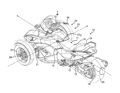
[0054] Figs. 4, 5 and 6, illustrate a three wheel vehicle 10 in
accordance with
a specific embodiment of the invention. The particular aesthetic design
details of the
MONTREAL 1857743.2
1106945
CA 02707303 2015-06-09
- 16 -
three wheel vehicle 10 are not critical to this invention, and these figures
merely
illustrate one possible configuration.
Vehicle Components and Systems
[0055] Vehicle 10 includes a frame 12 that supports and houses a
internal
combustion engine 14, but which could be any type of suitable power source
such as
an electric motor or hybrid engine if so desired. The engine includes a
conventional
Engine Management System (EMS) 107 (Fig. 8) that controls and regulates all
engine
functions such as RPM, torque, Otition, throttle, fuel injection, and
emissions using a
variety of conventional sensors and controllers (e.g. those described in US
Pat App
Ser No 11/627,780 and US Pat No 6,626,140). The EMS is electronically
connected
with the vehicle' s Electronic Control Unit (ECU) 110 (in Fig. 7), described
below.
[0056] A straddle seat 16 is mounted on the frame 12 and has a driver
seat 17
and a passenger seat 19 disposed behind the driver seat 17.
[0057] A single rear wheel 18 with a tire 20 suitable for road use is
suspended
via a rear suspension 15 at the rear of the frame 12 and is operatively
connected to the
engine 14 through a transmission including a gearbox and belt drive, although
any
suitable power transmission mechanism (e.g. continuously-variable
transmission,
chain drive, driveshaft assembly, etc.) could be used. A pair of front wheels
22 and 24
are suspended from the front of the frame 12 through suitable front suspension
21
including upper and lower A-arms. Dampening mechanisms including shock
absorber
and coil spring assemblies are associated with the front suspension 21 to
increase ride
comfort and vehicle stability. Front wheels 22 and 24 have tires 26 and 28
suitable for
road use mounted thereon. A vehicle speed sensor in the form of Hall-effect
wheel
speed sensors 86, 88, and 90, located at each wheel, generates signals
representative
of each individual wheel rotation rate. Sensors 86, 88, and 90 are
electronically
interconnected with the ECU 110.
[0058] Suitable tires 20, 26, 28 are those sold by Kenda USA of
Reynoldsburg, Ohio under model no. 79100. Front tires 26, 28 are size 165/65
R14
and the rear tire 20 is size 225/50 R15. The tires are made of Styrene-
Butadiene
7211672.1
34250/104
CA 02707303 2015-06-09
- 17 -
(SBR) copolymer and an approximate maximum coefficient of friction (l.tma.) of
1.0
laterally and 1.1 longitudinally.
[00591 A steering
system 30 is coupled to the front wheels 22 and 24 and is
supported by the frame 12 for transmitting steering commands to the front
wheels 22
and 24. The steering system 30 includes a steering column 32 and a handlebar
34,
although other suitable steering control mechanisms such as a steering wheel
could
also be used. A steering sensor 98 (in the form of a Hall effect sensor,
potentiometer,
or anisotropic magnetoresistence sensor (AMR)), is mounted to the steering
system 30
and generates signals representative of steering angle, a steering angle
variation rate,
and steering torque applied to tlie vehicle. The steering sensor 98 is
electronically
connected to the ECU 110. The steering system also includes a power steering
apparatus 29 of the type commonly used in recreational vehicles such as all-
terrain
vehicles (best shown in Fig. 7) including an electric motor and a reduction
gear (see
US Pat. No. 7,216,733 as an example). The power steering apparatus 29 is
electronically connected to the ECU 110 to provide status information thereto
and
receive control information therefrom.
[0060] As
illustrated in Fig 8, the frame 12 is a supporting structure to which
are connected the rear suspension 15 and the front suspension system 21. The
vehicle
10 is equipped with a yaw sensor 100 having integrated lateral acceleration
sensor and
longitudinal acceleration sensor, which is mounted onto the upper longitudinal
member 45 of the frame 12. The yaw sensor 100 is positioned in proximity to
the
vertical axis Z of the vehicle and center of gravity CG of the vehicle to
improve the
accuracy of the readings of the sensor and thus the information provided
thereby. The
yaw sensor 100 measures the rotational speed of the vehicle about the vertical
axis Z
and is a gyrometer that uses secondary Coriolis forces developed within non-
stationary systems. The integrated lateral and longitudinal acceleration
sensors
measure the acceleration of the vehicle along the transverse axis x and the
longitudinal axis y. They are Hall-type sensors. Other sensors such as a roll
rate
sensor (or, alternatively, a roll angle sensor), and a pitch rate sensor may
be added to
provide more vehicle status information. All of the sensors are interconnected
with
the ECU 110.
7211672J
34250/104
CA 02707303 2010-05-28
WO 2009/073636 18
PCT/US2008/085206
[0061] Fig. 9 schematically illustrates the braking system of the
three wheel
vehicle 10. The braking system comprises individual brakes 80, 82, and 84, at
each
wheel 18, 22, and 24 respectively, a master cylinder 92 hydraulically
connected to
each brake 80, 82, and 84, a hand brake lever 93 and a foot brake lever 95
either
hydraulically or mechanically connected to the master cylinder 92. The braking
system also includes an hydraulic modulator 96 with integrated primer pump
hydraulically positioned between the individual brakes 80, 82, and 84 and the
master
cylinder 92. The hydraulic modulator 96 is a basic component of an antilock
braking
system (ABS) which comprises at least two inlets channels 61, 62 and three
outlet
channels 63, 64, 65 (one for each individual brake). The master cylinder 92
typically
comprises two outlet hydraulic lines 66, 67, one for the front brake circuit
(66) and
one for the rear brake circuit (67), which are hydraulically connected to the
two inlet
channels 61, 62 of the hydraulic modulator 96. The inlet channel 62 receiving
the
front brake hydraulic line 66 splits into two outlet channels 64, 65, each
hydraulically
connected to one of the front brakes 82 and 84. The inlet channel 61 receiving
the rear
brake hydraulic line 67 is connected to a single outlet channel 63 which is
hydraulically connected to the rear brake 80. The hydraulic modulator 96 is
adapted to
regulate the pressure in the individual brakes 80, 82, and 84 independently of
braking
pressure applied by the driver. The braking system is therefore an integrated
Anti-lock
Braking System (ABS) that prevents wheel lock and improve braking efficiency.
The
braking system is electronically interconnected with the ECU.
[0062] The Electronic Control Unit (ECU) 110, comprising both a
computer
processor and memory, is responsible for vehicle electrical, electronic and
closed loop
control functions, including power supply to system sensors, recording
operating
conditions, converting, manipulating, and transmitting data, and network
linkage to
other controllers such as the EMS. The ECU 110 receives inputs from the
various
sensors and other vehicle operating systems (e.g. braking, power steering),
processes
the input data, and outputs signals to actuate certain operating parameters of
the
vehicle.
Electronic Stability System
MONTREAL 1857743.2
1106945
CA 02707303 2010-05-28
WO 2009/073636 19
PCT/US2008/085206
[0063] The
three wheel vehicle 10 is equipped with a specifically designed
Electronic Stability System (ESS). In general, an ESS includes a computer
processor
and processor readable memory containing both programming information
(software)
and data respecting the ESS's functions. In the case of vehicle 10 the ESS is
incorporated into the ECU 110 as part of the ECU's functions. (The ESS is not
separately physically distinguishable from the ECU in this embodiment, but in
other
embodiments it would be possible that it were.) The ECU determines the actual
vehicle dynamic status based on theses inputs, evaluates whether the vehicle
dynamic
status falls within or outside the limits of the specific stability envelope
of the three
wheel vehicle stored in memory and below or above specific maximum rate of
changes of the vehicle dynamic status stored in memory. Thereafter, if
required, the
ECU outputs specific signals to various vehicle systems of the three wheel
vehicle 10
to restore stability or in specific circumstances, to prevent (if possible)
the vehicle
from reaching the limits of the stability envelope of the three wheel vehicle.
[0064] FIG. 10 shows a basic block diagram of the ECU (ESS) 110 in
accordance with one embodiment of the invention. In operation, the ECU 110
receives inputs relating to at least some of the following factors: the yaw
rate from the
yaw sensor 100, wheel speed from the each wheel speed sensors 86, 88, and 90,
lateral acceleration also from the integrated lateral acceleration sensor 100,
longitudinal acceleration also from the integrated longitudinal acceleration
sensor 100
and steering angle from the steering angle sensor 98. This information is
processed
by the ECU 110 to evaluate the dynamic status of the three wheel vehicle and
compare it with data stored in memory defining the stability envelope of the
three
wheel vehicle 10 and specifically the wheel lift limits of the stability
envelope to
determine whether an intervention to stabilize the vehicle is required.
Various
intervention schemes corresponding to specific dynamic status are stored in
memory
and are described hereinbelow. If the dynamic status evaluated by the ECU
requires
an intervention, the ECU generates output signals (according to an
intervention
scheme) to cause the braking system or the Engine Management System or the
power
steering system, or some combination thereof, to take action to attempt to
correct the
situation.
MONTREAL 1857743.2
1106945
CA 02707303 2010-05-28
WO 2009/073636 20
PCT/US2008/085206
[0065] Fig.
11 shows a flow diagram of a control strategy 500 employed by an
ESS of the present invention. Initially, and continuously, as a first step 502
the ECU
receives input from the various sensors related to vehicle information
including the
longitudinal acceleration and the lateral acceleration and engine information
from the
EMS (the ECU may or may not additionally process this information ¨ as the
case
may require). The ECU then 504 compares data with values stored in memory or
values calculated from information stored in memory depending on the
circumstances. The ECU then 506 determines whether a precursory condition
indicative of a wheel lift exists. If such a condition does exist, the ECU
then 508
determines whether the vehicle is over its tire grip threshold (i.e. has the
tire grip
threshold of any of the tires been exceeded). If the vehicle is not over its
tire grip
threshold, the ECU will cause 510 the reduction of the longitudinal
acceleration of the
vehicle by an amount less than that which would cause the vehicle to exceed
its tire
grip threshold (i.e. the grip threshold of at least one of the tires to be
exceeded). If,
however, the vehicle is over its tire grip threshold, the ECU will determine
whether a
reduction in lateral acceleration is necessary 512. If no reduction in lateral
acceleration is necessary, the ECU will cause 514 the longitudinal
acceleration of the
vehicle to be reduced, which will cause the vehicle to exceed its tire grip
threshold if
it has not already been exceeded (the vehicle or a part thereof will be
skidding or
begin to skid, depending on the circumstances). If a reduction in lateral
acceleration is
necessary, the ECU will cause the longitudinal acceleration and lateral
acceleration to
be reduced 516. Returning back to step 506, if a precursory condition of a
wheel lift
does not exist, the ECU will then 518 determine whether a precursory condition
of
exceeding the tire grip exists. If this is true, then 520 the ECU will cause a
reduction
in the acceleration of the vehicle (this, depending on the circumstance could
be the
lateral acceleration, the longitudinal acceleration, or a combination of both)
or
maintain the vehicle acceleration at its current value (as the case may be) to
prevent
the tire grip threshold from being exceeded. If not, then no action will be
caused to be
taken by the ECU. In all cases, the ECU returns back to 500 and receives new
input
from the sensors and begins the process again.
[0066]
Referring now to Fig. 3, as an example, if at a particular point in time
the acceleration of the vehicle is at point A when plotted on the graph, point
A being
within the shaded area 220 (i.e. is at a point wherein a precursory condition
indicative
MONTREAL 1857743.2
1106945
CA 02707303 2010-05-28
WO 2009/073636 21
PCT/US2008/085206
of wheel lift exists) and the tire grip threshold not having been exceeded,
corrective
action will be taken to reduce the longitudinal acceleration to point B. It
will be noted
that point B is outside of and lower on the graph than the shaded area 220 and
therefore (all other things being equal) is generally a more acceptable
acceleration in
terms of likelihood of wheel lift. It will also be noted that the lateral
acceleration of
the vehicle at point B is the same as that as at point A. With acceleration
being as it is
at point B, the vehicle can accommodate a greater increase in lateral
acceleration than
at point A before reaching its wheel lift threshold 216 (compare distance 224
with
distance 222). Further when the acceleration is at point B, the vehicle has
not crossed
the tire grip threshold and therefore the tires still have traction.
[0067] The ESS is continually operative and thus assuming that after
a short
period of time the operating conditions of the vehicle have changed such that
acceleration of the vehicle when plotted on the graph would now be at point C.
Under
such circumstances the ECU could again reduce the longitudinal acceleration to
point
D in a similar manner as described above.
[0068] Continuing with the above example, if after another short
period of
time the operating conditions of the vehicle have again changed such that the
acceleration of the vehicle is at point E when plotted on the graph. (The
previous
reductions from A to B and from C to D collectively being the "first amount"
of
reduction within the context of the present invention.) At this point, as a
precursory
condition indicative of wheel lift exists, the ESS may act in two different
manners
(depending on programming). In a first instance the ESS may reduce both the
lateral
acceleration and the longitudinal acceleration of the vehicle to point F.
(Reduction by
unequally braking the wheels so as to generate a yaw moment would be the
preferred
method of so doing.) In this manner, the ESS has enhanced the stability of the
vehicle
such that the vehicle remains within the tire grip threshold. Alternatively,
the ESS
may reduce solely the longitudinal acceleration of the vehicle to a point G.
While
wheel lift has been prevented, the acceleration at point G is, however, beyond
the tire
grip threshold, so the vehicle has begun to skid. This is situation which the
driver of
the vehicle may correct by reducing the lateral acceleration of the vehicle.
[0069] An ESS of the present invention will also act like a
conventional ESS
(assuming it is so programmed) in situations where there is no precursory
condition
MONTREAL 1857743.2
1106945
CA 02707303 2010-05-28
WO 2009/073636 22
PCT/US2008/085206
indicative of a wheel lift yet the tire grip threshold is likely to be
exceeded (i.e. a
precursory condition indicative of exceeding tire grip threshold exists). Such
a
situation would be at point H in Fig. 3. Point H is not within shaded area 220
and
thus a precursory condition indicative of a wheel lift does not exist.
Nonetheless, it
can be seen that if the longitudinal acceleration of the vehicle increases the
tire grip
threshold will be crossed. In such a situation, the ESS will either reduce the
longitudinal acceleration or maintain the longitudinal acceleration (i.e.
prevent its
further increase), depending on its programming, in order to prevent the
vehicle from
crossing the tire grip threshold. This "precursory condition indicative of
exceeding
tire grip threshold" has been graphically shown in Fig. 3 as dotted areas 226
and 228.
[0070] Modifications and improvements to the above-described
embodiments
of the present invention may become apparent to those skilled in the art. The
foregoing description is intended to be exemplary rather than limiting. The
scope of
the present invention is therefore intended to be limited solely by the scope
of the
appended claims..
MONTREAL 1857743.2
1106945