Note: Descriptions are shown in the official language in which they were submitted.
CA 02707324 2010-06-11
File no. P1259CA00
BOILER WITH IMPROVED HOT GAS PASSAGES
CROSS-REFERENCE TO RELATED APPLICATIONS
[0001] This application claims priority under 35USC 119(e) of US provisional
patent application 61/222,050, filed on June 30, 2009. For the US only, the
specification of the foregoing provisional patent application is hereby
incorporated
by reference.
TECHNICAL FIELD
[0002] This description relates to the field of boilers for heating a fluid.
More
particularly, this description relates to boilers with tubes.
BACKGROUND
[0003] Boilers for heating a cold fluid (e.g. water, steam, thermal oil or any
other
heating medium) with a hot fluid (e.g. hot gases) with tubes are well known.
Many
improvements were provided in the past. In order to enhance the efficiency,
number of isolated passages was increased by adding separators, plates or
baffles
among the tubes. These additional parts among the tubes are exposed to the hot
fluid and thus require maintenance and decrease the availability of the
boiler.
These additional parts could also generate noise nuisance.
[0004] In order to enhance the efficiency, economizers are provided to be
installed
outside the boiler for saving energy released in the hot fluid escaping from
the
boiler. This type of economizer is separated to the boiler and need an
external
assistance (e.g. pump) for the circulation of the cold fluid trough the
economizer.
The external assistance consumes energy and thus decreases the global
efficiency
of the boiler.
[0005] Also, the transfer of the hot fluid from one passage to another is done
with a
particular pattern of tubes at the ends of the passages. That increases the
number
of types of tube to keep in inventory at the different level of the supply
chain.
- 1 -
CA 02707324 2010-06-11
File no. P1259CA00
SUMMARY
[0006] According to an aspect, there is provided a boiler for heating a cold
fluid with
a hot fluid. The boiler comprises: a lower drum; an upper drum; a plurality of
right
tubes for conveying the cold fluid, each of the right tubes fluidly connecting
the
lower drum and the upper drum, the right tubes forming a right wall, each of
the
right tubes comprising at least one left inwardly extending portion extending
toward
a left wall; and a plurality of left tubes for conveying the cold fluid, each
of the left
tubes fluidly connecting the lower drum and the upper drum, the left tubes
forming
the left wall facing the right wall, each of the left tubes comprising at
least one right
inwardly extending portion, each extending toward the right wall; wherein the
at
least one right inwardly extending portion is contiguous to and staggered with
the
at least one left inwardly extending portion, forming at least two passages
between
the right wall and the left wall, each one of the at least two passages having
first
and second ends and being substantially isolated from each other between each
of
its respective first and second ends; in use, the hot fluid circulates in the
at least
two passages and heats the right tubes and the left tubes, thereby heating the
cold
fluid.
[0007] According to another aspect, there is provided a boiler for heating a
cold
fluid with a hot fluid. The boiler comprises: a lower drum; an upper drum; a
plurality
of tubes for conveying the cold fluid, each of the tubes fluidly connecting
the lower
drum and the upper drum, the tubes forming at least two passages each having
first and second ends and being substantially isolated from each other between
each of its respective first and second ends; and an end wall disposed at one
end
of the at least two passages, fluidly connecting the at least two passages;
the end
wall comprising a cavity allowing the hot fluid passing from one to another of
the at
least two passages by the cavity, wherein, in use, the hot fluid circulates in
the at
least two passages and heats the tubes, thereby heating the cold fluid.
[0008] According to another aspect, there is provided a boiler for heating a
cold
fluid with a hot fluid. The boiler comprises: a lower drum; an upper drum; a
plurality
- 2 -
CA 02707324 2010-06-11
=
File no. P1259CA00
of tubes for conveying the cold fluid, each of the tubes fluidly connecting
the lower
drum and the upper drum, the tubes forming a passage having first and second
ends; and an additional exchanger; the additional exchanger comprising a cold
inlet, a cold outlet, a hot inlet and a hot outlet; the cold inlet being
fluidly connected
to the lower drum, the cold outlet being fluidly connected to the upper drum,
the hot
inlet being fluidly connected to one end of the passage for receiving the
previously
cooled hot fluid; wherein in use, the hot fluid circulates in the passage and
heats
the tubes, thereby heating the cold fluid, then the hot fluid crosses the
additional
exchanger and exhausts by the hot outlet, the cold fluid, being subjected to a
difference in temperature between the cold inlet and the cold outlet, flows
upwardly
from the lower drum to the upper drum crossing the additional exchanger
thereby
heating the cold fluid.
BRIEF DESCRIPTION OF THE DRAWINGS
[0009] Further features and advantages of the present invention will become
apparent from the following detailed description, taken in combination with
the
appended drawings, in which:
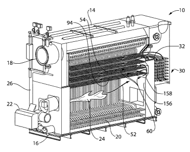
[0010] Fig. 1 is a partial cut-out perspective of a boiler 10 in accordance
with an
embodiment;
[0011] Fig. 2 is another partial cut-out perspective of the boiler 10;
[0012] Fig. 3 is a front perspective of a tube arrangement 34 of the boiler
10;
[0013] Fig. 4 is a rear perspective of the tube arrangement 34;
[0014] Fig. 5 is a rear perspective of the boiler 10;
[0015] Fig. 6 is a scheme of a pattern 86 of tubes of the boiler 10;
[0016] Fig. 7 is a scheme of a pattern 96 in accordance with another
embodiment;
[0017] Fig. 8 is a scheme of a pattern 112 in accordance with another
embodiment;
- 3 -
CA 02707324 2010-06-11
File no. P1259CA00
[0018] Fig. 9 is a scheme of a pattern 126 in accordance with another
embodiment;
[0019] Fig. 10 is a scheme of a pattern 138 in accordance with another
embodiment;
[0020] Fig. 11 is a schematic view of a circulation of a hot fluid in a boiler
in
accordance with another embodiment;
[0021] Fig. 12 is a schematic view of a circulation of a hot fluid in a boiler
in
accordance with another embodiment; and
[0022] Fig. 13 is a schematic view of a circulation of a hot fluid in a boiler
in
accordance with another embodiment.
[0023] It will be noted that throughout the appended drawings, like features
are
identified by like reference numerals.
DETAILED DESCRIPTION
[0024] Referring now to the drawings and more particularly to Fig. 1 and Fig.
2, 3
and 4, there is respectively shown from the front and from the rear a boiler
10 in
accordance with an embodiment. The boiler 10 is usually installed in a closed
circuit, not shown, for heating a fluid and delivering it through a boiler
outlet 12 as
an external flow. The fluid circulates in a network comprising radiators,
exchangers
or turbines which decrease the temperature of the fluid, then the fluid flows
back
into the boiler 10 through a boiler inlet 76 to be heated again. According to
an
embodiment, the fluid is warm water or steam; it could also be a high specific
heat
capacity fluid or other convenient fluid or heating medium.
[0025] The boiler 10 comprises a housing 14 enclosing a lower drum 16, an
upper
drum 18 and a plurality of tubes 20 fluidly connecting the lower drum 16 and
the
upper drum 18. The boiler inlet is connected to the lower drum 16 and/or to
the
economizer inlet 62 for receiving the fluid coming from the network which is
called
the cold fluid. A burner 22 produces a hot fluid 24, usually hot gases from
combustion, which circulate among the tubes 20 for heating the cold fluid. The
cold
- 4 -
CA 02707324 2010-06-11
File no. P1259CA00
fluid being heated in the tubes 20 naturally migrates from the lower drum 16
to the
upper drum 18. The lower drum 16 and the upper drum 18 are fluidly connected
by
a front down comer 26 and a rear down comer 28 for creating a high rate cold
fluid
internal flow downwardly from the upper drum 18 to the lower drum 16.
[0026] At the rear, the boiler 10 comprises an economizer 30, also referred to
as an
additional exchanger receiving from the top or the bottom hot fluid 32 usually
hot
gases, previously cooled by the tubes 20, . The economizer 30 heats the cold
fluid
which, due to a difference in temperature between a lower cold fluid inlet and
an
upper cold fluid outlet, naturally flows from the lower drum 16 and flowing up
to the
upper drum 18.
[0027] Referring to Fig. 3, there is shown a tube arrangement 34 of the boiler
10
according to an embodiment. The tube arrangement 34 comprises a plurality of
left
tubes 36 for conveying the cold fluid. Each of the left tubes 36 fluidly
connects the
lower drum 16 and the upper drum 18. The tubes may be connected to the drums
by welding directly or by means of ferrules. The left tubes 36 form a left
wall 38.
According to an embodiment, each of the left tubes 36 comprises two right
inwardly
extending portions 40, 42 each extending toward a right wall 44. The tube
arrangement 34 further comprises a plurality of right tubes 46 for conveying
the
cold fluid. Each of the right tubes 46 fluidly connects the lower drum 16 and
the
upper drum 18. The right tubes 46 form the right wall 44 facing the left wall
38.
According to an embodiment, each of the right tubes 46 comprises two left
inwardly
extending portions 48, 50, each extending toward the left wall 38.
[0028] The right inwardly extending portion 40 is contiguous to and staggered
with
the left inwardly extending portion 48 and the left inwardly extending portion
50,
forming three passages 52, 54, 56 between the left wall 38 and the right wall
44.
Of course all references to the left and the right are for convenience of
description
only. They can be reversed depending of the observer's point of view. This
description is therefore meant to cover any mirror image of the device shown
in the
Figures.
- 5 -
CA 02707324 2010-06-11
File no. P1259CA00
[0029] Each one of the three passages 52, 54, 56 has first end 58 and second
end
60 and are substantially isolated from each other between each of its
respective
first and second ends 58, 60. In use, the hot fluid circulates in the three
passages
52, 54, 56 and heats the left tubes 36 and the right tubes 46, thereby heating
the
cold fluid. Acco rding to another embodiment, there are only one left inwardly
extending portion and one right inwardly extending portion which are
contiguous
and staggered and which would create at least two passages.
[0030] The passages 52, 54, 56 are substantially isolated from each other. The
left
tubes 36 are substantially contiguous between themselves along their length.
The
right tubes 46 are similarly disposed. Moreover, the right inwardly extending
portion
40 is proximate to or in contact with the left inwardly extending portion 48
and the
left inwardly extending portion 50. In another embodiment (not shown),
insulation
is disposed between the tubes.
[0031] Turning now to Fig. 4, there is shown the tube arrangement 34 including
the
piping of the economizer 30. The economizer 30 is located between the lower
drum 16 and the upper drum 18 and comprises a cold inlet 62, a cold outlet 64,
a
hot inlet 66 and a hot outlet 68. The cold inlet 62 is fluidly connected to
the lower
drum 16 by a lower piping 70. The cold outlet 64 is fluidly connected to the
upper
drum 18 by an upper piping 72. The hot inlet 66 is fluidly connected to second
end
60 of upper passages 74 for receiving the previously cooled hot fluid 32. The
hot
inlet 66 is above the hot outlet 68, so that the previously cooled hot fluid
32 has a
downward movement while the cold fluid has an upward movement. According to
another embodiment, the hot inlet 66, the hot outlet 68, the cold inlet 62 and
the
cold outlet 64 can be reversed.
[0032] In use, the previously cooled hot fluid 32 circulates through the
economizer
30 and exhausts by the hot outlet 68. The cold fluid, due to a difference in
temperature between a cold inlet 62 and a cold fluid outlet 64, naturally
flows
upward from the lower drum 16 to the upper drum 18 crossing the economizer /
additional exchanger 30 thereby heating the cold fluid. Such a disposition
does not
- 6 -
CA 02707324 2010-06-11
File no. P1259CA00
need any external assistance like a pump to be operative. An additional inlet
76 is
fluidly connected to the cold inlet 62 for receiving additional cold fluid in
the boiler
and inserting the additional cold fluid directly in the economizer 30 for pre-
heating it before circulating in the tube arrangement 34. The additional inlet
76, can
also receive the cold fluid flowing back from the network instead of the
boiler inlet
13.
[0033] Referring now to Fig. 5, there is shown the rear of the boiler 10. A
duct 78 is
disposed for receiving the previously cooled hot fluid 32, for conveying it to
the hot
inlet, not shown, for receiving the previously cooled hot fluid 32 from the
hot outlet,
not shown, and for exhausting it by a hot fluid output 80. A receptacle 82 is
disposed at the bottom for receiving condensates 84.
[0034] Referring now to Fig. 6, there shown a pattern 86 of one of the left
tubes 36
and one of the right tubes 46 fluidly connecting the lower drum 16 and the
upper
drum 18. The right inwardly extending portion 40 is contiguous to the left
inwardly
extending portion 48 and to the left inwardly extending portion 50, such that
three
passages 52, 54, 56 are formed between the left wall 38 and the right wall 44.
The
left inwardly extending portion 50 is contiguous to the right inwardly
extending
portion 40 and to the right inwardly extending portion 42, such that three
passages
54, 56, 88 are formed between the left wall 38 and the right wall 44. The
right
inwardly extending portion 42 is contiguous to the upper drum 18, such that
two
passages 88, 90 are formed between the left wall 38 and the right wall 44.
[0035] Side plates 92 are disposed outside and against the left wall 38 and
the right
wall 44 forming four additional passages 94 with the right inwardly extending
portions 40, 42 and the left inwardly extending portions 48, 50. Such a
pattern
results in nine passages 52, 54, 56, 88, 90, 94 with two right inwardly
extending
portions 40, 42 and two left inwardly extending portions 48, 50.
[0036] Referring now to Fig. 7, there is shown a pattern 96 of a right tube 98
and a
left tube 100 according to another embodiment. A right inwardly extending
portion
- 7 -
CA 02707324 2010-06-11
File no. P1259CA00
102 is contiguous to a left inwardly extending portion 104 and to another left
inwardly extending portion 106, so that three passages 108 are formed. The
right
inwardly extending portion 102 is longer than the left inwardly extending
portions
104, 106. Sections of the passages 108 depend on a length 110 of each inwardly
extending portion.
[0037] Referring now to Fig. 8, there is shown a pattern 112 of a right tube
114 and
a left tube 116 according to another embodiment. A base portion 118 of the
right
tube 114, comprised between two left inwardly extending portions 120, is
distant to
a virtual base plan 122 comprising other base portions 124 of the right tube
114.
[0038] Referring now to Fig. 9, there is shown a pattern 126 of a right tube
128 and
a left tube 130 according to another embodiment. A right inwardly extending
portion 132 comprises a flat portion 134 which is contiguous to two left
inwardly
extending portions 136.
[0039] Referring now to Fig. 10, there is shown a pattern 138 of a right tube
140
and a left tube 142 according to another embodiment. The right tube 140 and
the
left tube 142 fluidly connect a lower drum 144 and an upper drum 146. The
lower
drum 144 comprises two lower manifolds 148 fluidly connected between
themselves. Similarly, the upper drum 146 comprises two upper manifolds 150
fluidly connected between themselves. The right tube 140 fluidly connects one
of
the lower manifolds 148 to one of the upper manifold 150 and the left tube 142
fluidly connects the other lower manifold 148 to the other upper manifold 150.
[0040] Returning now to Fig. 3, the tube arrangement 34 further comprises a
dividing plate 152 disposed along the passage 94 for dividing a circulation of
the
hot fluid in a portion of the at least one passage in two separate fluxes. The
tube
arrangement 34 further comprises a limiting plate 154 disposed across the
passage 94, limiting a section of a portion of passage 94.
[0041] Returning now to Fig. 1, the boiler 10 further comprises an end wall
156
disposed at one end 60 of the passages 52, 94, 54, fluidly connecting the
- 8 -
CA 02707324 2010-06-11
File no. P1259CA00
passages 52, 94, 54. The end wall 156 comprises a cavity 158 allowing the hot
fluid 24 to pass from the passage 52 to passages 94, 54 by the cavity 158.
Other
arrangements for cavity 158 are possible where the hot fluid 24 passes from
passage 52 to passage 94, but not to passage 54. Cavity 158 can also be
arranged to provide an end passage between two single longitudinal passages or
any other combination (e.g., two passages to one, two passages to two, etc.).
According to dispositions of cavities in the end walls, several circulations
of hot
fluid are envisioned as un-exclusively depicted on Fig. 11, Fig. 12 and Fig.
13,
concurrently referred to.
[0042] Fig. 11 shows a circulation 160 according to another embodiment. A hot
fluid 161 is generated in a passage 162 and divided into two passages 164 in
the
back. In the front, the hot fluid 161 is transferred from the two passages 164
into
two passages 166. In the back, the hot fluid 161 is transferred from the two
passages 166 into two passages 168. In the front, the hot fluid 161 is
transferred
from the two passages 168 into two passages 170. Each portion of the hot fluid
crosses through five passages in the boiler.
[0043] Fig. 12 shows a circulation 172 according to another embodiment. A hot
fluid 175 is generated in a passage 174 and divided into two passages 176 in
the
back. In the front, the hot fluid 175 is transferred from the two passages 176
into
two passages 178. In the back, the hot fluid 175 is transferred from the two
passages 178 into a passage 180. In the front, the hot fluid 175 is
transferred from
the passage 180 into a passage 184. In the back, the hot fluid 175 is
transferred
from the passage 184 into a passage 182. In the front, the hot fluid 175 is
transferred from the passage 182 into a passage 186. Each portion of the hot
fluid
crosses through seven passages in the boiler.
[0044] Fig. 13 shows a circulation 188 according to another embodiment. A hot
fluid 191 is generated in a passage 190 and transferred into a passage 192 in
the
back. In the front, the hot fluid 191 is transferred from the passage 192 into
a
passage 194. In the back, the hot fluid 191 is transferred from the passage
194 into
- 9 - '
CA 02707324 2010-06-11
File no. P1259CA00
a passage 196. In the front, the hot fluid 191 is transferred from the passage
196
into a passage 198. In the back, the hot fluid 191 is transferred from the
passage
198 into a passage 200. In the front, the hot fluid 191 is transferred from
the
passage 200 into a passage 204. In the back, the hot fluid 191 is transferred
from
the passage 204 into a passage 202. In the front, the hot fluid 191 is
transferred
from the passage 202 into a passage 206. Each portion of the hot fluid 191
travels
through nine passages in the boiler.
[0045] While embodiments have been described above and illustrated in the
accompanying drawings, it will be evident to those skilled in the art that
modifications may be made therein without departing from the essence of this
description. Such modifications are considered as possible variants comprised
in
the scope of the description.
-10-.