Note: Descriptions are shown in the official language in which they were submitted.
CA 02707347 2009-12-14
WO 2008/157056 PCT/US2008/065861
TELEVISION CONTENT CONTROL SYSTEM AND METHOD WITH CROSS-
PLATFORM CAPABILITY
CROSS-REFERENCE TO RELATED APPLICATION
[0001] This application claims priority to U.S. provisional application No.
60/934,723 filed
June 15, 2007, and incorporated herein by reference in its entirety.
FIELD OF THE INVENTION
[0002] This disclosure relates to video and television (TV) and more
specifically to content
management of TV and video signals.
BACKGROUND OF THE INVENTION
[0003] Content management or content control is well known in the information
field, and
generally refers to controlling use of audio and video material. Often such
content control
involves modifying a digital video signal to include tags or trigger bits or
flags which define
how the material can be used by various downstream devices. One aspect of
content
management is copy protection, typically carried out in the analog domain.
Generally copy
protection refers to methods and apparatus for processing a video signal to
inhibit making of
acceptable video recordings and is also referred to here as anticopy process
(ACP).
[0004] The broader field of content control includes use of so called
compliant devices that
are designed to include circuitry or software that detects certain
predetermined signals (or the
absence of same) in a received video signal. The presence (or absence) of the
particular
signal is interpreted as a command to the receiving device to enable or
inhibit recording, for
instance, or storage or further transmission. In some cases, this control
involves generational
copy management where a first generation copy may be made, but subsequent
generation
copies are prevented. Such copy management is applicable to digital video
signals of the
1
CA 02707347 2009-12-14
WO 2008/157056 PCT/US2008/065861
types used on video media, such as DVDs and also other types of television
signals, including
high definition television. These more sophisticated copy control systems
typically require
dedicated circuitry and/or software in the receiving device to detect and
interpret special data
provided in the video signal for purposes of content management.
[0005] US 2006/0093140 Al, inventor Ronald QUAN and entitled Content
Management
for High Definition Television and incorporated here by reference in its
entirety, is directed
to content management in the realm of high definition television video signals
using tri-level
sync pulses and is incorporated herein by reference in its entirety. High
definition (HD)
television is a well-defined video standard. However typically in the video
field television
signals are processed between devices which do not necessarily adhere to the
same television
standard and/or which may be receiving signals in different television
standards. (Television
is a type of video, adapted for transmission over the air, by cable, or by
satellite.) Television
standards refer to both the well-known so-called legacy television standards
which has been
around for a long time and generally operating in the analog domain, including
NTSC, PAL,
SECAM, VGA and others. Also included are the various newer digital television
standards,
including the 720p standard which provides a picture with 720 vertical lines
each with 1,280
pixels horizontally. The p refers to progressive scanning as used in computer
displays.
HDTV (high definition television) is replacing analog standard (NTSC in the
United States)
television. Somewhat different HDTV formats are being adopted by different
countries and
groups of countries typically using different frame rates, as is the case with
legacy television.
Digital TV (DTV) here refers to particular television formats and is not
necessarily the same
as so-called digital cable television. Digital TV (in this sense, actually
digital broadcast
television) actually defines (in the U.S.) eighteen different formats for
broadcast television in
digital format. Currently, HDTV represents at least six of those eighteen
formats.
2
CA 02707347 2009-12-14
WO 2008/157056 PCT/US2008/065861
SUMMARY
[0006] The present inventors have identified a need to provide a content
control system
usable for multiple TV standards and that is operative with the conventional
content
management information such as flags, control bits, data, copy protection
signal(s), and/or
modification signals. In particular, content control (including copy control
also referred to
here as copy protection) for high definition TV signals is needed in future TV
devices such as
TV transmitters, signal translators, recorders, players, displays, or the
like. Because there is
also a need to accommodate "legacy" TV standards such as 240p, NTSC, PAL,
SECAM,
VGA, etc., a new content control system is needed to combine the legacy
standards with
newer TV higher definition standards such as 720p, 1080i, 1080p, etc. for
content control.
[0007] Currently available TV/video circuits and sets accommodate various TV
resolutions
(standards), and also tailor each TV standard with specific or programmable
copy/content
signal(s). What is used in terms of copy/content control with a composite TV
signal such as
NTSC or PAL, may not be applicable directly to an RGB or component video
waveform. For
example, a color stripe subcarrier signal for copy control is applicable to
NTSC or PAL TV,
but not applicable to a component TV/video waveform that lacks a subcarrier
signal. One
embodiment operates with various TV standards for high definition TV. By
mapping from
one TV standard's copy/content control signal(s) to another, a cross platform
system is
achieved.
[0008] Copy/content control across various platforms with differing TV
resolutions may be
implemented by reception of a transmitted signal such as via fiber, satellite,
Internet, cable, or
phone lines (DSL or dial up) to receive data or programming information to
configure
copy/content control signals for different TV standards including HDTV. One
can also store
the configuration information via media and/or memory (e.g., solid state,
magnetic, and/or
3
CA 02707347 2009-12-14
WO 2008/157056 PCT/US2008/065861
optical), and use the stored configuration information to program the
copy/content control
signal across many TV standards. Thus, the configuration (of copy/content
control signals
and/or detection of such signals for multiple resolutions) is changeable or
can be updated.
[0009] A goal of mapping copy/content control signals across different TV
standards is to
add security to the control system. A secure control system does not allow for
a "loophole"
so that all standards have some type of recognizable control signal, such that
conversion to
another standard is limited or prohibited or, is forced to output the
converted video signal
with an added copy/content control signal.
[0010] One embodiment of the invention encodes or modifies video signals
conforming to
one or a plurality of HD (high definition) TV standards. TV signals conforming
to each
standard may include one or more modifications to a portion of the HD signal.
For example,
each HDTV standard may have its own type of modification or a modification
that is in
common with another HDTV standard.
[0011] Another embodiment is an apparatus or method for providing, generating,
synthesizing, or processing a tri-level sync (synchronization) video signal
into a video signal
with modified levels in a portion of the tri-level sync video signal (e.g.,
which may combined
with specific copy/content control bits) for at least one HDTV standard (e.g.,
TV is a
combined video and audio signal.)
[0012] Another embodiment is an apparatus that provides a high definition
copy/content
control signal along with a providing a standard definition copy protection
signal and/or
standard definition content control signal.
[0013] Another embodiment is a reader or detector, which senses, reads, or
detects a
standard definition video signal with content control or copy protection
signals along with the
4
CA 02707347 2009-12-14
WO 2008/157056 PCT/US2008/065861
capability to detect modifications on an HD video signal. For example, this
may be a
detector or reader device or software program that is capable of detecting
signal
modifications in SD and/or HD. The reader or detector may be imbedded in a
particular
device or circuit.
[0014] Yet another embodiment is a digital TV tuner, device, and/or receiver,
which
receives DTV (digital television) in the form of HDTV and/or SDTV, and/or
includes a
converter for producing a scaled analog and/or digital signal, which includes
generating copy
protection, data, and/or content control signal(s) for one or more analog and
digital TV
output. (Note that such video signal conversions, without the content/copy
control aspect, are
routine in the field.) One example includes generation of a modified HDTV
signal with the
capability of adding one or more copy control signals in the SDTV standard.
For example, a
modified HDTV (and/or SDTV) type signal may include modified sync pulses,
conventional
AGC (Automatic Gain Control) pulses, a data signal added to an overscan area,
raised or
lowered portion in an overscan area of a TV picture, and/or conventional
pseudo sync pulses.
For example, reading or sensing any of the modification(s) in the HDTV signal
may result in
a subsequent modification in a SD video signal. Such video conversion is
routine and is done
by up sampling or down sampling of TV lines and fields. Commercially available
products
such as certain DVD players do this.
[0015] The tuner, device, and/or receiver may for example, process signals
that include RF
modulated signals complying to the U.S.A.'s FCC or international broadcast
specifications
for "off air" broadcasting for analog and/or digital RF signals (e.g.,
vestigial AM, quadrature
AM, DTV, ATSC, multilevel VSB, QAM multi-bit, PSK, AM, WiFi, WiMax, and/or FM)
along with analog NTSC or equivalent composite video signals, computer
component video
CA 02707347 2009-12-14
WO 2008/157056 PCT/US2008/065861
signals, component vide signals, digital signals such as HDMI, SDI, DVI, USB,
and/or
Firewire.
[0016] In one embodiment, the detector outputs a signal indicative (or a
signal lacking the
presence) of a content control signal modification in SD and/or HD. This
output signal may
or may not be used later on. For example, upon detection of a modification, an
output or
input video signal may be modified, shut down, or recorded in a particular
manner (e.g., not
able to record, record for a particular time period, recorded with added
content control or
copy protection signal, recorded with a different resolution, or the like).
[0017] Another embodiment is an apparatus wherein one or more input analog
and/or
digital TV signal(s) are coupled into the apparatus and wherein one or more
video signal
output(s) are output from the device. This device may receive a modified input
video signal
(e.g., containing one or more content control signals and/or at least part of
a copy protection
signal of one standard to couple/provide a content control signal and/or at
least part of a copy
protection signal of another standard.) For example, an analog and/or video
signal for HD is
coupled to the input of such a device (e.g., transcoder, A/D and/or D/A, cross
platform
standards converter, etc.) with a modification may yield a modification to an
SD (or HD or
digital) signal for one or more outputs (or vice versa).
[0018] The content control modification may include any combination of: one or
more
positive going pulses, one or more negative going pulses, a data signal, one
or more incorrect
color signals, level shifting (e.g., positive and/or negative level shifting)
in a portion of the
video signal, one or more sync pulse modifications (e.g., position, pulse-
width, and/or
amplitude), added signal(s) to at least a portion of the vertical and/or
horizontal blanking
interval(s), modified color burst of at least one cycle of incorrect phase
and/or frequency,
modulated signal that is added/inserted in a portion of the video signal
(wherein the
6
CA 02707347 2009-12-14
WO 2008/157056 PCT/US2008/065861
modulated signal may include any combination of quadrature modulation, AM, FM,
frequency hopping, PCM, PWM, PPM, spread spectrum modulation, PSK, BPSK, FSK,
BFSK, and/or the like), which may be including one or more control bits, one
or more
configuration bits, and/or the like.
[0019] Another embodiment includes in the realm of copy protection various TV
horizontal
blanking interval signal back porch (or front porch) modifications to one or
more HD TV
standards. These HD modifications may include any number or series of positive
and/or
negative going pulses/signals in the TV signal back porch in addition to
and/or in place of the
back porch pulses. For example, one or more HD back porch pulses (or HD pseudo
sync
signal(s)) may be used for detection by a reader, and/or for encoding for
downstream content
control purposes.
BRIEF DESCRIPTION OF THE FIGURES
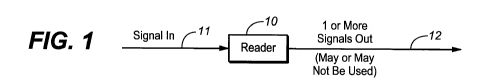
[0020] Figure 1 shows a reader apparatus.
[0021] Figure 2A shows an encoder or modifier.
[0022] Figure 2B shows a generator or signal provider.
[0023] Figure 2C shows a scaler or transcoder.
[0024] Figure 3 shows a modifier.
[0025] Figure 4 shows a circuit, device, apparatus, and/or software.
[0026] Figure 5 shows signals and/or modification to a signal.
[0027] Figure 6 shows waveform modifications to one or more HD signal(s).
[0028] Figures 7A-7G and 8A-8E and 9 show modifying a color signal.
7
CA 02707347 2009-12-14
WO 2008/157056 PCT/US2008/065861
[0029] Figure 10 shows a combination of circuit(s) and/or software program(s).
[0030] Figures 11A and 11B show a color stripe detector or phase detector.
[0031] Figures 12A and 12B show prior art network or distribution systems.
[0032] Figures 13A to 13D show embodiments with mapping and/or detection
methods.
[0033] Figures 14A and 14B show transforming from one TV standard to another
including
content control or copy protection signal(s).
[0034] Figures 15-19 show mapping relations or functions in matrix form for
various TV
formats and content control signal(s).
[0035] Figure 20 shows in a table an example of various signal modifications
for different
TV standards.
[0036] Figure 21 shows examples of content control signal mapping in matrix
form from a
same or different TV standard.
[0037] Figure 22 shows a reader or detector in a block diagram.
[0038] Figure 23 shows a scaler (converter) in a block diagram.
DETAILED DESCRIPTION
[0039] In accordance with the present invention, control or configuration
bit(s) in a TV
signal may be used to set or provide one or more modifications to a HD, SD
(standard
definition), or Low Definition (e.g., low definition may be less than 525
lines) video signal.
For example, the content control system defined in the following tables is
used in exemplary
embodiments.
8
CA 02707347 2009-12-14
WO 2008/157056 PCT/US2008/065861
TABLE 1
Mode Control Bit Listing
Routine On/Off and Mode Selection
NO On/off and mode control; 8 bits
NO[7] Reserved CPCO[3]
NO[6] Pay-to-tape allowed/prohibited (Allowed = 1, CPCO[2]
Default = 0)
NO[5] VBI pulses On/Off (VBIP) (ON = 1) CPCO[1]
NO[4] End of Field Back Porch Pulses on/off (ON = 1) CPCO[O]
(EOFP)
NO[3] Colorstripe process On/Off (CSP) (ON = 1) CPC1[3]
NO[2] AGC pulse normal (amplitude (Cycling = CPC1[2]
cycling)/static mode select (AGCY) Default = 1)
NO[1] H-sync amplitude reduction On/Off (ON = 1) CPC1[1]
(HAMP)
NO[O] sync amplitude reduction On/Off (ON = 1) CPC1[0]
(VAMP)
[0040] Table 1 shows a copy control specification using a set of 8 digital
data bits
designated NO[O] to NO[7] to be inserted into or provided with a video signal
as described
herein to define various control management states. The first column shows the
bit number
(zero to 7, where 7 is not used). The second column shows the control
management state in
terms of e.g. pay-to-tape (bit 6) or various well known analog domain copy
prevention
schemes, operating in the analog video domain, as defined by Macrovision
Corp., see US
Patent 6,381,747 incorporated herein by reference in its entirety. The third
column shows the
significance of each bit being "ON" (value 1) or OFF (value zero). The fourth
column refers
to CPC, copy protection control or commands CPC[O] to CPC[3].
TABLE la
Summary of 525/60/NTSC Measurements
Parameter Measurement
( S)
Burst Normal Start Point (Colorstripe Line) 5.3 0.15
Burst Advanced Start Point (Colorstripe Line) 4.96 0.15
(Note 1)
Envelope Rise Time 10%-90% 0.3 +0.1/-0.2
Burst Start to First Phase Switch Point 1.48 0.07
First to second phase switch points 0
Second Phase Switch Point to end of burst 1.48 0.15
9
CA 02707347 2009-12-14
WO 2008/157056 PCT/US2008/065861
(Note 1)
Envelope Fall Time 10%-90% 0.3 +0.1/-0.2
Note 1: Start and End points must be such that total burst duration for the
default configuration is 2.96+0.15/-0.07
[0041] Table la shows in the prior art for the NTSC TV standard (525
lines/field, 60
frames/second) timing information in terms of an NTSC video waveform for the
Macrovision
Corp. well known color stripe process which is bit 3 in Table 1. ("Burst" in
Table 1a refers
to the video color burst.)
CA 02707347 2009-12-14
WO 2008/157056 PCT/US2008/065861
TABLE 1b
LINE NUMBERS INCORPORATING
ADVANCED SPLIT BURST WAVEFORM (NTSC)
Advanced Split Burst Advanced split Burst
4-Line version 2-Line version
(21-Line Spacing) (17-Line Spacing)
First line in stripe First line in stripe
Stripe No. Field 1 Field 2 Field 1 Field 2
1 24 297 30 301
2 45 318 47 318
3 66 339 64 335
4 87 360 81 352
108 381 98 369
6 129 402 115 386
7 150 423 132 403
8 171 444 149 420
9 192 465 166 437
213 486 183 454
11 234 507 200 471
12 217 488
13 234 505
[0042] Table 1b similarly provides detail in the prior art of the color stripe
process of Table
1. This process is conventionally used in a 2 (video) line and 4 (video) line
format. "Split
burst" refers to the feature in the color stripe process where only a part of
the color burst is
altered. The color burst process, as defined in Table 1b, is only present on
the selected video
lines as shown.
11
CA 02707347 2009-12-14
WO 2008/157056 PCT/US2008/065861
TABLE 2a
Summary of 625/50/PAL Measurements
Parameter Measurement
( S)
Burst Normal Start Point (Colorstripe Line) 5.6 0.15
(Note 1)
Burst Advanced Start Point (Colorstripe Line) 4.96 0.15
Envelope Rise Time 10%-90% 0.3 +0.1/-0.2
Burst Start to First Phase Switch Point 1.185 0.07
First to second phase switch points 0
Second Phase Switch Point to end of burst 1.185 0.15
(Note 1)
Envelope Fall Time 10%-90% 0.3 +0.1/-0.2
Note 1: Start and End points must be such that total burst duration for the
default configuration is 2.25+0.15/-0.07
TABLE 2b
LINE NUMBERS INCORPORATING
COLORSTRIPE BURST WAVEFORM (PAL)
Colorstripe Burst
2 or 3-Line version
(34-Line Spacing)
First line in stripe
Stripe No. Even Field Odd Field
1 27 356
2 61 390
3 95 424
4 129 458
163 492
6 197 526
7 231 560
8 265 594
[0043] Tables 2a and 2b are in the prior art similar respectively to Tables 1a
and 1b, for
PAL standard television (common outside the U.S.A.) having 625 lines per field
and 50
frames per second.
Table 3
System Type Samples [Active rame Scanning uma uma C G otal
er Active [Lines per ate (Hz) ormat Sampling Sampling PP ines per
inc rame re uency eriod (T) ulse rame
12
CA 02707347 2009-12-14
WO 2008/157056 PCT/US2008/065861
(MHz) (nS) Width
1920x1080/60/1:1 1920 1080 60 Progressive 148.500 6.734 4T 44T 44T 148T 280T
1920T 2200T 4T 1125
1920x1080/59.94/1:1 1920 1080 59.95 Progressive 148.352 6.741 4T 44T 44T 148T
280T 1920T 2200T 4T 1125
1920x1080/50/1:1 1920 1080 50 Progressive 148.500 6.734 84T 44T 44T 148T 720T
1920T 2640T 4T 1125
1920x1080/60/2:1 1920 1080 30 2:1 Interlace 74.250 13.468 4T 44T 44T 148T 280T
1920T 2200T 4T 1125
1920x1080/59.94/2:1 1920 1080 29.97 2:1 Interlace 74.176 13.481 4T 44T 44T
148T 280T 1920T 2200T 4T 1125
1920x1080/50/2:1 1920 1080 25 2:1 Interlace 74.250 13.468 1484T 44T 144T 14ST
720T 1920T 2640T 144T 1125
1920x1080/30/1:1 1920 1080 30 Progressive 74.250 13.481 4T 14T 44T 148T 280T
1920T 2200T 4T 1125
1920x1080/29.97/1:1 1920 1080 29.97 Progressive 74.176 13.468 4T 14T 44T 148T
280T 1920T 2200T 4T 1125
1920x1080/25/1:1 1920 1080 25 Progressive 74.250 13.481 84T 14T 44T 148T 720T
1920T 2640T 4T 1125
1920x1080/24/1:1 1920 1080 24 Progressive 74.250 13.468 594T 14T 44T 148T 830T
1920T 2750T 4T 1125
1920x1080/23.98/1:1 1920 1080 23.98 Progressive 74.176 13.481 594T 14T 44T
148T 830T 1920T 2750T 4T 1125
1920x1080/30/1:1 SF 1920 1080 30 cog. SF 74.250 13.468 4T 14T 44T 148T 280T
1920T 2200T 4T 1125
1920x1080/29.97/1:1 SF 1920 1080 29.97 cog. SF 74.176 13.481 4T 14T 44T 148T
280T 1920T 2200T 4T 1125
1920x1080/25/1:1 SF 1920 1080 25 cog. SF 74.250 13.468 84T 44T 44T 148T 720T
1920T 2640T 4T 1125
1920x1080/24/1:1 SF 1920 1080 24 cog. SF 74.250 13.468 594T 44T 44T 148T 830T
1920T 2750T 4T 1125
1920x1080/23.98/1:1 SF 1920 1080 23.98 cog. SF 74.176 13.481 594T 44T 44T 148T
830T 1920T 2750T 4T 1125
1280x720/60/1:1 1280 720 60 Progressive 74.250 13.468 70T 0T OT 220T 370T
1280T 1650T OT 750
1280x720/59.94/1:1 1280 720 59.94 Progressive 74.176 13.481 70T 0T OT 220T
370T 1280T 1650T OT 750
1280x720/50/1:1 1280 720 50 [Progressive 74.250 13.468 OOT 0T 0T 220T 700T
1280T 1980T OT 750
1280x720/30/1:1 1280 720 30 Progressive 74.250 13.481 1720T 0T OT 220T 2020T
1280T 3300T 140T 750
1280x720/29.97/1:1 1280 720 29.97 Progressive 74.176 13.468 1720T 0T OT 220T
2020T 1280T 3300T OT 750
1280x720/25/1:1 1280 720 25 oaressive 74.250 13.481 2380T 0T OT 220T 2680T
12801 3960T OT 750
1280x720/24/1:1 1280 720 24 Progressive 74.250 13.468 2545T 0T OT 220T 2845T
1280T 125T OT 750
1280x720/23.98/1:1 1280 720 23.98 Progressive 74.176 13.481 2545T 140T OT 220T
2845T 1280T 125T OT 750
Note: BBP Pulse Width measured at 50% points of leading and trailing edges of
the pulse.
[0044] Table 3 shows in each line (row) a known HDTV format (standard), and in
each
column relevant parameters for that format. Columns A, B, C, D, E, F, G refer
to the
waveform parameters shown in Fig. 6, which shows a waveform for tri level sync
pulse in a
TV signal. A refers to a front porch duration, B refers to a negative going
sync pulse
duration, C refers to a positive going sync pulse duration, D refers to a back
porch duration, E
refers to a horizontal blanking interval duration, F refers to an active TV
line duration, G
refers to a line duration, and X refers to a positive going pulse duration in
a portion of a back
porch region (e.g., of one or more selected TV line(s)). So for example, "X"
refers to a BPP
(back porch pulse which is a known Macrovision Corp. copy protection signal)
for a duration
or pulse width of 40T or 44T wherein T is 1/[luma sampling frequency]. Table 3
is thus a
detailed example of how the conventional copy protection BPP (back porch
pulse) signal may
be implemented in various HD formats. Thus, Table 3 with Fig. 6 shows a
detailed example
of how one type of content control signal (e.g., back porch pulse or positive
going pulse in a
horizontal blanking interval) may be implemented for various HDTV standards.
Other types
of content control signal modifications may be implemented in the various HDTV
standards
tabulated in Table 3. For example, a level shifting signal, a modulated
waveform/signal, a
13
CA 02707347 2009-12-14
WO 2008/157056 PCT/US2008/065861
periodic (or aperiodic) signal of finite duration, a negative going signal or
pulse, a
deletion/attenuation, position change, scaling, or blanking of at least a
portion of any of the
HDTV may be provided as a content control.
[0045] In one example, the presence of any of the (standard definition) signal
modifications
of Tables 1, la, 1b, or any variants (e.g., different line assignments,
different number of
pulses, color burst modification, different position, amplitude, or duration
of pulses, etc.) may
be used to map a set of content control signals to another TV standard (e.g.,
HDTV or
modifications shown in Table 3). For example, one or more modifications in an
incoming
HDTV signal may be sensed or read so that a set of corresponding signal
modification(s) may
be applied downstream to a lower definition type TV signal such as standard
and/or low
definition TV.
[0046] A further example includes a signal wherein the TV standard 240p, 5251,
or 6251
signal includes a color burst or subcarrier modification (e.g., of incorrect
phase or frequency)
which is coupled to a compliant system that can provide a high definition TV
signal. This
compliant system upon sensing a color burst or subcarrier modification in
signals which are
non-HDTV standard can then provide a modified HDTV signal (e.g., an HDTV
signal with
provided in a blanking interval, a periodic or an aperiodic signal, a positive
and/or a negative
going pulse in one or more TV line(s)). In another example, a compliant system
may receive
a HDTV signal that includes a signal modification (e.g., such as a signal or
pulse in a
blanking interval), and this particular compliant system may provide a non-
HDTV signal,
which may include a color burst or subcarrier modification. Note in these
examples, the
color burst or subcarrier modification may be replaced with other copy
protection signals
such as pseudo sync pulses, AGC pulses, narrowed sync pulses, level shifted
pulses (static
and/or dynamic).
14
CA 02707347 2009-12-14
WO 2008/157056 PCT/US2008/065861
[0047] Figure 1 shows in a block diagram a reader 10, which detects, reads,
and/or
interprets copy control modifications as described here to an HD (or SD) TV
signal input at
terminal 11. For example, reader 10 may sense or read in an input SD TV signal
at least one
back porch pulse, pseudo sync pulse, incorrect phase color signal, incorrect
frequency color
signal, incorrect color signal, incorrect luma signal, raised or lowered video
portion (e.g.,
front and/or back porch area), and/or frequency of an added signal, while also
have the
capability of reading similar modifications to an HD signal. Reader 10 may be
coupled to
receive an analog and/or digital (TV) signal for detection or interpretation.
Reader 10 may be
imbedded in or part of an apparatus for converting analog HD/SD signals into
one or more
types of digital signal(s). Reader 10 may be utilized to control content
control by sending a
video signal out at terminal 12 that includes one or more commands to prohibit
recording,
transmission, and/or displaying in accordance with the copy control signal or
data it reads
from the input video. Reader 10 may include on the output video a signal to
affect the digital
output signal or include a `flag" signal.
[0048] The output signal from reader 10 may be coupled or integrated to an
input terminal
of a computer, recorder, player, network, encoder, video compressor, and/or
video
decompressor device. Reader 10's output signal at terminal 10 may include a
command or
control sent to a computer, recorder, etc. to limit recording, viewing, or
modify the
viewing/recording resolution. In essence, the output signal of reader 10 at
terminal 12 is
coupled to a control input terminal of the computer, recorder, player,
network, encoder, video
compressor, and/or video decompressor device. For example reader 10 may be
utilized to
limit recording, storage, transmission, decompression, and/or playing in a
device based on
interpreting the signal input at terminal 11, which may be in the form of low,
standard, and/or
high definition signals.
CA 02707347 2009-12-14
WO 2008/157056 PCT/US2008/065861
[0049] Figure 2A shows in a similar block diagram an encoding device 20, which
for
example may encode a modification as described above with reference to Figure
1 to video
signal(s) input at terminal 21, conforming to one or more HD TV standards
(and/or one or
more SD (standard definition) or LD (low definition) standards). The
modification signal can
be triggered or commanded by one or more configuration or control bit(s)
and/or reading
modification and/or data from an input analog signal. For example, encoder 20
may encode
any modification to an HD signal based on a command. This command for example
may
come from one or more configuration bits and/or modifications read via reader
10 from an
LD, SD and/or HD analog (or digital) signal.
[0050] In one example, encoder 20 has the capability to provide modifications
to HD, SD,
and/or LD signal(s) output at its terminal 22. For instance, encoder 20 may
include providing
color burst or subcarrier modification(s), AGC pulses, pulses, sync width or
amplitude
modification, horizontal blanking duration modification, and/or level shifting
in the LD
and/or SD TV standard, while in HD providing a modification to a tri level
sync signal,
inserting/generating positive going pulse in one or more horizontal or
vertical blanking
intervals.
[0051] Figure 2B shows a block diagram of a generator 30 having input terminal
31 and
output terminal 32, which for example generates various signals such as
positive and/or
negative going signal(s), sync modifications, color signal modifications.
Generator 30 may
also be part of encoder 20. Encoder 20 may also include subcarrier and/or sync
processing to
provide one or more subcarrier frequencies for LD and/or SD TV standards,
and/or sync
position, duration, assignment, and amplitude parameter(s). Generator 30 or
encoder 20 may
include programmability that is capable of being updated by data,
transmission, input, and/or
storage method(s). This programmability allows over cross platforms or TV
standards that
16
CA 02707347 2009-12-14
WO 2008/157056 PCT/US2008/065861
new content control or copy protection signals may be provided. An updated
signal
modification may be initiated at a system operator or via transmission, data
file, and/or
control bit(s). The programmability feature may also be provided for the
reader 10 (e.g., so
that when new modification or content control signals are implemented, a
reader may be
updated accordingly to track or interpret or sense any of the new content
control signals or
signal modification). Reader 10 thus may be a programmable reader for cross
platforms (e.g.,
for multiple TV standards, or for HDTV standards, or for HDTV standards and
other lower
resolution TV standard(s)).
[0052] Figure 2C shows a scaler (transcoder) 40 having input terminal 41 and
output
terminal 42, which allows modification of an incoming video signal at 41 to a
different TV
standard signal at output terminal 42. The scaler can conventionally change
the line, pixel,
and/or field rate. Alternatively scaler 40 may keep the same line and/or field
rate and change
a color standard. Block 40 may change the aspect ratio and/or invoke a
letterbox format.
[0053] Figure 3 shows an example of a video signal modifier apparatus 50 in a
block
diagram, which can be controlled by an n-bit control signal applied at
terminal 53 from
control logic 56 and/or by an n-bit control signal applied at terminal 54 from
logic 58. The
output signal of modifier 50 is at terminal 52.
[0054] Figure 4 shows an example of a device or apparatus 60, which can
receive one or
more input signals IN(1), ..., IN(n) on input terminals 61,..., 62 and output
one or more
output signals OUT(1).... OUT(n) on terminals 63,..., 64. Device 60 may be a
reader,
decoder, and/or encoder. The input/output signals are, e.g., digital video
data, an RF video
signal, a baseband video signal, or a modulated video signal.
[0055] In one implementation, device 60 which is, e.g., an ATSC tuner, set top
box, cell
(mobile) telephone (e.g., a cell phone receiving DTV, HDTV, or ATSC signals),
a WiFi or
17
CA 02707347 2009-12-14
WO 2008/157056 PCT/US2008/065861
Wimax apparatus receives RF (radio frequency) signals. Upon receiving program
video and
a content control command in RF form, device 60 then outputs from its lookup
table or
performs a mapping function to provide content control signals for multiple or
cross platform
TV standards (e.g., HDTV content control (or copy protection or weakened copy
protection)
signal(s) plus SD or LD copy protection (content control) signal(s)). An
example of an
HDTV copy protection signal is a signal that causes an erroneous gain to be
provided in an
HD device (e.g., AGC error or clamp error), and/or a signal that causes
unreliable timing or
synchronization in an HD device (e.g., line or field/frame jitter or tearing
effect). An HD
content control signal may include a signal that is read or sensed by a
compliant device to
assert a command (e.g., shut down, change quality of video or audio, restrict
program use,
scramble, etc.).
[0056] In another example, device 60 receives a television signal conforming
to a lower
resolution standard, but outputs a higher resolution standard video signal, or
vice versa. For
example if the lower resolution signal is 240 scan lines per field and is
provided into device
60, the output signal of device 60 may be a video signal having 480 or 720 or
1080 scan lines
by performing scaling. One or more of the scaled output video signal(s) may
then include a
content control, copy protection, or weakened copy protection signal.
[0057] Note that a content control signal may include any part of a copy
protection signal
or any part of a "weakened" copy protection signal. A weakened copy protection
signal is a
signal that has little or no conventional copy protection effect e.g., a color
burst or subcarrier
modification (e.g., incorrect phase and/or frequency) that has little or no
effect on a
conventional VCR (video cassette recorder), meaning little or no chroma copy
protection
effect on a VCR, or a weakened version of AGC and/or pseudo sync pulses to
invoke little or
18
CA 02707347 2009-12-14
WO 2008/157056 PCT/US2008/065861
no AGC effect on a VCR. But, the weakened signal can still be detected by a
detector circuit
and used for content control.
[0058] Figure 5 shows (top part) in tabular form various copy protection
signal
modifications that may be applied to video signals conforming to various video
standards (the
columns of the table) which are HD, SD, and VGA. The bottom part of the table
shows
examples of types of well known input/output video signals conforming to HD,
SD, and
VGA.
[0059] Figure 6 (referred to above) shows an example of a video waveform
showing
inserting/adding positive and/or negative going pulses in one or more HD or
tri-level sync
horizontal video signals. The added positive going pulse is denoted by "X" and
is located in
a portion of an overscan area (e.g., in a portion of a back porch region or in
a horizontal or
vertical blanking interval). In Figure 6, pulse X is a positive going pulse or
signal having
variable or programmable duration, position, or amplitude. Also shown in
Figure 6 is a
negatively going pulse or signal designated z, which may be generated or
provided in an
overscan portion of the video signal. Note that an overshoot or additional
signal z1 may be
added to pulse X. While in Table 3 and Figure 6 nominal values of amplitude,
position,
and/or duration for pulses z, z1, and X are provided, other values may be
provided or used.
[0060] Figure 8A shows a conventional video color burst waveform. Figures 7A-
7G, 8B-
8E and 9 show various exemplary known copy protection-type waveforms for
modifying
such a conventional video color burst signal, as generally known in the field
and generally
called the "color stripe" process by Macrovision Corp. These waveforms are
generally
modifications (shown in hatching) of the otherwise conventional color burst in
a TV signal
horizontal blanking interval of Figure 8A. The hatched areas shown indicate
phase, duration,
amplitude, and/or frequency modification(s) to the color burst as explained in
Figure 9.
19
CA 02707347 2009-12-14
WO 2008/157056 PCT/US2008/065861
Reader 10 of Figure 1 detects an indication of phase, duration, amplitude,
and/or frequency
modification. For example, any of these waveforms may be sensed or detected in
a video
signal otherwise conforming to one or more SD TV standards so that in a
corresponding
video signal in an HDTV standard, the HDTV signal is modified (e.g., with a
corresponding
HDTV content control signal) or the HDTV signal transmitted, viewed, or
recorded in a
content controlled manner such as limited storage of the HDTV signal, limited
access of the
HDTV signal, or limited quality of the HDTV signal). Conversely, an HDTV
signal when
detected (e.g., in a compliant system) with or without a content control or
copy protection
signal (or flag) may be outputted in a lower resolution that includes any
waveform (or
variant) such as those illustrated in Figures 7A-7G, 9 or with the addition of
another content
control or copy protection signal(s) (e.g., pseudo sync pulses, AGC pulses,
narrowed sync
pulses, or weakened copy protection signal).
[0061] Figure 10 shows an example in a block diagram of an apparatus for a
mostly
conventional TV set top box, device 80. This could also be part of a mobile
telephone, PDA,
or other networked device. In one embodiment device 20 provides both SD and HD
TV
outputs. A low definition TV signal output from device 80 may be provided with
the SD
signal output or with the HD signal output. For each TV standard (e.g.,
including HD),
configuration bits or hardware determines content control signal(s). The
configuration bit(s)
may be stored, transmitted, programmed, or entered to apply content control
signal(s) over
multiple platforms or TV standards. For example, the SD type output signal may
include one
or more AGC pulses, pseudo sync pulses, narrowed or widened sync pulses, a
modified
subcarrier signal in one or more HBI or VBI, BPP, level shifted portion(s), or
data signals.
[0062] Device 80 includes conventionally input terminal 82 for receiving
digital
compressed input TV or video, demodulator 84, demultiplexer 86, decoder 88,
conditional
CA 02707347 2009-12-14
WO 2008/157056 PCT/US2008/065861
access system module 90, processor (CPU) 92, memory 94, storing software
applications 96
and electronic program guide 98, flash memory for configuration 100, audio
processing
circuitry 108, and audio output terminals 110. Also provided is the mostly
conventional
NTSC/PAL TV encoder 104 also having in accordance with the invention
configuration bids
106 for determining copy protection, control registers and on/off mode bits
108 for
determining copy protection ("ACP") 102, and having video output terminals 111
for 3 types
of video as indicated.
[0063] For example, the HD signal provided from device 80 may include BPP,
data signal,
negative and/or positive going signals or pulses, and/or modifications to luma
and/or chroma
channels. For instance, if a color burst (or subcarrier) modification is
applied to a composite
or S Video signal, a modification of Pb and/or Pr (color e.g., RGB) or color
difference
channel(s) for component video output(s) may be provided e.g., in HD or
progressive TV
standard e.g., 480p or 576 or 720p or 1080p, or an interlaced component TV
standard. One
example of a modification for a Pb and/or Pr channel modifies a level or
provides a
waveform in a portion of the HBI, VBI, or overscan area in one or more color
or color
different channel(s). Alternatively if a color burst or subcarrier
modification is sensed in
composite or S Video, content control signal(s) may be provided in the Y or
luma channel of
an HD TV signal.
[0064] Figure 11A shows in a block diagram an apparatus of known type to
implement the
present video signal modifications by detecting the color burst modification
of FIGs. 7 and 8.
The FIG. 11A apparatus includes conventionally for detecting Macrovision Corp.
color burst
copy protection signals (shown in FIGs. 7 and 8) a color stripe (line)
location memory 112,
oscillator 116, and the phase detector 118. Modification circuit 122, upon
receiving the
expected input signals, outputs on its "Video Out" terminal a modified video
signal.
21
CA 02707347 2009-12-14
WO 2008/157056 PCT/US2008/065861
[0065] Phase detector 118 is replaced in other embodiments by a copy
protection
modification detector which detects an AGC pulse, pseudo sync pulse, incorrect
color
frequency in an overscan area, scaling effect(s), etc. Such a modification
detector senses for
example a color stripe signal or incorrect color frequency signal, and
provides a signal
indicative of the presence of the incorrect color subcarrier or burst signal.
The indicative
signal drives another circuit which inserts or generates a copy protection
signal, weakened
copy protection signal, control bit, or content control signal to a high
definition video signal.
FIG. 11B shows circuit detail of a conventional phase detector 118.
[0066] Figures 12A and 12B show pictorial examples of a prior art digital
network
environment, which can include set top boxes, cell phones, PDA's, etc. Here
the digital
network is capable of providing standard and high definition signals, with
each TV standard
with a programmed content control signal. Such a digital network is capable of
sending
commands such as mode, APS, ECM/EMM, and/or configuration bits to enable or
disable or
to apply different forms of content control signals or varying degrees or
defeated content
control signals for high definition TV, or high definition TV plus another TV
standard.
Currently, no analog HD content control signals are commercially implemented.
One
embodiment of the present invention used in the environment of Figures 12A,
12B includes
HD analog content control signals with content control signals of a different
TV standard
such as SD and LD. This is, one example is a chip or device that implements
one set of
content control signals for HD and another set of copy protection signals for
SD and/or LD
TV standards. Currently no commercially available devices implement the
content control
signals disclosed in US 2006/0093140. Such devices would include compatibility
with HD
and another TV standard with content control signals, with generally a
different set of content
control signals for each TV standards in accordance with the invention.
22
CA 02707347 2009-12-14
WO 2008/157056 PCT/US2008/065861
[0067] In Figures 13A, 13B and 13D, devices 501, 502, and 504 are each
examples of a
device (apparatus) in accordance with the invention that provides and/or
detects multiple TV
standard content control signals including at least an HD analog content
control signal. An
input video signal (digital or analog) is coupled into apparatus 501, which by
means of an
input control type signal CP copy protection and/or content control signals
are provided for
various TV standards. Device 501 thereby enables analog HD copy protection or
content
control with other TV standards. Device 501 includes, in one implementation,
compatibility
with different types of copy protection or content control signals for
different types of TV
resolutions. However, device 501 in general can independently provide control
of
programmable or presettable content control or copy protection signals for
each set of TV
resolutions. For example, one set of resolutions may include any combination
of LD, SD,
and/or HD. One example is to have standard definition and high definition, but
other
combinations are possible.
[0068] The mapping function or programmability of the various copy protection
and/or
content control signals in device 501 may be updated via transmission, input,
or storage
methods. The control type signal CP may include one or more mode, APS, and/or
configuration bit(s). Signal CP may also be a function of reading data from
the video source
such as CGMS or the like. In the prior art for standard definition television
the copy
protection waveform may be updated via a digital file, a transmitted file, or
by inputting data
into a set top device or compliant device. This feature is implemented here in
device 501 to
change the HD analog content control signal in a similar fashion.
[0069] In Figure 13B, device 502 shows inclusion with the mapping function of
device 501
of a detector DET, which detects analog and/or digital signal(s). Device 502
thereby detects,
for example, TV signals of one particular TV standard and corresponding
associated copy
23
CA 02707347 2009-12-14
WO 2008/157056 PCT/US2008/065861
protection signals, wherein the output of device 502 provides analog content
control signals
for HD TV. Alternatively, device 502 may receive an HD TV signal with analog
content
control signals and device 502 may output copy protection signals or content
control signals
conforming to SD or LD TV standards. For example, reading a certain number of
back porch
pulses from the HD signals may cause device 502 to output any combination of
AGC, pseudo
sync, color stripe, narrowed sync, lowered portion of video, etc. for scaled
down SD and/or
LD signals. In another illustration, device 502 may receive an SD or LD TV
signal with any
combination of AGC, pseudo sync, color stripe, narrowed sync, lowered portion
of video, etc.
and then device 502 may output an HD signals with a particular location and/or
number of
back porch pulses in the analog HD signal.
[0070] Device 502 allows receiving an HD signal of one type of content control
signal and
outputting an HD of another content control signal. In one example, device 502
detects a
particular copy protection or content control signal for one TV standard, but
outputs TV
signals of one or more different TV standards. Any of these different TV
standards, for
example, may have independently or dependently presettable or programmable
content
control or copy protection signals. Device 502 may also output video having
the same type
of resolution as the input video or a scaled version of the input. In one
example, a standard
definition video signal is input to device 502 and the output of device 502 is
a high definition
video signal with a set of content control waveform(s) or signal(s). For
example, if the input
signal to device 502 is NTSC format with pseudo sync/AGC pulses, AGC pulses,
narrowed
sync, and/or color stripe burst signal, the output of device 502 may be in
high definition
component video (RGB or Y,Pb,Pr or the like), with back porch pulses or HBI
(horizontal
blanking interval) signals.
24
CA 02707347 2009-12-14
WO 2008/157056 PCT/US2008/065861
[0071] An example of apparatus 502 is a circuit or apparatus that includes a
detector to
detect one or more of the following for added signals in a portion of an HD or
tri-level sync
video signal A) a positive or negative going pulse(s) in an overscan area, B)
a waveform
provided in a portion of the HD or tri-level sync video signal, C) AGC (or
pseudo sync or
sync) pulse position and/or pulsewidth, D) AGC (pseudo sync or sync) pulse
amplitude, E)
detecting pseudo sync pulses that may be tri-level or two level, F) counting
and/or identifying
line/field/frame location for AGC pulse, pseudo sync pulse, or added
waveform), G) a back
porch or AGC signal detector, H) back porch or AGC pulse/signal counter ; and
or one or
more of the following for a non HD or non tri-level sync video signal: 1) a
color burst
modification detector (such as a color stripe detector, 2) a color burst
amplitude (amplitude
variation) detector, 3) a frequency detector (e.g., apparatus or circuit to
detect an incorrect
color (or audio) subcarrier frequency or an incorrect (color and/or audio)
subcarrier frequency
for an associated TV standard), 4) pseudo sync pulse detector, 5) AGC pulse
detector, 6)
added/generated waveform (e.g., in a range of 10 KHz to 10 MHz in a portion of
an overscan
area) detector, 7) level shifted (positive and/or negative) portion of a front
and/or back porch
detector, 8) sync/pseudo sync duration detector, sync/pseudo position
detector, sync/pseudo
amplitude detector, an added/generated signal detector (positive and/or
negative going
pulse/signal/waveform provided in an overscan area or portion of a blanking
interval) for one
or more component video channel, a detector for a deleted portion of the video
signal.
[0072] Apparatus 502 may be an encoding (or part of a coder-decoder--codec)
apparatus or
circuit, which receives a digital and/or analog signal and provides an HD
standard with a
form of ACP (e.g., a modification to an HD signal or no ACP signal or no
effective ACP
signal) along with providing a video signal that is not HD, such as SD or LD
or composite
(PAL, SECAM, or NTSC). Note that 502 may provide a form of composite HD or
CA 02707347 2009-12-14
WO 2008/157056 PCT/US2008/065861
multiplexed component signal. Part of apparatus 502 is the detector DET, which
detects for
content control or copy protection or ACP signals or bits for HD and another
TV standard.
[0073] In another example, a high definition component video signal with back
porch, HBI
(horizontal blanking interval), AGC or pseudo sync signals is input to
apparatus 502, and the
device outputs a composite video signal with color stripe signal(s), pseudo
sync, sync
narrowing, and/or back porch signals. The colors stripe signal here is
generically defined as
one or more cycles of color burst inserted or added in one or more HBI and
being of incorrect
phase or frequency. The color stripe signal here may or may not have an actual
copy
protection effect.
[0074] Conventional apparatus 503 of Figure 13C performs a conventional
scaling function
as well known in the field, which transcodes (converts) from one TV standard
to another, for
example, from SD to HD format or vice versa. SD formats may include PAL,SECAM,
NTSC, 480p, and/or 576p. HD may include interlaced or progressive formats.
Such scaling
is conventionally performed in set top boxes and digital media players.
[0075] In another embodiment as shown in Figure 13D a conventional low
definition video
source 504 (including a control type signal) that is scaled to standard and/or
high definition
supplies video signals to apparatus 505. Apparatus 505 specifically is meant
to operate with
a low definition TV signal source 504, such as 240p format or the types of
video signals
provided from various portable devices such as cell phones, portable game
players, iPods,
etc. An example of apparatus 505 receives a low definition video signal (even
having a
reduced frame rate such as 20 or 15 frames a second from source 504) and up
converts it to a
HD or HD and SD TV signal with one or more sets of content control signals.
The low
definition signal may have one set of content control or copy protection
signal(s), and the via
a mapping (e.g., mapping function "S") function for SD or mapping (e.g.,
mapping function
26
CA 02707347 2009-12-14
WO 2008/157056 PCT/US2008/065861
"H") function for HD, the video output of apparatus 505 may have pre-
programmed content
control and/or copy protection signals for SD and HD.
[0076] Figure 14A shows a general example of a signal conforming to TV
standard A from
signal source 510 being coupled to an apparatus 511 with a detector/encoder
(for detecting a
copy protection or content control signal and also transcoding) and an ACP
mapping function
(e.g., look up table) to output a signal conforming to TV standards B,C,D,
etc. with mapped
content control and/or copy protection signals (which may be of SD or HD
included). Source
510 is e.g. a DVD player, tuner, set top box, internet, etc. conforming to a
particular TV
standard. Typically the output signal may be HD so that apparatus 511 can
scale the HD
signal into another TV standard with an associated set of copy protection
signals (e.g., LD
with pseudo sync signals, or color stripe or AGC signal. Alternatively, source
510 may
output a signal that is other than HD such as PAL, NTSC, or SECAM that is
provided via the
DVD player, tuner, set top box, Internet, apparatus 511 scales to an HD
standard (1080p,
1080i, or 720p, or other HD format, or VGA/Super VGA standards), with a set of
content
control signals via the ACP mapping functions. Figure 14A thereby shows how a
TV signal
of one standard such as NTSC from source 510 is coupled to an apparatus 511 in
accordance
with the invention. In apparatus 511 the detector senses any copy protection
or content
control signals from source 510. These content control signals include APS,
configuration, or
mode bits, or a subset of ACP signals such as pseudo sync, narrowed sync, AGC
pulses, color
burst modification, etc. Upon detection within apparatus 511 of one or more
element from
the content control signals and/or ACP signals of source 510, an ACP mapping
function such
as described below where "f" of {ACP signals of apparatus 510} maps into a set
of "g" {ACP
signals }n-1, wherein "g" represents generally a new set of content control
and/or ACP signals
for each different TV standard (of source 510). In this example, since source
510 is taken as
conforming to the NTSC format, the mapping function "g" may output HDTV
signal(s) at
27
CA 02707347 2009-12-14
WO 2008/157056 PCT/US2008/065861
720p, 1080i, and/or 1080p with an associated set of content control or copy
protection signals
for (each of) the HDTV standards.
[0077] In Figure 14B video signal source 520 is a conventional program source,
and device
521 is an embodiment to illustrate a video signal from source 520 linked or
coupled to a
scaling apparatus and encoder 521 to provide a new TV standard with content
control and/or
copy protection signal(s). Apparatus 521 includes the ACP mapping function of
device 511
when the transformation of a different TV standard is made with a different
set of ACP or
content control signals.
[0078] A general way to express functionality of embodiments of the invention
as
described above is logically f(TVstandardo,{ACP signals}) - g(TVstandardi_n,
{ACP
signalsi_n}). Here for example, a TV Standard "0" with a set of ACP Signals
"0" is
transformed or mapped to TV Standard(s) "1-n" with one or more sets of "ACP"
Signals "1-
n". ACP (anticopy process) refers to a copy protection signal, weakened copy
protection
signal, video signal modification, and/or a content control signal. Here n=the
number of TV
standards. For example, Table 3 above shows 24 TV standards, so n=24 or TV
standards that
are labeled from 0 to 23, yields 24 TV standards. 'f' generally refers to a
first TV standard
along with an associated ACP or content control signal, which is mapped to
"g", a set of at
least one different TV standard and associated ACP or content control signals.
In device 521,
a set of ACP signals may be a different ACP signal, a weakened ACP signal, or
a
defeated/removed version of an ACP signal. So apparatus 521 represents both an
encoder for
processing various sets of ACP signals including HD, or a "black box" (e.g.,
circumvention
device). For example, apparatus 521 may receive NTSC copy protected video with
pseudo
sync and/or color stripe ACP, and produces an HD signal or PAL signal without
content
control or copy protection signals.
28
CA 02707347 2009-12-14
WO 2008/157056 PCT/US2008/065861
[0079] Figures 15-19 show in matrix diagrams specific TV standards for "f' and
"g"
referred to above. These diagrams show mathematical vectors that are mapped to
a new set
of vectors. That is Figures 15-19 show mathematically how the signals are
represented as
signal vectors and how the signal vectors are transformed as in Figures 14A
and 14B. The
ACP signal for each of Figures 15 through 19 may include: one or more content
control
signal, one or more copy protection signal, one or more copy protection
enhancement signal
(e.g., sync modification, level shifting a portion of the video signal,
serrated sync pulse(s)),
color burst modification (e.g., of incorrect phase, duration, amplitude,
and/or frequency),
weakened content control signal, weakened copy protection signal, data signal,
modified data
signal, added/generated waveform in a portion of the video signal, defeated
(or no) content
control signal, defeated (or no) copy protection signal, and/or defeated (or
no) copy
protection enhancement signal. For example, if the original signal is NTSC,
which contains
AGC/PS signals, then a VGA signal may contain AGC/pseudo sync signals to
selected lines
in the Green channel of the VGA video signal. For AGC/pseudo sync signals from
PAL or
NTSC, the output HDTV signal will have an AGC pulse in selected horizontal
blanking
intervals, but not necessarily any pseudo sync pulses.
[0080] It is routine engineering, in light of this disclosure, to design and
make a chip or
device that receives video content control or copy protections signals of one
TV standard and
then converts the video to another TV standard with removed content control or
copy
protection signals as described above. That is the chip or device may ignore
APS bits, or
analog copy protection or content control signals, and convert to a new TV
format for
anyone's use. In the case of a defeated ACP signal (meaning the ACP signal is
weakened or
removed) for example, a system of one TV standard may have at least some type
of copy
protection or content control system may be tranformed to another TV standard,
which
defeats/modifies/removes/attenuates the copy protection signal or the content
control. For
29
CA 02707347 2009-12-14
WO 2008/157056 PCT/US2008/065861
example, a TV signal with copy protection coming in for HDTV may be
transformed to a
SDTV signal with an ineffective ACP copy protection signal, or no ACP signal.
"Ineffective" here is similar to weakened but includes having no effect. In
one embodiment,
Figures 14A and 14B-19 represent operation of a circumvention device e.g.,
when the
resulting mapping which mathematically is the range provides an ineffective or
removed
ACP signal. For example, in apparatus 521, if the mapping relation or function
"g" has ACP
signal 1-n as ZERO or an ineffective ACP signal this will result in device 521
being an ACP
circumvention device. For example, in "g" the ACP signals = 0; or "g" means
that no ACP
or content control signal is provided to the transformed TV signal.
[0081] Conversely, a TV signal of one standard that has no ACP signal may be
transformed
into a signal conforming to another TV standard with an ACP signal. For
example, an SDTV
signal without ACP may be transformed to an HDTV signal with a form of ACP. In
this
example, in "f", the ACP signals = 0, but in "g", the ACP signals = AGC pulses
or
(equivalent) color stripe signal or pulse pair pseudo sync/AGC signals or
content control
signal or video signal modification. There may be a need to add copy
protection or content
control signals whenever a TV standard is scaled or changed, regardless of the
original input
signal.
[0082] Figures 15 to 19 thereby show vector representations of the operation
of apparatus
521 mapping into a matrix, wherein each column of each matrix represents a
particular TV
standard and/or set of content control and/or copy protection signal(s). The
vectors may be
part of the look up table implemented in logic or software in apparatus 521
(or 511) to
implement in terms of added signals when TV standards are scaled. So the
vectors express a
specification on the chip level or the operations level of the chip or device.
For example,
suppose there is a particular multiple TV standard conforming DVR (digital
video recorder)
CA 02707347 2009-12-14
WO 2008/157056 PCT/US2008/065861
with inputs for NTSC. The vector description commands the device that when an
NTSC
signal is recorded with ACP signals such as color stripe signals, the output
playback may be
HDTV (e.g., 720p or 1080i) that contain back porch pulses (or an HDTV signal
modification). In Figure 15, matrix 530 represents the domain and matrix 531
represents a
range. Hence matrix 530 = the domain or the input signals before being
transformed to a
different TV standard, matrix 531 = the range or the signals that have been
transformed to
another TV standard. The arrow represents a mapping relation or function,
which may
represent a change or transform in TV standard and/or ACP/content control
signal. The
arrow represents a transformation in TV standards, but also that a set of ACP
signals may be
changed or transformed as well. It depends on a transformation function, which
is usually
stored in memory, transmitted, or downloaded into apparatus 521 (or 511).
[0083] For example, Figure 15 represents the functionality of scaler and
encoder apparatus
521. A signal of one type of digital or analog TV signal with a set of copy
protection/content
control signal or bits is transformed to a new type of TV signal with a set of
copy
protection/content control signal(s)/bit(s) that can be changed or transformed
or
added/provided or deleted (or vice versa). In a further example, one of the TV
standards in
matrix 531 includes at least a tri-level sync or HD signal.
[0084] In yet another example, Figure 15 represents in matrix form
functionality of a
decoding device (decoder). Here the source of video of one standard along with
its
associated content control/copy protection signal(s) is coupled or linked to
an apparatus
including the decoding device as in Figure 14A. The detector may merely sense
the presence
of a particular ACP signal (or content control signal). A decoder would
additionally interpret
the signal. For example, the detector may detect pseudo sync pulses, but the
decoder may
also output the number of pseudo sync pulses detected or where the pseudo sync
pulses were
31
CA 02707347 2009-12-14
WO 2008/157056 PCT/US2008/065861
located in the VBI. A reader senses, counts or locates the pulses and then
interprets what the
pulses mean. So a reader may include an element to, for example, indicate
three pseudo sync
pulses found in line 10 of an NTSC VBI means to convert to format 720p and
shut down
recording after 1 hour. The decoder detects the particular TV standard and/or
its associated
content control/copy protection signal(s) and generates or provide an
indicative signal (e.g.,
which TV standard, which content control information or copy protection
signal). This
indicative signal may then be used to provide a different TV standard and a
set of content
control or copy protection signal or video signal modification or deleted
signal(s). For
instance, an HD signal with one set of ACP signals is provided via
transmission or storage
and is coupled to an apparatus including the decoding device. The decoding
device may
provide an output SD or LD signal with no ACP, ACP, content control signal(s),
or SD or LD
signal modification. In one instance the HD conforming signal may have an ACP
signal as
defined as any of: no copy protection signal, no content control signal, copy
protection signal,
or content control signal.
[0085] It is possible for the decoding device (decoder) to receive an
unprotected signal of
one TV standard and output another TV standard with content control, copy
protection, or
signal modification, using a programmed algorithm or look up table. This can
be a default
condition or assume that the unprotected video signal was originally a
"hacked" version of a
copy protected video signal. For example, the unprotected video signal
supplied via a black
box may still have parts of the original copy protection signals such as
narrowed syncs or
lowered back porch, or one or two back porch pulses. Upon sensing any
remaining
modifications or parts of the original copy protection signal, the decoding
device will change
the TV standard and apply a more complete (e.g., effective) set of content
control signals.
The decoding device then can also be used to receive a TV signal and provide a
TV signal
with an added, strengthened, enhanced, weakened, or defeated form of content
control/copy
32
CA 02707347 2009-12-14
WO 2008/157056 PCT/US2008/065861
protection signal(s). Suppose an incoming source input video interlaced signal
only has BPP
(back porch pulse) ACP signals, then a decoding device may add PS (pseudo
sync) pulses for
progressive TV standards such as 480p or 720p as to prevent displaying on a
monitor the
input ACP signal. Recall that content control may involve inhibiting
displaying (as oppose to
inhibiting recording), so one can then say that the BPP signals included in
the progressive TV
format would stop recording, and the PS pulses added will stop displaying, and
therefore the
content control is strengthened, but this video signal can be still
transmitted for example.
[0086] Another apparatus that embodies Figure 15 is a transcoder that converts
between
TV standards. The transcoder may receive for example an HD signal with
modifications
(e.g., back porch pulses, pseudo sync, AGC pulses, waveform added, sync
modifications, etc)
and then output a digital or analog signal in another standard (e.g., SD or
LD) with or without
content control/copy protection signal(s), or vice versa (e.g., SD or LD in
and HD out in the
transcoder).
[0087] A transcoder apparatus may receive and output the same standard but
provide a
different signal modification in terms of type of content control or copy
protection signal(s).
For example a copy protection signal a first type A in coupled to the input of
the device,
which in turn outputs a copy protection signal of a second type. The copy
protection signals
of the two types may have no copy protection/content control signal in common,
or have at
least one signal or modification in common (e.g., both may include negative
going pulses or
positive going pulses, sync modifications, or added waveforms, etc.).
Similarly as described
here, conditions of the two types of copy protection may apply to a device
receiving one TV
standard and outputting a different TV standard. In terms of a transcoder,
this device may
include (or be coupled to) a recorder, storage device, computer, and/or
transmitter.
33
CA 02707347 2009-12-14
WO 2008/157056 PCT/US2008/065861
[0088] Figure 20 shows a look up table (mapping function) for the ACP signals
for HD,
SD, and LD standards similar to Figure 5. Each column of Figure 20 where the
"x" is
marked, indicates the elements of a set (of ACP or content control signals)
for each TV
standard, as described above with reference to "f' or "g" of Figure 14B,
apparatus 521.
Figures 5 and 20 are only examples, and other features besides those listed
such as BPP, etc.
may be added, or a different list of features may be list for each TV
standard. The elements
are enabled for example by a memory circuit or control bit(s). The elements of
the set may
be changed or updated to provide a new list of ACP or content control signals
for any of the
TV standards, including HD. In this illustration typically a modified color
burst signal is
present on a signal conforming to a composite interlaced TV standard such as
NTSC or PAL
and/or to a low definition composite format (e.g., NTSC 240 progressive). In
general, there
is no such equivalent modified color burst signal in component video signals
such as RGB or
Y, Pr, Pb. However, as an option, one can modify in an HBI of the color
difference Pr and/or
Pb channel(s) or in the Y luminance channel to carry over an equivalence to a
modified color
burst. BPP, PS and others are just examples of content control or copy
protection signals that
may be used in any combination. Normally these signals are applied differently
for different
TV standards as seen in Figure 20. For example, PS (pseudo sync) is included
for SD but PS
is not used in HD.
[0089] Figure 21 is a diagram similar to Figure 15 and shows that in some
instances the
two different TV formats are of essentially the same resolution. In Figure 15
TV
STANDARD_0 of matrix 530 may have the same resolution as TV STANDARD-1 of
matrix
531. For example PAL-M has the same resolution as NTSC, or SECAM has the same
resolution as PAL. So the detection of one content control or copy protection
signal can have
applied a different content control and/or copy protection signal. One example
of the
difference is to have a modification by adding and/or deleting one or more
signals (or part of
34
CA 02707347 2009-12-14
WO 2008/157056 PCT/US2008/065861
one or more signals) at matrix 591 of Figure 21 from the original signal of
matrix 590. The
bottom left matrix is 594 and the bottom right matrix is 595 in Figure 21. In
some chips or
devices, the ACP and/or content control signals may be proprietary, as in
matrices 592to 595.
Hence there may be proprietary copy protection types X, Y, or Macrovision in
matrices 592
to 595. So in the present method, a TV signal program video source may contain
an ACP
signal or content control signal of type Y, and the device receives this
signal and outputs a
TV signal of different standard but with type X's ACP or content control
signal(s). So the
receiving device such as device 502 in Figure 13B may include a detector to
detect or read
content control or copy protection signals from multiple types. A device such
as devices 510
or 502 or an IC (integrated circuit) of similar functionality would be capable
of providing
ACP or content control signals of two or more types (e.g., brands). In another
example,
suppose a digital video bit stream is provided to a set top box or media
player (e.g., portable
ATSC, DTV TV set and recorder) with Macrovision type APS or configuration
bits, the set
top box or media player may output a digital (or analog) signal with type X's
content control
bit(s) and/or output an (HD) analog video signal with type X's copy protection
signal (or vice
versa).
[0090] Figure 22 is a block diagram of a reader or sensing system operating in
accordance
with the invention on an input video signal, either analog or digital and
including largely
conventional components except as indicated here. an input digital video
signal VideoD (or
the output of analog to digital converter 601) is coupled to a timing
generator 603 via
selection link 602. Decoder 609 receives a digital video stream selected from
link 602.
Decoder 609 typically decodes a composite TV signal (e.g., digitized from A/D
converter
601) into component video signals such as R, G, B or Y, Pb, Pr. In some
instances if the
incoming digital signal is already in a format of component video signals,
decoder 609 may
be bypassed. The luma and/or chroma component signals are then coupled to a
plurality of
CA 02707347 2009-12-14
WO 2008/157056 PCT/US2008/065861
threshold detectors (e.g., detectors 605, 606, and 607) for sensing a
particular portion of a
digital video stream. Timing generator 603 extracts line and field/frame
signals from the
digital video signal to provide a horizontal and vertical rate reference
signal, which is then
coupled to generator circuit 604. Circuit 604 provides a gating signal for
various locations of
a video signal that will be examined for any content control signal or copy
protection signal.
[0091] For example, signal Gate 1 may be coincident with selected lines and
selected pixel
portions in the vertical blanking interval. Thus, signal Gate 1 "windows" in a
period or
interval when pseudo sync and/or AGC pulses are present. Gate 1 is then
coupled to detector
605, which is a threshold detector (e.g., set for above blanking level to
detect AGC pulses or
set to below blanking level to detect pseudo sync pulses in the luma or Y
channel from
decoder 609). The output of detector 605 is coupled to a logic circuit 608,
which can then
identify the presence of positive or negative going pulses in the video signal
via identification
signal Output LG. This identification signal provides a signal indicative of
the location of the
ACP signal (e.g., pulses - pseudo sync and/or AGC) and/or the number of such
pulses per
TV line. This identification may include the width or duration of each pulse
that is sensed.
(Generally a threshold detector may be implemented to include a digital
comparator circuit.)
[0092] In a further example, signal Gate 2 may be coincident with the
horizontal blanking
interval (HBI), which may then allow threshold detector 606 to sense for
positive or negative
going pulses in a portion of the HBI for the luma or Y channel of decoder D
609.
[0093] In another example, the color signal Pb and/or Pr from decoder D 609 is
coupled to
threshold detector 607, with a Gate N signal coincident with a video back
porch portion. If
there is a color stripe signal or color burst modification (part or whole)
present in the video,
the decoded signal Pb and/or Pr will exhibit a signal level different from a
normal phase color
36
CA 02707347 2009-12-14
WO 2008/157056 PCT/US2008/065861
burst signal. Thus threshold detector 607 may then generate a signal
indicative of an ACP
color burst modification, and the output of detector 607 is coupled to logic
circuit 608.
[0094] Logic circuit 608 (via its output signal LG) then indicates one or more
of the
following:
a positive and/or negative going signal in a portion of the video signal,
an added waveform in a portion of the video signal,
a phase change in color burst (e.g., a color stripe process or weakened or
defeated
color stripe process),
length of a color burst (modified or unmodified),
amplitude of a color burst,
pixel and/or line location of the a phase change of a color burst,
and/or number or color burst modifications per field or frame.
[0095] Circuit elements 605-608 allow up to N types of signals or
modifications to a video
signal to be identified or read. The output signal LG of logic 608 may then be
coupled to a
CPU or computational (or arithmetic) unit (see Figure 23). For example, the
CPU can
determine a set of (received) ACP or content control signals (e.g., 'f' in
device 521, Figure
14B); and then provide a set of ACP or content control signals (e.g., "g" in
device 521) for a
different TV standard, via circuit elements 626 or 628 or 629 of Figure 23 and
via the output
of encoder 624in Figure 23.
[0096] Logic 608 may also include or have associate with it frequency and/or
phase
detectors (not shown) to sense waveforms of a selected frequency. In some
cases one or
more cycles of a particular frequency may be used for a content control
signal, so sensing the
one or more cycles in a frequency range is indicated in output LG of logic
608.
37
CA 02707347 2009-12-14
WO 2008/157056 PCT/US2008/065861
[0097] Circuit elements 605 to 608 of Figure 22 may be coupled to the (input)
digital video
stream VideoA via selector 602to read digital data such as APS bit(s),
configuration bit(s),
control bit(s), or any other data that represents a set of ACP or content
control signals. This
data can be then coupled to a CPU (see Figure 23), which then allows a set of
ACP or content
control signals to be applied for a different TV standard. For example, such
data or bits may
be provided in a DVD's signal stream; or such bit(s) may be provided through a
set top box's
(or a mobile device's) control bits received (e.g., via transmission, cable,
fiber, wireless, or
the like) from the system operator, or bit(s) stored in a medium, or by data
entry.
[0098] In some instance, content control signal(s), copy protection signal(s),
data, and/or
waveform modification may read or sensed in the analog domain from analog
input Video A.
Also sensing or reading may be done in any combination of analog and/or
digital (or
software) domain(s). In Figure 22, analog video signal Video A is coupled to
timing
generator A 610, which then outputs horizontal and field/frame rate signals to
line/pixel
generator A 611. Line/pixel generator A 611 outputs a gating signal coincident
to one or
more signal modifications. For example generator 611 may output one or more
signals that
are logic high during a portion of the VBI (e.g., where pseudo sync/AGC pulses
are inserted
or added), and/or during a portion of the HBI (e.g., where a color stripe
signal is added or
inserted). Generator 611 then may be output a signal that is indicative
modification(s) of one
or more portions of the video signal.
[0099] In an example for sensing positive or negative going pulses, a gating
signal for a
portion of the VBI is coupled to enable comparator circuit 612 to output logic
signal(s) Out
C, Out Cm indicative of positive (e.g., data, CGMS, AGC, positive level
shifted portion of a
video signal, periodic waveform) or negative going pulses (e.g., pseudo sync
pulses, lowered
portion(s) of a video signal, period waveform) in a portion of the VBI. Logic
circuit A 613 is
38
CA 02707347 2009-12-14
WO 2008/157056 PCT/US2008/065861
coupled to receive these output signals from comparator 612 to provide one or
more signals
Output LGA indicative of content control and/or at least part of a copy
protection signal.
Logic A circuit 613 may also provide location (e.g., line, field/frame, and/or
pixel
location(s)), duration, and quantity of the one or more pulses/signals
detected in its output
signal Output LGA.
[0100] For color burst modification detection in an analog domain, the input
analog
VideoA signal is typically coupled to PLL 614, which may be a phase locked
loop circuit
(PLL) or a burst continuation oscillator (BCO) or equivalent (e.g., ringing
circuit). The
output of PLL 614 is a signal of an average phase of the color burst, which is
coupled to
phase detector 615. Phase detector 615 with the output of line/pixel generator
A 611
provides a signal indicative of TV lines that have normal and/or non-normal
phase. The
output of phase detector 615 is coupled to logic circuit C 616, which provides
an output
signal Output C indicative of a color burst modification (color stripe). Logic
C's output
signal Output C may also indicate one or more of the following (see Figure 9):
Duration of color burst
Number of color burst phase switch points
Number of non-normal color bursts or number of color burst modifications per
duration (such as field or frame).
Location of TV lines which have a color burst modification
Type of the color stripe process
Duration of normal and/or non-normal phase portion(s) of the modified color
burst
Absence or elongation of at least a portion of a color burst (which may be
used for
content control)
39
CA 02707347 2009-12-14
WO 2008/157056 PCT/US2008/065861
[0101] Note that the above are examples and other features of the modified
color burst may
be present and indicated such as frequency, modulation, and/or amplitude. It
should be noted
that all of these features may be present in the digital domain and signal
Output LG from
circuit 608 may include the types of signals in Output signal LGA from logic A
613 and/or
Logic C 616, and vice versa.
[0102] Such a reader or detector may be programmable. The programmability of a
reader
or detector for multiple of TV standards (e.g., including HD format(s)),
allows the
identification of the content control signal, copy protection signal, or other
modified signals
that would be changed or updated.
[0103] Figure 23 illustrates in a block diagram a scaler in accordance with
the invention for
converting one TV standard to another and used in conjunction with the reader
device of
Figure 22 in some embodiments. Input video digitized luma and chroma signals
are coupled
to memory elements (such as registers) 621 and 622 respectively. Memory
elements 621 and
622 store the video signal in component form in terms of pixels and lines. The
output signal
of elements 621 and 622 are coupled to a formatting or signal processing
circuit 623 which
typically includes circuits for decimation (e.g., for contracting a signal in
time), and/or
interpolation (e.g., for elongating a signal in time) applied to the input
luma and chroma
signals. The output of formatter 623 then provides pixels and lines for a new
TV standard
(indicated as Y' and (Pb/Pr)'), which is coupled to circuit 624 (including
encoder 625 and
waveform generator 626). Encoder 625 typically inserts or adds the new sync
signals
appropriate to the new TV standard. If a composite signal or subcarrier signal
is required,
encoder 625 includes modulation circuitry for a generated subcarrier and a
digital to analog
converter. The optional digital to analog converter in encoder 624 provides an
analog output
signal in the form of composite, S-Video, and/or component video signal.
CA 02707347 2009-12-14
WO 2008/157056 PCT/US2008/065861
[0104] For the TV signal (of new standard) from encoder 625, waveform
generator 626
adds or provides suitable copy control/copy protection signal modifications to
the video
signal of the new TV standard. Generator 626 may receive instructions from a
configuration
control system 628 which may have a preset or stored or data entered bits to
command
waveform generator 626 to provide one or more modifications in the new TV
signal. An
exemplary list of such modifications implemented by waveform generator 626 to
the
converted video signals is shown in Table 636.
[0105] Waveform generator 626 for example, generates AGC pulses (e.g.,
positive pulses)
or other signals for the newly converted or scaled TV signal. CPU 627 with its
memory 630
controls elements 621, 622, 623, 625, 626, and/or 628. CPU 627 receives
information e.g.
from the reader of Figure 22 (the Output LG or LGA or Output C signals) for
identifying a
set of content control or copy protection signal(s) from the input video
signal (e.g., the set of
ACP or content control signals from "f 'in apparatus 521 of Figure 14B).
[0106] CPU 627 may then assign a (new) set of content control or copy
protection signals
for the newly scaled TV signal. The assignment of a set of ACP or content
control signals for
"g" in apparatus 521 of Figure 14B, may (for example) be preprogrammed
according to the
final TV standard that is scaled to, and/or be based on the output of the
reader (e.g., elements
608 or 613 or 616 of Figure 22).
[0107] In another example, control bits stored in memory element 629 and
received from a
storage device or receiver (not shown) determine the type of content control
or copy
protection signals to be assigned for the new TV standard. For example, a DVD
player or set
top box may receive a file stored in memory 629 pertaining to the type of
content control
signals to be applied (e.g., to apply a set ACP or content control signals
found in the "g"
function of 521 of Figure 14B) for a new TV standard. This file may be input
to the CPU
41
CA 02707347 2009-12-14
WO 2008/157056 PCT/US2008/065861
627, which stores the file in memory 630, and which the CPU 627 sends to the
waveform
generator 626 to provide the content control and/or copy protection signals
for the new TV
standard.
[0108] CPU 627 also selects/controls the output video TV format or standard.
Signal
VoutNS from encoder 625 is then a new video standard TV signal with a set of
content
control and/or copy protection signal(s). Signal VoutNS is for example a
composite,
component, or S-Video signal, or a digital video signal. Configuration element
628
(controlled by CPU 628) represents an alternative way (indicated by the broken
lines) to
select the various waveforms for generator 626 via an on/off mode and/or APS
bits (one or
more types of analog protection signals) or configuration (e.g., limited
configuration of the
various waveforms such as fixed amplitudes of pseudo sync, AGC, color stripe,
etc.).
[0109] In some cases generator 626 is flexible in terms of providing any
modification for
signal VoutNS in terms of content control, data, and/or copy protection
signal(s), such as via
CPU 627. Such waveform generation includes modifying any part of the video
signal down
to the pixel level.
[0110] The devices or methods described here maybe embodied conventionally in
any
combination of analog circuitry, digital circuitry, and/or software
implementation(s). The
devices or apparatuses may be enabled or disabled or configured via one or
more bits or
signals. Furthermore the circuitry (e.g., such as in an integrated circuit)
may be disconnected
or disabled via program software or use of fusable link(s). Also a memory or
storage device
may he included. Also an RF (radio frequency) device may be included to
operate as e.g. a
tuner, modulator, or output stage. Designing and making such devices would be
routine in
light of this disclosure.
42
CA 02707347 2009-12-14
WO 2008/157056 PCT/US2008/065861
[0111] This disclosure is illustrative and not limiting. Further modifications
will be
apparent to those skilled in the art in light of this disclosure, and are
intended to fall within
the scope of the appended claims.
43