Note: Descriptions are shown in the official language in which they were submitted.
CA 02707407 2016-08-02
235088
WIND TURBINE WITH A FLOW CONTROL DEVICE AND METHOD FOR
OPTIMIZING ENERGY PRODUCTION THEREIN
BACKGROUND OF THE INVENTION
The field of the disclosure relates generally to wind turbines and, more
particularly, to
active flow control for wind turbine blades.
Wind turbines are increasingly gaining importance in the area of renewable
sources of
energy generation. In recent times, wind turbine technology has been applied
to
large-scale power generation applications. Of the many challenges that exist
in
harnessing wind energy, one is maximizing wind turbine performance while
minimizing system loads in given wind conditions. Non-limiting examples of
improved wind turbine performance parameters, which lead to minimized cost of
energy, include maximized aerodynamic efficiency, maximized energy output,
minimized Wind turbine system loads, minimized noise, and combinations
thereof.
Examples of wind turbine system loads include extreme loads (operational and
parked/idling) and fatigue loads.
In general, flow separation over wind turbine blades leads to stall, which is
often a
limiting factor in wind turbine blade design. When stall occurs, lift
generated by the
blade decreases significantly and a large component of the torque, which is
the
driving force imparted by the wind to the wind turbine, is lost. Solutions
that provide
an ability to control (diminish or delay) separation will allow the wind
turbine blade
to maximize lift. Some passive flow
control solutions, for example, vortex
generators, have been applied to remedy the boundary layer separation problem,
but
in such solutions there is no provision to stop the flow control when the flow
control
becomes unnecessary or undesirable. For example, one of the principal
constraints in
wind turbine design is that caused by system loads. When a separation control
solution is being used to enhance lift, the blade experiences higher loading
that can
reach failure-inducing levels if the wind conditions change beyond normal
operational
or expected levels.
-1-
=
CA 02707407 2016-08-02
235088
One effective approach for increasing the energy output of a wind turbine is
to
increase the swept area of the blades, for example, by increasing rotor size
(diameter). However, rotor size may be constrained by blade/tower clearances
as
well as the higher system loads on the larger rotor due to structural and
material
limitations. Another challenge is posed by changing wind conditions such as
wind
gusts or storms that lead to an undesired dynamic loading of the wind turbine
blade
as the lift being generated fluctuates or increases to very large levels.
These loads
constraints often lead to increased cost of the blade and other components of
the
wind turbine system, which can reduce or cancel the benefits of growing the
rotor in
terms of a system-level metric like cost of energy.
BRIEF DESCRIPTION OF THE INVENTION
In one aspect, a method for optimizing energy production in a wind turbine is
provided. The method
includes pitching a plurality of rotor blades to a full
operational angle, and activating an active flow control device in combination
with a
generator speed and a rotor blade pitch setting to facilitate maintaining a
predetermined generator rated power level.
In another aspect, a method of operating a wind turbine is provided. The
method
includes operatively coupling an active flow control device to a control
system
within the wind turbine, pitching a plurality of rotor blades to a full
operational
angle, and activating an active flow control device prior to achieving a
generator
rated power for the wind turbine. Upon achieving a rated speed of the wind
turbine,
the method includes increasing the active flow control device to a full
operational
mode. Upon achieving the generator rated power, the method includes decreasing
the active flow control device from the full operational mode.
In yet another aspect, a wind turbine is provided. The wind turbine includes a
plurality of rotor blades, an active flow control device operatively coupled
to a
respective rotor blade, and a control system communicatively coupled to the
active
flow control device and configured to optimize energy production in the wind
turbine based on a generator speed, a rotor blade pitch setting and an active
flow
control device setting. The control system includes a processor that is
programmed
-2-
CA 02707407 2016-08-02
235088
to pitch the plurality of rotor blades to a full operational angle, and
activate the
active flow control device prior to achieving a generator rated power for the
wind
turbine.
BRIEF DESCRIPTION OF THE DRAWINGS
Non-limiting and non-exhaustive embodiments are described with reference to
the
following figures, wherein like reference. numerals refer to like parts
throughout the
various views unless otherwise specified.
Figure 1 is a side perspective view of an exemplary wind turbine.
Figure 2 is a partial cross-sectional perspective view of a nacelle used with
the
exemplary wind turbine shown in Figure 1.
Figure 3 is a cross-sectional view of a portion of a rotor hub of the wind
turbine
shown in Figures 1 illustrating an exemplary embodiment of a pitch system for
changing a pitch of a rotor blade of the wind turbine shown in Figures 1.
Figure 4 is a cross-sectional view of an exemplary wind turbine blade assembly
used
with the exemplary wind turbine shown in Figure 1. .
Figure 5 is a cross-sectional view of an alternative wind turbine blade
assembly used
with the exemplary wind turbine shown in Figure 1.
Figure 6 is a graph illustrating a wind turbine operational regime with
respect to
wind velocity, wherein wind turbine speed and blade pitch schedules control
power
production.
Figure 7 is a graph illustrating a wind turbine operational regime with
respect to
wind velocity using an active flow control (AFC) device, wherein wind turbine
speed and blade pitch schedules control power production.
DETAILED DESCRIPTION OF THE INVENTION
Figure 1 is a perspective side view of an exemplary wind turbine 100. In the
exemplary embodiment, wind turbine 100 is a horizontal axis wind turbine.
-3-
CA 02707407 2016-08-02
235088
= Alternatively, wind turbine 100 may be a vertical axis wind turbine. Wind
turbine
100 has a tower 102 extending from a supporting surface 104, a nacelle 106
coupled
to tower 102, and a rotor 108 coupled to nacelle 106. Rotor 108 has a
rotatable hub
110 and a plurality of rotor blades 112 coupled to hub 110. In the exemplary
embodiment, rotor 108 has three rotor blades 112. Alternatively, rotor 108 has
any
number of rotor blades 112 that enables wind turbine 100 to function as
described
herein. In the exemplary embodiment, tower 102 is fabricated from tubular
steel and
= has a cavity (not shown in Figure 1) extending between supporting surface
104 and
nacelle 106. Alternatively, tower 102 is any tower that enables wind turbine
100 to
function as described herein including, but not limited to, a lattice tower.
Tower 102
has any suitable height that enables wind turbine 100 to function as described
herein.
Rotor blades 112 are positioned about hub 110 to facilitate rotating rotor
108, thereby
transferring, kinetic energy from wind 124 into usable mechanical energy, and
= subsequently, electrical energy. Rotor 108 and nacelle 106 are rotated
about tower
102 on a yaw axis 116 to control a perspective of rotor blades 112 with
respect to a
direction of wind 124. Rotor blades 112 are mated to hub 110 by coupling a
blade
root portion 120 to hub 110 at a plurality of load transfer regions 122. Load
transfer
regions 122 have a hub load transfer region and a blade load transfer region
(both not
shown in Figure 1). Loads induced in rotor blades 112 are transferred to hub
110 via
load transfer regions 122. Each rotor blade 112 also includes a blade tip
portion 125.
In the exemplary embodiment, rotor blades 112 have a length between 30 meters
(m)
(98 feet (ft)) and 100 m (328 ft), however these parameters form no
limitations to the
instant disclosure. Alternatively, rotor blades 112 may have any length that
enables
wind turbine 100 to function as described herein. As wind 124 strikes each
rotor
blade 112, blade lift forces (not shown) are induced on each rotor blade 112
and
rotation of rotor 108 about rotation axis 114 is induced as each rotor blade
112 and
blade tip portions 125 are accelerated. A pitch angle (not shown) of rotor
blades 112,
i.e., an angle that determines a perspective of each rotor blade 112 with
respect to the
direction of wind 124, may be changed by a pitch adjustment mechanism (not
shown
in Figure 1). Specifically, increasing a pitch angle of rotor blade 112
decreases a
blade surface area 126 (i.e., lowers the airfoil angle of attack and thus
lowers the lift
-4-
CA 02707407 2016-08-02
235088 =
force exerted on rotor blade 112) of respective rotor blade 112 that is
exposed to wind
124. Conversely, decreasing a pitch angle of blade 112 increases blade surface
of
area 126 (i.e., increases the airfoil angle of attack and thus increases the
lift force in
the absence of stall) of respective rotor blade 112 that is exposed to wind
124.
For example, a blade pitch angle of approximately 0 degrees (sometimes
referred to as
a "power position") exposes a significant percentage of a blade surface area
126 to
wind 124, thereby resulting in inducement of a first value of lift forces on
blade 112.
Similarly, a blade pitch angle of approximately 90 degrees (sometimes referred
to as a
"feathered position") exposes a significantly lower percentage of blade
surface area
126 to wind 124, thereby resulting in inducement of a second value of lift
forces on
blade 112. The first value of lift forces induced on rotor blades 112 is
greater than the
second value of lift forces induced on rotor blades 112, such that values of
lift forces
are proportional to blade surface area 126 (i.e., airfoil angle of attack)
exposed to
wind 124. Therefore, values of lift forces induced on rotor blades 112 are
proportional to values of blade pitch angle.
Also, for example, as blade lift forces increase, a rotational speed of rotor
blade 112
and blade tip pOrtion 125 increases. Conversely, as blade lift forces
decrease, the
rotational speed of rotor blade 112 and blade tip portion 125 decreases.
Therefore,
values of the linear speed of blade tip portion 125 are proportional to values
of the lift
forces induced on rotor blades 112 and it follows that the rotational speed of
rotor
blade 112 and blade tip portion 125 is proportional to the blade pitch angle.
Moreover, as the rotational speed of rotor blade 112 and blade tip portion 125
increases, an amplitude (not shown) of acoustic emissions (not shown in Figure
1)
from blade 112 increases. Conversely, as the rotational speed of rotor blade
112 and
blade tip portion 125 decreases, the amplitude of acoustic emissions from
rotor blades
112 decreases. Therefore, the amplitude of acoustic emissions from rotor
blades 112
= is proportional to the rotational speed of rotor blade 112 and blade tip
portions 125
and it follows that the amplitude of acoustic emissions from rotor blades 112
is
proportional to the blade pitch angle.
-5-
CA 02707407 2016-08-02
235088
A pitch angle of rotor blades 112 is adjusted about a pitch axis 118 for each
blade
112. In the exemplary embodiment, the pitch angles of rotor blades 112 are
controlled individually. Alternatively, the pitch angles may be controlled as
a group.
In yet another alternative embodiment, the pitch of rotor blades 112, and the
speed of
rotor blades 112 may be modulated in order to reduce acoustic emissions. In
one
embodiment, wind turbine 100 may be controlled to reduce the potential
acoustic
emissions by a local controller (not shown), or remotely via a remote
controller (not
shown) to reduce noise.
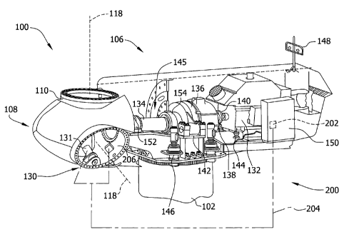
Figure 2 is a cross-sectional perspective view of nacelle 106 of exemplary
wind
turbine 100. Various components of wind turbine 100 are housed in nacelle 106
atop
tower 102 of wind turbine 100. Hub 110 includes a plurality of pitch drive
mechanisms wherein one pitch drive mechanism 130 is coupled to one blade 112
(shown in Figure 1). Pitch drive mechanism 130 modulates the pitch of
associated
blade 112 along pitch axis 118. For the exemplary wind turbine 100 having
three
rotor blades 112, only one of three pitch drive mechanisms 130 is shown in
Figure 2,
wherein each pitch drive mechanism 130 includes at least one pitch drive motor
131.
Pitch drive motor 131 is any electric motor driven by electrical power that
enables
pitch drive mechanism 130 to function as described herein. Alternatively,
pitch drive
mechanism 130 includes any suitable structure, configuration, arrangement,
and/or
component such as, but not limited to, hydraulic cylinders, springs, and
servomechanisms. Moreover, pitch drive mechanism 130 may be driven by any
suitable means such as, but not limited to, hydraulic fluid and/or mechanical
power,
such as, hut not limited to, induced spring forces and/or 'electromagnetic
forces.
Nacelle 106 also includes rotor 108 that is rotatably coupled to an electric
generator
132 positioned within nacelle 106 via rotor shaft 134 (sometimes referred to
as a low
speed shaft), a gearbox 136, a high speed shaft 138, and a coupling 140.
Rotation of
rotor shaft 134 rotatably drives gearbox 136 that subsequently rotatably
drives high
speed shaft 138. High speed shaft 138 rotatably drives electric generator 132
via
coupling 140 and high speed shaft 138 rotation results in the production of
electrical
power by electric generator 132. Gearbox 136 and generator 132 are supported
by
supports 142 and 144, respectively. In the exemplary embodiment, gearbox 136
-6-
CA 02707407 2016-08-02
235088
utilizes a multiple load path gear arrangement to drive high speed shaft 138.
Alternatively, in direct drive configurations, main rotor shaft 134 is coupled
to electric
generator 132.
Nacelle 106 further includes a yaw drive assembly 146 that is used to rotate
nacelle
106 and rotor 108 on axis 116 (shown in Figure 1) to control the perspective
of rotor
blades 112 with respect to the direction of wind 124, as described in more
detail
herein. Nacelle 106 also includes at least one meteorological mast 148. Mast
148
includes a wind vane and anemometer (neither shown in Figure 2). Mast 148
provides information to a turbine control system (not shown) that may include
wind
direction and/or wind speed. A portion of the turbine control system resides
within a
control panel 150. In the exemplary embodiment, nacelle 106 includes forward
support bearing 152 and aft support bearing 154. Alternatively, nacelle 106
may
include any number of shaft and bearing support arrangements that enables wind
turbine 100 to function as described herein. Support bearings 152 and 154
provide
radial support and alignment of rotor shaft 134, as well as enable
transmission of all
loads associated with rotor 108 into tower 102 and ultimately into supporting
surface
104.
Wind turbine 100 includes a pitch control system 200. In one embodiment, at
least a
portion of pitch control system 200 is positioned in nacelle 106.
Alternatively, at least
a portion of pitch control system 200 is positioned outside nacelle 106.
Specifically,
at least a portion of pitch control system 200 described herein includes at
least one
processor 202 and a memory device (not shown), and at least one input/output
(I/O)
conduit 204, wherein I/O conduit 204 includes at least one I/O channel (not
shown).
More specifically, processor 202 is positioned within control panel 150. Pitch
control
system 200 substantially provides a technical effect of wind turbine noise
reduction as
described herein.
As used herein, the term processor is not limited to integrated circuits
referred to in
the art as a computer, but broadly refers to a microcontroller, a
microcomputer, a
programmable logic controller (PLC), an application specific integrated
circuit, and
other programmable circuits, and these terms are used interchangeably herein.
In the
embodiments described herein, memory may include, but is not limited to, a
-7-
CA 02707407 2016-08-02
235088
computer-readable medium, such as a random access memory (RAM), and a
computer-readable non-volatile medium, such as flash memory. Alternatively, a
floppy disk, a compact disc ¨ read only memory (CD-ROM), a magneto-optical
disk
(MOD), and/or a digital versatile disc (DVD) may also be used. Also, in the
embodiments described herein, additional input channels may include, without
limitation, computer peripherals associated with an operator interface, such
as a
mouse and a keyboard. Alternatively, other computer peripherals may also be
used
that may include, without limitation, a scanner. Furthermore, in the exemplary
embodiment, additional output channels may include, without limitation, an
operator
interface monitor.
Processor 202 and other processors (not shown) as described herein process
information transmitted from a plurality of electrical and electronic devices
that may
include, without limitation, blade pitch position feedback devices 206
(described
further below) and electric power generation feedback devices (not shown). RAM
and storage -devices (not shown) store and transfer information and
instructions to be
executed by processor 202. RAM and storage devices can also be used to store
and
provide temporary variables, static and dynamic (i.e.,- non-changing and
changing)
information and instructions, or other intermediate information to processor
202
during execution of instructions by processor 202. Instructions that are
executed
include, but are not limited to, resident blade pitch system 200 control
commands.
The execution of sequences of instructions is not limited to any specific
combination
of hardware circuitry and software instructions.
In the exemplary embodiment, at least a portion of pitch control system 200
including,
but not limited to, processor 202 is positioned within control panel 150.
Moreover,
processor 202 is coupled to blade pitch drive motors 131 via at least one I/O
conduit
204. I/O conduit 204 includes any number of channels having any architecture
including, but not limited to, Cat 5/6 cable, twisted pair wiring, and
wireless
communication features. Pitch control system 200 may include distributed
and/or
centralized control architectures.
Pitch control system 200 also includes a plurality of independent blade pitch
position
feedback devices 206 coupled with processor 202 via at least one I/O conduit
204. In
-8-
CA 02707407 2016-08-02
235088
the exemplary embodiment, each pitch drive mechanism 130 is associated with a
single blade pitch position feedback device 206. Alternatively, any number of
blade
pitch position feedback devices 206 may be associated with each pitch drive
mechanism 130. Therefore, in the exemplary embodiment, pitch drive mechanism
130 and associated drive motor 131, as well as blade pitch position feedback
device
206, are inaluded in system 200 as described herein. Each blade pitch position
feedback device 206 measures a pitch position of each blade 112, or more
specifically
an angle of each blade 112 with respect to wind 124 (shown in Figure 1) and/or
with
respect to hub 110. Blade pitch position feedback device 206 may include any
suitable sensor having any suitable location within or remote to wind turbine
100,
such as, but not limited to, optical angle encoders, magnetic rotary encoders,
and
incremental encoders, or some combination thereof. Moreover, blade pitch
position
feedback device 206 transmits pitch measurement signals (not shown) that arc
substantially representative of associated blade 112 pitch position to
processor 202 for
processing thereof.
Figure 3 is a cross-sectional view of hub 110 illustrating an exemplary pitch
drive
mechanism 130. In the exemplary embodiment, pitch drive mechanism 130 is
operatively coupled to processor 202 (shown in Figure 2) for control thereby,
and
includes at least one pitch actuator 250 having a pitch drive gear 252 and a
pitch ring
gear 254 that are operatively coupled to hub 110 and rotor blades 112. During
wind
turbine operation, pitch actuator 250 changes a pitch -angle of rotor blades
112 by
rotating rotor blades 112 with respect to hub 110, as described in more detail
herein.
More specifically, pitch ring gear 254 is coupled to rotor blade 112 such that
rotation
of pitch drive gear 252 rotates rotor blade 112 about an axis of rotation 256
to thereby
change the pitch of rotor blade 112. In an alternative embodiment, pitch
actuator 250
may include any suitable structure, configuration, arrangement, and/or
components
that enable pitch drive mechanism 130 to function as described herein
including, but
not limited to, electrical motors, hydraulic cylinders, springs, and/or
servomechansims. Moreover, pitch actuator 250 may be driven by any suitable
system including, but not limited to, hydraulic fluid, electrical power,
electro-
chemical power, and/or mechanical power, such as for example, spring force.
-9-
CA 02707407 2016-08-02
235088
In the exemplary embodiment, at a wind velocity of 0 miles per hour (MPH) but
below a cut-in speed, rotor blades 112 are positioned in a fully feathered
position 260,
i.e., fully pitched into the oncoming wind 124, and the generator rotor speed
is equal
to or approximately 0 revolutions per minute (RPM). As the wind velocity
increases
to the cut-in speed, rotor blades 112 are pitched to full operational position
262.
Immediately prior to the cut-in speed, rotor blades 112 will be pitched to an
intermediate position 264 to facilitate reinforcement of the rotor shaft speed
increase,
as described in more detail herein.
Pitch actuator 250 may be driven by energy extracted from rotational inertia
of rotor
108 and/or a stored energy source (not shown) that supplies components of wind
turbine 100, such as, but not limited to, pitch drive mechanism 130, energy
during an
anomaly in the electrical load and/or power source coupled to wind turbine
100. For
example, an anomaly in the electrical load and/or power source may include,
but is
not limited to, a power failure, an undervoltage condition, an overvoltage
condition,
and/or an out-of-frequency condition. As such, the stored energy source
enables
pitching of rotor blades 112 during the anomaly. Although other stored energy
sources may be used, in some embodiments the stored energy source includes
hydraulic accumulators, electrical generators, stored spring energy,
capacitors, and/or
batteries. The stored energy sources may be located anywhere within, on,
adjacent to,
and/or remote from wind turbine 100. In some embodiments, the stored energy
source stores energy extracted from rotational inertia of rotor 108, and/or
other
auxiliary energy sources such as, but not limited to, an auxiliary wind
turbine (not
shown) coupled to wind turbine 100, solar panels, and/or hydro-power
installations.
Figure 4 is a cross-sectional view of an exemplary wind turbine blade assembly
300
suitable for use with the exemplary wind turbine 100 shown in Figure 1. In the
exemplary embodiment, flow separation is inhibited (for example, diminished
and/or
delayed) by a plurality of active flow modification devices 302, such as for
example
blowing or suction flow, piezoelectric synthetic jets or zero net-mass
actuators, other
synthetic jet devices such as dual bimorph synthetic jet (DBSJ) devices, or
any
combination thereof. In an alternative embodiment, non-zero mass flow
actuation
-10-
CA 02707407 2016-08-02
235088
= devices, such as "flip-flop" or alternative jets, fluidic oscillators
that provide pulsed
velocity jets, and blowing or suction flow may be used. =
A flow separation point is represented as being at a position 304 as opposed
to at an
upstream position 306 where it would naturally result without active flow
modification. In the exemplary embodiment, flow separation is inhibited by
introducing a steady or unsteady (time dependent) jet flow 308 having a large
component of momentum and vorticity substantially along the wind flow
proximate to
the blade. Jet flow 308 adds momentum and vorticity in the wind flow proximate
to
the blade in a form of the process known as "shear layer mixing". When
vorticity and
momentum are added by the active flow modification, the momentum deficit of
boundary layers is at least partially re-energized, and the flow separation is
inhibited
and available lift is enhanced. An air flow wherein separation has been
inhibited aids
in adding lift to rotor blade 112, thereby increasing the performance of the
turbine for
a given blade length or reducing the blade chord dimension that may be
required for a
given level of performance. More specifically the =exemplary wind turbine 100
described herein enables reduced chord dimension to be traded for increased
blade
length resulting in increased energy production for the same or lower blade
weight,
i.e., rotor 108 loads imparted to wind turbine 100. Active flow modification
devices
302 may add or subtract momentum and vorticity at particular jet-to-incident
.flow
ratio and specific jet angles relative to the wind flow proximate to rotor
blade 112,
wherein such angles may be varied according to the desired range of
performance
conditions.
Figure 5 is a cross-sectional view of an alternative wind turbine blade
assembly 400
suitable for use with the exemplary wind turbine 100 shown in Figure 1. In the
exemplary embodiment, an active flow modification device 402 promotes flow
separation. - For example, the flow separation point is represented as being
at a
= position 404 as opposed to a downstream position 406 where it would
naturally result
without active flow modification. Flow separation is promoted by introducing a
steady or unsteady jet flow 408 having a large component of momentum
substantially
disruptive to the wind flow proximate to rotor blade 112. The steady or
unsteady jet
flow 408 initiates flow separation in the wind flow proximate to the blade. In
the
-11-
'
CA 02707407 2016-08-02
235088
exemplary embodiment, jet flow 408 may be an oblique jet flow that obstructs
the
natural wind flow proximate to the blade. The promoted flow separation results
in a
decreased lift, and may be advantageously employed to mitigate undesirable
loading
conditions during wind turbine operation. Such undesirable conditions include
cases
of increased wind flow velocity that leads to an increased loading of rotor
blades 112
(increased lift) and attendant effects on wind turbine 100. The embodiments
shown in
Figure 5 and described herein provide for artificially decreasing the lift,
nearly
instantaneously in certain cases, by actively modifying the wind flow
proximate to
rotor blade 112. Active flow modification devices 402 may add disruptive
momentum at a particular jet-to-incident flow ratio and at specific angles to
a wind
flow proximate .to rotor blade 112, and such angles may be varied according to
the
desired range of performance conditions.
Figure 6 is a graph 500 illustrating a wind turbine operational regime 502
wherein
wind turbine blade pitch is varied relative to wind velocity to facilitate
turbine
operation that, in the exemplary embodiment, includes controlling generator
speed
and power production, as described in more detail herein. More specifically,
Figure 6
illustrates a power curve 504 as a function of wind velocity 506, a wind
turbine
generator speed plot 508 as a function of wind velocity 506, and a wind
turbine rotor
pitch plot 510 as a function of wind velocity 506. In the exemplary
embodiment, at a
wind velocity of 0 miles per hour (MPH) 520 but below a cut-in speed .526,
rotor
blades 112 are positioned in a fully feathered position 522, i.e., fully
pitched into the
oncoming wind 124, and the generator rotor speed 524 is equal to or
approximately 0
revolutions per minute (RPM). Alternatively, at a wind velocity slightly
greater than
0 MPH 520, rotor blades 112 may be positioned at an intermediate blade angle
530,
such as for example approximately 24% of the total pitch range from fully
feathered
position 522 to a full operational blade angle 528.
In the exemplary embodiment, as wind velocity increases to cut-in speed 526,
rotor
blades 112 are pitched to full operational position 528 of approximately 0 .
In the
exemplary embodiment, immediately prior to cut-in .speed 526, rotor blades 112
will
be pitched to intermediate position 530 to facilitate reinforcement of the
rotor shaft
speed increase. In an alternative embodiment, rotor blades 112 may not be
pitched
CA 02707407 2016-08-02
=
235088
prior to cut-in speed 526, but may alternatively maintain the fully feathered
position
522 until cut-in speed 526 is reached.
As wind velocity increases beyond cut-in speed 526, a cut-in condition 532 is
achieved and billable power production (i.e., electricity sent to the grid)
commences
534. More specifically, generator 132 begins to produce power 534 which, in
the
exemplary embodiment, is approximately 2% of full generator rating 536 at cut-
in
condition 532, as described in more detail herein. Alternatively, generator
132
produces any amount of power that enables wind turbine 100 to function as
described
herein.
As wind velocity increases to a speed 538 such that the generator 132 reaches
a rated
speed 540, rotor blade pitch continues to be maintained 542 at full
operational mode,
i.e., approximately 0 pitch configuration. In the exemplary embodiment,
between
wind velocity 532 and wind velocity 538, power production 544 increases
substantially with the cube of the wind velocity until the wind velocity
facilitates
increasing the generator speed to a point 546 that signifies rated power level
536 of
wind turbine 100. In the exemplary embodiment, at a wind velocity 550 rotor
blades
112 start to be pitched 552 towards feathered such that power production is
maintained at the rated power level 536. In an alternative embodiment, rotor
blades
112 may be trimmed in a peak shaver mode 554 to facilitate reducing the wind
turbine
loads prior to reaching rated power level 536 of the wind turbine. More
specifically,
while in peak slaver mode 554, rotor blades 112 are trimmed gradually towards
the
feathered configuration 556 prior to reaching rated power level 536 of wind
turbine
100.
As the wind speed reaches a cut-out speed 560, rotor blades 112 are trimmed to
the
fully feathered configuration 562 (equivalent to fully feathered position 522)
and
generator 132 reaches a cut-out condition 564, wherein power generation and
generator speed are reduced to approximately 0, denoted by point 566. Such a
configuration protects wind turbine 100 against damage to wind turbine
components
due to exceeding mechanical loads (forces and moments) and torque limitations
for
such components.
-13-
CA 02707407 2016-08-02
235088
Figure 7 is a graph 600 illustrating a wind turbine operational regime 602
using an
active flow control (AFC) device, such as for example active flow modification
device 302 shown in Figure 4, wherein wind turbine blade pitch is varied
relative to
the wind velocity to facilitate wind turbine operation that includes
controlling
generator speed in region 679 in coordination with power production, as
described in
more detail herein. More specifically, Figure 7 illustrates a power curve 604
as a
function of wind velocity 606, a wind turbine generator speed plot 608 as a
function
of wind velocity 606, a wind turbine rotor pitch plot 610 as a function of
wind
velocity 606, and an AFC device operational magnitude plot 612 as a function
of wind
velocity 606. In the exemplary embodiment, at a wind velocity of approximately
0
miles per hour (MPH) 620, rotor blades 112 are positioned in a fully feathered
configuration 622, i.e., fully pitched into the oncoming wind 124, and a
generator
rotor speed 624 is equal to or approximately 0 revolutions per minute (RPM).
Alternatively, at a wind velocity slightly above 0 MPH 620 (but below a cut-in
speed
626), rotor blades 112 may be positioned at an intermediate blade angle 630,
such as
for example approximately 24% of the total pitch range from fully feathered
position
622 to full operational blade angle 628.
In the exemplary embodiment, as wind velocity increases to a cut-in speed 626,
rotor
blades 112 arc pitched to a full operational position 628 of approximately 0 .
In the
exemplary embodiment, immediately prior to cut-in speed 626, rotor blades 112
will
be pitched to an intermediate position 630 to facilitate reinforcement of the
rotor shaft
speed increase. In an alternative embodiment, rotor blades 112 may not be
pitched
prior to cut-in speed 626, but may alternatively maintain a fully feathered
configuration 622 until cut-in speed 626 is reached.
As wind velocity increases beyond cut-in speed 626, a cut-in condition 632 is
achieved and billable power production (i.e., electricity sent to the grid)
commences
634. More specifically, generator 132 begins to produce power 634 which, in
the
exemplary embodiment, is approximately 2% of full generator rating 636 at cut-
in
condition 632, as described in more detail herein. Alternatively, generator
132
produces any amount of power at cut-in condition 632 that enables wind turbine
100
to function as described herein.
-14-
CA 02707407 2016-08-02
235088
As wind velocity increases beyond cut-in condition 632 the generator RPM speed
increases substantially linearly 637 therewith, and at an activation wind
speed 638, an
active flow control (AFC) device is activated 639. More specifically, and in
the
exemplary embodiment, at activation wind speed 638 the AFC device is activated
639
at a minimum or substantially minimum setting 640, as described in more detail
herein. Substantially
simultaneously with activation 639 of the AFC device,
processor 202 adjusts rotor blades 112 slightly towards feathered position
641, such as
for example 5%-10% of full feathered position, to facilitate a smooth
transition of the
generator speed in reaching a generator rated speed 642. In an alternate
embodiment,
utilizing a different blade design, the foregoing pitch adjustment may be
opposite and
slightly beyond the operational position (i.e., away from feathered).
Following
activation 639 of the AFC device, generator speed slightly decreases 644 as a
function
of the specific blade design, change in pitch and the parasitic power
requirements
associated with the AFC device activation 639. As wind speed increases beyond
activation wind speed 638, generator speed reaches a minimum AFC transition
point
646 and increases 648 therefrom as a function of an increase in an AFC device
setting
650. The pitch setting is maintained 652 at an angle below the full
operational angle,
as described herein.
In the exemplary embodiment, as wind velocity increases beyond the minimum AFC
transition point 646 to a speed 654, generator 132 reaches generator rated
speed 642,
and rotor blade pitch continues to be maintained 652 at an angle less than
full
operational position 628, as described herein. In an alternate embodiment,
utilizing a
different blade design, the foregoing pitch adjustment may be opposite and
slightly
beyond operational position (i.e., away from feathered or greater then the
full
operational position). The AFC device is increased to a fully activated
configuration
658 to facilitate increasing lift while substantially prohibiting airflow
separation from
rotor blade 112. In an alternative embodiment, the AFC device may be
continuously,
linearly or non-linearly increased 660 to a full-on configuration, or stepped
in pre-
determined increments in any combination thereof to the full-on configuration.
As wind velocity increases beyond speed 654 to a speed 662, generator speed is
maintained at a rated speed 664, while rotor blade pitch is trimmed towards a
full
-15-
CA 02707407 2016-08-02
235088
operational position 666 of approximately 0" to maintain the power generation
in
accordance with power curve 604. In the exemplary embodiment, as wind velocity
increases beyond speed 662, rotor blades 112 are trimmed in a peak shaver mode
668
in combination with a decrease in AFC device operations 670 to facilitate
reducing
the wind turbine loads prior to reaching a rated power level 672 of wind
turbine 100.
More specifically and in the exemplary embodiment, while in peak shaver mode
668,
rotor blades 112 are trimmed gradually towards feathered configuration 674
subsequent to reaching rated power level 672 of wind turbine 100 substantially
simultaneously with decreasing AFC device operations 670 as the power
generation
approaches rated power level 672.
As the wind velocity 606 continues to increase towards a cut-out speed 680,
the AFC .
device is disabled 682, rotor blades 112 are progressively trimmed towards the
fully
feathered configuration 622 and the generator speed reaches a cut-out
condition 684,
wherein power generation and generator speed are reduced to approximately 0,
denoted by point 686. Such a configuration protects wind turbine 100 against
damage
to wind turbine components due to exceeding mechanical loads (forces &
moments)
and torque limitations for such components.
Exemplary embodiments of active flow control systems and operation strategies
are
described in detail above. The above-described methods for implementing such
active
flow control systems facilitate effective use of the AFC, device. More
specifically, the
systems and methods described herein combine substantially uniform AFC
operations
with rotor blade pitch control to facilitate mitigating uniform and non-
uniform rotor
scale events (i.e., wind gusts), wind shear events, and local noise generation
events by
increasing and decreasing lift on the rotor blades. Such strategies provide
maximum energy production with low parasitic power consumption typically
required to power the AFC device over the range of turbine operating
conditions.
Use of such an AFC system further facilitates providing a rotor blade with a
reduced
chord length over at least a portion of the rotor blade, in turn enabling
increased
blade length (i.e., increased rotor swept area) with attendant increase in
energy
production without increasing loads and improving blade efficiency over a
broader
-16-
=
CA 02707407 2016-08-02
235088
range of operating conditions. Such a configuration facilitates increasing a
total
value of the wind turbine system while reducing cost of energy production.
While the apparatus and methods described herein are described in the context
of
methods for implementing active flow control systems on wind turbine blades,
it is
understood that the apparatus and methods are not limited to wind turbine
applications. Likewise, the system components illustrated are not limited to
the
specific embodiments described herein, but rather, system components can be
utilized independently and separately from other components described herein.
As used herein; an element or step recited in the singular and proceeded with
the
word "a" or "an" should be understood as not excluding plural elements or
steps,
unless such exclusion is explicitly recited. Furthermore,
references to "one
embodiment" of the present invention are not intended to be interpreted as
excluding
the existence of additional embodiments that also incorporate the recited
features.
This written description uses examples to disclose the invention, including
the best
mode, and also, to enable any person skilled in the art to practice the
invention,
including making and using any devices or systems and performing any
incorporated
methods. The patentable scope of the invention may include other examples that
occur to those skilled in the art in view of the description. Such other
examples are
intended to be within the scope of the invention.
=
-17-
.