Note: Descriptions are shown in the official language in which they were submitted.
CA 02707793 2015-07-08
ENERGY RECOVERY ENHANCED CONDENSER REACTIVATED
DESICCANT REFRIGERANT DEHUMIDIFIER
Field of the Invention
[0002] The present invention relates to air conditioning and dehumidification
equipment, and more particularly to an air conditioning method and apparatus
using desiccant dehumidification technology.
[0003] It is well known that traditional cooling coil based air conditioning
systems do not provide efficient means of dehumidification. Because such
systems must provide cooling in order to provide dehumidification, in many
cases the cooling is in excess of what is required and the desired enclosure
or
space is over cooled. If insufficient cooling is supplied the space to be
cooled
will be under dehumidified. To overcome this problem, reheat coils have been
used downstream of the dehumidifying cooling coil. This allows the cooling
coil
to dehumidify as needed and the reheat coil to then raise the supply air
temperature to avoid supplying over cooled air to the enclosure. This method
is
CA 02707793 2010-06-02
WO 2009/102910
PCT/US2009/033988
- 2 -
inefficient because energy is utilized to lower the air temperature and then
more
energy is utilized to raise the temperature back up.
[0004] Due to their inefficiency ASHRAE standard 62-1989 has precluded the
use of reheat devices in air conditioning systems unless the heat is recovered
from the site. In addition, ASHRAE standard 62-1989 requires that systems with
larger air flows must use some form of exhaust energy recovery to minimize the
amount of energy used to condition outside air being introduced to the space.
[0005] A number of commercially available systems have been developed that
combine energy recovery, pre-treatment, with cooling coil dehumidification and
site recovered reheat. One such system is shown in Figure 1 wherein an energy
recovery ventilator with a packaged DX cooling and condenser reheat system is
illustrated. An energy recovery ventilator generally consists of an enthalpy
wheel
of known construction which transfers both heat and sensible energy between
two
air streams. Enthalpy wheels are commonly used to transfer outgoing
temperature and humidity (energy) to incoming ambient air. These energy
exchangers are generally made of porous materials to increase surface area
which
aids in energy transfer. Other forms of energy transfer systems, such as heat
pipes, can also be used.
[0006] In the system shown in Figure 1, a fresh or outdoor supply of air
(ambient
air) is passed through a segment of the energy recovery device (in this case
an
enthalpy wheel) to reduce the supply air's humidity and temperature. The
supply
air is then passed through an evaporator/cooling coil of a conventional
refrigeration system to reduce its humidity and temperature further. The
dehumidified and cooled air is then passed through the condenser coil of the
refrigeration system to raise the supply air temperature. The thus
dehumidified
and warm air is then supplied through a duct system directly to the desired
space.
[0007] In the Figure 1 system, exhaust air is drawn from the space with a fan
or
blower (not shown) and passed through a separate segment of the enthalpy wheel
energy recovery device. As a result the temperature and humidity of the
exhaust
air stream is increased and then the exhaust is rejected to the atmosphere.
This
type of prior art device is effective in reducing the moisture in the supply
air and
utilizes energy recovery, but requires significant cooling to obtain the
desired
CA 02707793 2010-06-02
WO 2009/102910
PCT/US2009/033988
- 3 -
dehumidification performance. Much of the energy utilized to cool the air to
obtain this dehumidification is reversed through the heating coil to eliminate
over
cooling of the space.
[0008] Figure 2 is a psychrometric diagram of the system in Figure 1 and
provides the psychrometric analysis of the effects of each component of the
system on the supply air.
[0009] In this illustrative system the ambient or outside air (OA) has a
humidity
ratio of about 100 grub and a temperature of about 94 F; after leaving the
energy
recovery wheel it has a humidity ratio of about 80 gr/lb and a temperature of
about 83 F; after passing through the evaporator coil it has a humidity ratio
of
about 59 grub and temperature of about 53 F and, after leaving the condenser
coil has the same humidity ratio, about 59 grub and a temperature of about 72
F.
[0010] Another form of condenser regenerated conditioning system is shown in
Figure 3 and also in Figure 7 of US Pat. No. 6,557,365 B2. That system uses a
DX cooling coil to cool and dehumidify ambient/outside air prior to entering a
desiccant wheel. The air is then dehumidified further and heated with the
desiccant wheel before being supplied to the space. A separate ambient air
stream is used as the regeneration air stream and is first heated utilizing
condenser heat from the DX refrigeration cycle; the thus heated air stream is
then
used to drive moisture off of the desiccant wheel. The regeneration air stream
collects the moisture and rejects it to the atmosphere. Many other desiccant
dehumidification systems are commercially available that utilize other sources
of
heat to regenerate desiccant wheels to provide dehumidification and heating
cycles to supply air. The vast majority of these devices require high
regeneration
temperatures to regenerate the desiccant.
[0011] Figure 4 shows the psychrometric diagram for the system of Figure 3 and
shows the effect of the system components on the supply air system. As seen
therein the outside air supplied to the evaporator coil has a temperature of
about
93 F and humidity ratio of about 100 gr/lb. After leaving the evaporator coil
it
has a temperature of about 62 and humidity ratio about 78 gr/lb. Upon leaving
the desiccant wheel it has a temperature of about 72 F and a humidity ratio of
about 58 gr/lb.
CA 02707793 2010-06-02
WO 2009/102910
PCT/US2009/033988
- 4 -
[0012] Figure 5 illustrates another prior art air conditioning system which,
in this
case, uses a condenser regenerated desiccant system with enthalpy recovery pre-
treatment of the supply air. As seen therein, fresh outdoor ambient supply air
is
passed through a sector of an enthalpy recovery device, dehumidified and
cooled
and then passed through the cooling coil of a conventional DX refrigeration
system further reducing its humidity and temperature. The thus cooled and
dried
supply air stream is then passed through a desiccant device in which it is
dehumidified, heated and thereafter supplied to the space via a duct system.
Exhaust air is drawn from the space with a fan or blower (not shown) and
passed
through another section of the enthalpy recovery device in which the exhaust
air
is heated and humidified and then rejected to the atmosphere. In this system,
a
separate air stream from the ambient is heated utilizing the condenser coil
from
the refrigeration system and is then used as the regeneration air stream. The
regeneration air stream is passed through another section of the desiccant
device,
cooled and humidified, and then rejected to the atmosphere.
[0013] Figure 6 shows the psychrometric diagram of the system of Figure 5 and
shows the effects of each component of the system on the supply air. As seen
therein, the outside supply air initially has a humidity ratio of about 100
gr/lb and
temperature of about 93 F; after passing through the enthalpy wheel the supply
air has a humidity ratio of about 84 grub and a temperature of about 84 F.
After
passing through the evaporator coil it has a humidity ratio of about 78 gr/lb
and a
temperature of about 62 F. After passing through the desiccant wheel it has a
humidity ratio of about 58 gr/lb and temperature of about 72 F as it is
supplied to
the space.
SUMMARY OF THE INVENTION
[0014] As compared to conventional air conditioning systems and processes as
described above the present invention has significant advantages in treating
fresh
or outdoor air to supply that air at space temperature and at or below space
humidity. The most significant advantage is low energy consumption. More
specifically, the present invention reduces the required energy input from 30
to
75% as compared to the other techniques available.
CA 02707793 2010-06-02
WO 2009/102910
PCT/US2009/033988
- 5 -
[0015] An additional significant benefit of the invention is the ability to
provide
lower supply air humidity conditions (dew point or grAb (absolute humidity
ratio)) than some other techniques. More particularly, coil based dehumidifier
systems have problems with ice forming on the evaporator coils as they provide
lower coil temperatures in order to provide lower humidity conditions. The
present invention on the other hand provides the ability to provide lower
supply
air humidity conditions (dew point or gr/lb) by utilizing a desiccant based
dehumidification cycle after the cooling coil.
[0016] It is an object of the present invention to treat outdoor or fresh,
ambient
supply air and dehumidify and cool that air from the outdoor ambient condition
to
the desired space air condition. ASHRAE has defined the comfort conditions for
a building to be between 73 F and 78 F temperature and about 50% relative
humidity or 55 gr/lb of air to 71 gr/lb of air. In particular the present
invention is
particularly suited to treat hot and humid air in the southeastern United
States and
other hot and humid climates around the world with ambient air conditions
ranging from 60 F to 105 F or more and a moisture content of 70 to 180 gr/lb
and deliver the treated air to the space temperature, and at or below the
space
humidity, generally in the range of about 70 F to 85 F and a moisture level of
about 45 to about 71 gr/lb. Ranges somewhat lower and higher than those
proposed by ASHRAE can also be achieved by this invention when design space
conditions vary from stated ASHRAE conditions.
[0017] Another object of the present invention is to provide such treatment of
outdoor, fresh, ambient air very efficiently with lower energy input than most
treatments systems currently available.
[0018] Yet another object of the present invention is to provide a system that
can
provide varying capacity of dehumidification and cooling to react to and
overcome varying cooling and dehumidification loads of the fresh or outdoor
supply air and/or the building itself.
[0019] A further object of the present invention is to provide heating to the
outdoor or fresh supply air with the use of an energy recovery device during
cold
weather periods to lower the heating input requirement to heat air to the
space
temperature condition. More specifically, the system utilizes exhaust air with
CA 02707793 2010-06-02
WO 2009/102910
PCT/US2009/033988
- 6 -
heat transferred to fresh or outdoor supply air with an energy recovery heat
exchanger to substantially increase the temperature and/or the humidity of the
air
prior to being heated by a heating device. Thus, a temperature as such as -10
F
would be heated to approximately a temperature of 50 F or higher as needed.
[0020] In accordance with one aspect of the invention an air conditioning
system
includes a means for recovering energy from an exhaust air stream by passing
the
exhaust air stream across an energy recovery device such as an enthalpy wheel.
Fresh, outdoor, ambient supply air is passed over the other "side" of the
energy
recovery device. The energy recovery device transfers energy from one air
stream to the other without air transferring across the device. This allows
for a
reduction in temperature and, in some devices, reduction in humidity in the
supply air when the ambient condition is warmer and more humid than the space
condition. It also allows for the increase in temperature and, in some
devices, the
increase of humidity in the supply air when the ambient condition is colder
and
dryer than the space condition.
[0021] In accordance with another aspect of the invention the system of the
present invention utilizes a cooling coil to lower the temperature and
humidity of
the supply air before supplying it to the space at which it is required. A
desiccant
dehumidification device that utilizes reactivation heat from a refrigeration
system
provides additional dehumidification while increasing the temperature of the
supply air. Additional cooling of the air is an option to provide lower
temperature supply air and overcome internal building sensible load if
desired.
[0022] Systems according to the present invention can also utilize the exhaust
air
that has passed through an energy recovery device to provide the reactivation
air
source for the desiccant dehumidification cycle. A condenser coil from a
conventional refrigeration system is utilized to increase the temperature of
the
exhaust air and then passes this air through another segment of the desiccant
device to provide regeneration of the desiccant device. The exhaust air stream
is
cooled and humidified during this regeneration process and allows it to be
passed
through an additional condenser coil to receive additional heat rejected from
the
refrigeration system. An evaporate cooling device can also be added prior to
the
second condenser coil to lower the exhaust air entering the second condenser
coil
CA 02707793 2010-06-02
WO 2009/102910
PCT/US2009/033988
- 7 -
to improve the refrigeration systems efficiency and/or increase the capacity
of the
heat rejection of the condenser.
[0023] The above, and other objects, features and advantages of the present
invention will be apparent in the following detailed description of
illustrative
embodiments thereof which is to be read in connection with the accompanying
drawings, wherein:
BRIEF DESCRIPTION OF THE DRAWINGS
[0024] Figure 1 is a schematic diagram of a conventional prior art energy
recovery air conditioning or ventilator, using a DX cooling and condenser
reheat
system;
[0025] Figure 2 is a psychrometric chart describing the effects of the
components
of the system on the supply air stream of the system shown in Figure 1;
[0026] Figure 3 is a schematic diagram of a prior art condenser reactivated
desiccant system;
[0027] Figure 4 is a psychrometric chart describing the effects of the system
components on the supply air stream of the system shown in Figure 3;
[0028] Figure 5 is a schematic diagram of a prior art condenser reactivated
desiccant system using an enthalpy energy recovery pre-treatment system;
[0029] Figure 6 is a psychrometric chart describing the effects of the system
components on the supply air stream shown in Figure 5;
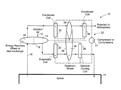
[0030] Figure 7 is a schematic view of an air conditioning system according to
the present invention;
[0031] Figure 8 is a psychrometric chart showing the effects of the components
on the supply air stream in the system shown in Figure 7;
[0032] Figure 9 is a psychrometric chart showing the effects of the components
on the exhaust air stream in the system shown in Figure 7;
[0033] Figure 10 is a schematic illustration of a second embodiment of the
present invention;
[0034] Figure 11 is a psychrometric chart showing the effects of the
components
on the exhaust air stream in the system shown in Figure 10;
CA 02707793 2010-06-02
WO 2009/102910
PCT/US2009/033988
- 8 -
[0035] Figure 12 is a schematic illustration of a third embodiment of the
invention;
[0036] Figure 13 is a schematic illustration of a fourth embodiment of the
invention;
[0037] Figure 14 is a schematic illustration of a fifth embodiment of the
invention;
[0038] Figure 15 is a schematic illustration of a sixth embodiment of the
invention;
[0039] Figure 16 is a schematic illustration of a seventh embodiment of the
invention; and
[0040] Figure 17 is a schematic illustration of an eighth embodiment of the
invention.
DETAILED DESCRIPTION
[0041] Referring now to the drawing in detail and initially to Figure 7, an
air
conditioning system 10 according to one embodiment of the invention is
illustrated in which a stream of ambient air 12 is treated to desired
temperature
and humidity conditions for use in a room, enclosure or space 14. In the
illustrative embodiment, the system is used in areas where the ambient outside
air
has a high temperature and high humidity content or ratio as described above.
Figure 7 is a schematic drawing and it will be understood by those skilled in
the
art that the described air streams are contained in appropriate duct work and
moved with appropriate fans, which are not illustrated.
[0042] As seen in Figure 7, fresh, outdoor, ambient supply air 12 is first
passed
through a section 13 of an energy recovery device 16. The air is cooled and
dehumidified as it passes through the energy recovery device 16. As described
above, this device may be a conventional rotating enthalpy wheel or other form
of heat exchanger, such as a heat pipe, to exchange heat between the supply
air
stream 12 and an exhaust air stream 18 drawn from space 14. In the case of
using
a heat pipe the ambient air will be cooled but not dehumidified.
[0043] The cooled and dehumidified supply air stream is then passed through
the
cooling or evaporator coil 20 of a conventional DX refrigerant unit 22, which
CA 02707793 2010-06-02
WO 2009/102910
PCT/US2009/033988
- 9 -
includes a compressor 23, to further reduce its temperature and humidity. The
supply air then passes through a segment of a desiccant device 26, such as a
conventional silica coated rotating corrugated desiccant wheel, to further
reduce
its humidity while increasing its temperature. At this point the supply air is
at or
close to the desired temperature in space 14 and is equal to or below the
desired
humidity in that space.
[0044] When the supply air on leaving desiccant wheel 26 has a humidity ratio
less than that desired in space 14 the supply air will provide
dehumidification
capacity to the space to overcome internal latent load. The supply air can be
directly supplied to the space at that point or it can be further cooled using
an
optional cooling or evaporator coil 28 between the desiccant wheel and space
14
to provide cooling effect to the space and overcome internal sensible load.
[0045] The exhaust air stream 18 is drawn from the space 14 with a fan or
blower (not shown), and then passed over another section 30 of energy recovery
device 16. The exhaust air is heated by the heat absorbed in section 13 and
humidified as it passes through section 30 and then is passed through a
condenser
coil 32 of the refrigeration system 22 to increase its temperature. The
exhaust air
leaving condenser 32 is at a higher temperature than when it entered and is
then
utilized to regenerate the desiccant of wheel 26 by passing the exhaust air
through
a separate section 34 of the desiccant device. The exhaust air stream is
cooled
and humidified during this regeneration process. The now cooler exhaust air
can
then be used to pass over a second condenser coil 36 in system 22 to recover
still
more from the refrigeration system and then is rejected to the atmosphere.
[0046] As will be appreciated by those skilled in the art the system of the
present
invention utilizes the exhaust air stream to recover heat from the ambient
supply
air stream and to regenerate the desiccant wheel. It is also used to recover
or
absorb heat from the refrigeration system through the condensers 32 and/or 36.
This heat rejection potential of the exhaust air stream is increased by the
evaporative cooling effect in the desiccant regeneration process. This
exhaust/regeneration air stream 18 can be equal to or less than the supply air
stream in volume, as desired, using appropriate controls. This is an important
aspect as it is well known that prudent air conditioning design calls for
positive
CA 02707793 2010-06-02
WO 2009/102910
PCT/US2009/033988
- 10 -
air pressure in a building. To obtain positive air pressure, the fresh or
outdoor
supply air quantity must be equal to or larger than the exhaust air quantity.
[0047] Figure 8 is a psychrometric chart which shows the effect of the
components of the invention illustrated in Figure 7 on the supply air stream
12.
As seen therein the effects are similar to those achieved in the prior art
device of
Figure 5, although the present invention allows for the inclusion of an
additional
cooling coil 28 for treating the supply air stream after it leaves the
desiccant
wheel 26. However, unlike the Figure 5 system the present invention recaptures
heat wasted in the exhaust air stream of the Figure 5 system. Thus, the
exhaust
air stream leaving space 14 and entering segment 30 of enthalpy wheel 16 has a
temperature of about 72 F and a humidity ratio of about 64 gr/lb, on leaving
the
enthalpy wheel it has a temperature of about 83 F and a humidity ratio of 80
gr/lb. As it passes through the condenser coil 32 the exhaust air stream
absorbs
the heat rejected from the coil so that when it leaves the coil and enters the
regeneration segment 34 of the desiccant wheel it has a temperature of about
108 F and humidity ratio of 80gr/lb. After passing through the desiccant wheel
segment 34 and before entering the condenser coil 36 the exhaust air stream
has a
temperature of about 80 F and a humidity ratio of about 122 gr/lb. When
passing
through condenser coil 36 it absorbs heat rejected by that coil and its
temperature
rises to about 108 F or more before being discharged to the atmosphere.
[0048] Figure 10 illustrates another embodiment of the invention shown in
Figure 7 and the same reference numerals are used to identify like parts. In
this
embodiment an evaporative cooling device 38 is added between desiccant wheel
26 and the second condenser coil 36 in the exhaust air stream. The evaporative
cooling device may be of conventional construction using, for example, cross
corrugated sheet materials of known construction through which a supply of
water is passed cross or countercurrent to the air steam to cool the air
stream.
This additional evaporative cooling of the exhaust air stream further lowers
its
temperature. The exhaust stream at that lower temperature has additional heat
rejection capacity when it enters condenser coil 36 and thus allows for lower
and
more efficient condenser temperatures and lower refrigerant head pressure.
CA 02707793 2010-06-02
WO 2009/102910
PCT/US2009/033988
- 11 -
[0049] Figure 11 is a psychrometric chart showing the effects of the invention
as
illustrated in Figure 10. As a result of the use of the evaporative cooling
device
added between the desiccant wheel 26 and second condenser 36 the exhaust air
stream temperature is reduced further to about 77 F and its humidity ratio
increased to about 130 gr/lb to provide additional cooling and lower
temperature
upon entering the second condenser.
[0050] The present invention provides significant advantages over prior art.
The
use of a single air stream for exhaust, regeneration and condenser heat
rejection
significantly lowers the required fan horsepower (for moving various air
streams)
to accomplish these three tasks. While the system does require increased total
static pressure to overcome the different heat exchangers, the total airflow
is
substantially reduced. As fan power is proportional to the square of the
static
pressure and the cube of the airflow, reduced airflow is a more important
factor in
reducing fan power requirements.
[0051] In addition, the use of a single air stream to provide these functions
also
provides lower humidity levels to the desiccant wheel for the reactivation
process. Building exhaust air is taken from the space at space humidity. It
then
goes through an energy recovery device. This device either does not increase
its
humidity (when using a sensible heat recovery device) or it increases it some
proportion between the outdoor condition and the indoor condition based on the
efficiency of the enthalpy recovery device. In either case the humidity
leaving
the energy recovery device and entering the desiccant wheel is lower than the
outdoor condition. The temperature of the exhaust air is at the same
temperature
regardless of humidity. The temperature is determined by the exhaust recovery
process where temperature exchange is independent of humidity level and the
added condenser heat, again independent of humidity. As the desiccant wheel
acts as a relative humidity exchanger, a lower humidity condition in an air
stream
with determined temperature provides a lower relative humidity. Thus the lower
humidity in the air gives the desiccant device increased capacity through
enhanced regeneration.
[0052] Further advantages of the invention over the prior art are related to
the
refrigeration cycle condenser heat rejection capacity and temperature.
Condenser
CA 02707793 2010-06-02
WO 2009/102910
PCT/US2009/033988
- 12 -
heat must be rejected to the atmosphere. The temperature of the exhaust air
stream of the present invention is lower than the ambient temperature. Just as
with the humidity relationship, the exhaust air is taken from the space and
run
through an energy recovery device. Its temperature is increased at some
fraction
of the difference between the space temperature and the outdoor temperature.
The leaving temperature is at some temperature lower than the outdoor ambient.
This provides two benefits. First the airflow rate required to reject the heat
from
the condenser coil to the air stream is reduced due to its lower temperature
and
the greater difference between the refrigerant temperature entering the
condenser
and the air temperature entering the condenser. The reduced air flow
requirement
also lowers the fan horsepower requirement. It is to a certain extent included
in
the reduced air flow requirement discussed above. In addition, the lower
entering
air temperature to the condenser allows for a lower refrigeration temperature
leaving the condenser and provides a lower head pressure. As the head pressure
lowers, the amount of work the compressor must do to raise the pressure of the
refrigerant is reduced allowing the compressor to operate with a lower power
requirement.
[0053] Yet another enhancement of the present art is the ability and
efficiency of
the exhaust air stream to reject more heat in the second condenser. The
evaporative cooling effect of the desiccant wheel lowers the temperature back
to
a temperature that allows the same air stream to perform more heat rejection.
This again reduces total airflow and provides reduced fan horsepower. The
addition of an evaporative cooling device before this second condenser further
lowers that temperature to provide the same efficiency for the second
condenser
as discussed above for the first condenser. It gives the second condenser the
ability to reject more heat to a smaller air stream and save fan power. It
also
lowers the temperature and reduces head pressure in the refrigerant circuit
reducing compressor power.
[0054] In addition to the above further efficiencies can be achieved when a
desiccant wheel is used as the desiccant device 26 since the speed of rotation
of
the wheel can be controlled to increase or decrease heating and
dehumidification
to control supply air steam temperature and humidity.
CA 02707793 2010-06-02
WO 2009/102910
PCT/US2009/033988
- 13 -
[0055] Figures 12-14 illustrate other embodiments of the invention as shown in
Figure 10, again using the same reference numerals for corresponding parts. In
each embodiment one or more air stream bypasses are provided using
conventional duct work, baffles and controls to selectively bypass a portion
of
one or both of the air streams around the desiccant wheel.
[0056] Figure 12 illustrates the use of a bypass 42 to direct a portion of the
supply air stream around the dehumidification section of desiccant wheel 26.
[0057] Figure 13 illustrates the use of the bypass 42 along with a bypass 44
which bypasses a part of the exhaust air stream around the regeneration
section
34 of the desiccant wheel.
[0058] Figure 14 simply illustrates the use of the single bypass 44 at the
regeneration section 34 of the desiccant wheel.
[0059] Providing one or more such bypasses around a desiccant wheel allows for
several advantages. Modulating the bypass on either the supply or regeneration
side provides capacity modulation of the desiccant effect on the supply air
stream. In addition, the pressure drop of the desiccant wheel can be avoided
during times when dehumidification is not required, allowing for reduced fan
power requirements and more efficient operation. It also allows for greater
flexibility in unit design, providing the ability for the unit to supply more
air than
the desiccant wheel can accommodate. This flexibility can lower the cost of
the
equipment to meet specific unit performance requirements.
[0060] Figure 15 is another embodiment of the invention as shown in Figure 10,
again with similar parts identified with the same reference numerals.
[0061] In this embodiment the condensate from evaporator coil 20 is recovered
in a sump 50 or the like and supplied to the evaporative cooler by a pump 52.
Recovering the condensate for evaporative cooling requirements allows for
increased efficiency without the need for make up water. This will also
achieve
lower water usage costs and lower installation cost.
[0062] Figure 16 is yet another variant on the invention as described above
with
respect to Figure 7. In this embodiment the configuration of the duct work
relative to the desiccant wheel is rearranged so that the ambient/supply air
stream
flows through the desiccant wheel in a direction opposite to the flow of the
CA 02707793 2010-06-02
WO 2009/102910
PCT/US2009/033988
- 14 -
e)thaust/regeneration air stream rather than in the same direction shown in
Figure
7. This counter flow arrangement provides greater desiccant performance for
greater efficiency. The physical layout of this arrangement is more difficult
to
build than the other embodiments and potentially would require more cost. All
other previous indicated embodiments shown in the other figures can also be
added to this embodiment to provide many options and variations of the present
invention.
[0063] Although illustrative embodiments of the present invention have been
described herein with reference to the accompanying drawings, it is to be
understood that the invention is not limited to those precise embodiments, but
that various changes and modifications can be effected therein by those
skilled in
the art without departing from the scope or spirit of this invention.