Note: Descriptions are shown in the official language in which they were submitted.
CA 02707854 2010-06-03
WO 2009/074559
PCT/EP2008/067083
- 1 -
US ED CAPSULE OR POD RECEPTACLE FOR
LIQUID FOOD OR BEVERAGE MACHINES
Field of the Invention
The field of the invention pertains to used capsule
or pod receptacles of machines for preparing liquid food
or beverages from an ingredient of the liquid food or
beverage supplied within a capsule or pod to the machine.
Background Art
Liquid food or beverage preparation machines are
becoming very popular whether at home or in offices. For
instance, there are machines for the preparation of
beverages such as coffee, tea, soup or other similar
beverages, in which at least one ingredient of the
desired beverage, for example ground coffee, is supplied
within a capsule or pod into a capsule or pod extraction
chamber of the machine.
The use of capsules or pods, such as plastic and/or
aluminium-based capsules or pods for the preparation of
beverages has many advantages. Capsules or pods, in
particular aluminium-based capsules or pods, are hermetic
or gas tight and thus can protect the beverage ingredient
effectively during an extended period of time against the
environment such as air, humidity or light, before use of
the ingredient. Thus such capsules and pods prevent
premature degradation of the ingredient. Furthermore,
capsules or pods of a beverage ingredient are easy to
handle, hygienic, and their use involves less cleaning of
the beverage preparation machine, in particular no
significant part of the machine's extraction chamber
comes into contact with the beverage ingredient contained
in the capsule or pod during the extraction process.
Capsules or pods are usually inserted individually
into the machine's extraction chamber, manually or
automatically from a capsule or pod stack. Hot or cold
CA 02707854 2010-06-03
WO 2009/074559
PCT/EP2008/067083
- 2 -
water is then passed through the capsule or pod for
brewing or otherwise extracting the ingredient(s)
contained within the capsule or pod and form the desired
beverage. The prepared beverage is supplied via an outlet
of the machine into a cup, mug or other receptacle to the
user.
Used capsules or pods may either be removed
individually from the liquid food or beverage preparation
machine after each preparation cycle or they may be
collected in a machine's used capsule or pod receptacle
for instance as mentioned in EP 1 731 065.
Typically, the capsule or pod receptacle is located
underneath the capsule or pod chamber so that the
capsules or pods may fall by gravity into the receptacle
upon extraction. In the latter case, the receptacle has
to be emptied by the user when full. The receptacle may
be a drawer-type removable receptacle located in a seat
of the beverage preparation machine typically under the
extraction chamber. The used capsule or pod receptacle
may be slid in and out of the machine's housing.
A problem may arise with such capsule or pod
receptacles, in particular in conjunction with rigid
capsules or pods, when used capsules or pods accumulate
in the receptacle to form a heap of capsules or pods
whose top extends above the receptacle in such a manner
to come into conflict with the housing when the
receptacle is slid out of the machine's housing for
emptying.
A solution to avoid the jamming of the receptacle by
used capsules or pods is to provide an optical level
detector for measuring the level of capsules or pods in
the used capsule or pod receptacle and inviting the user
to empty the receptacle when the level of capsules or
pods comes close to the level of the machine's housing.
Another solution involves counting the number of capsule
or pod extractions after emptying the receptacle and
inviting the user to empty the receptacle after a
CA 02707854 2010-06-03
WO 2009/074559
PCT/EP2008/067083
- 3 -
predetermined number of capsules or pods has been
collected, an excess of which may possibly cause jamming.
A drawback with the level detector system involves
the use of expensive electronic detectors, in particular
optical detectors. Furthermore, since the accumulated
capsules or pods naturally form a heap in the receptacle
a waste of space is usually also involved around this
heap. A drawback of the capsule or pod counting system
lies in the fact that, in order to avoid jamming at all
time, it is necessary to set a maximum number of
collectible capsules or pods in the receptacle that will
often lead to a poor filling of the receptacle at the
time when the user will be invited to re-empty the
receptacle and to an even greater waste of space around
the heap of collected capsules or pods in the receptacle
than with the above described level detector.
Hence, there is still a need to provide an
inexpensive simple solution for avoiding jamming of a
used capsule or pod receptacle in a liquid food or
beverage machine.
Summary of the Invention
The invention thus relates to a machine for
preparing a liquid food or beverage from a pre-portioned
beverage or food ingredient in a capsule or pod.
For instance, the machine is a coffee, tea or soup
preparation machine. In particular, the machine is
arranged for preparing within a liquid food or beverage
module a beverage or liquid food by passing hot or cold
water or another liquid through a capsule or pod
containing an ingredient of the beverage or liquid food
to be prepared, such as ground coffee or tea or chocolate
or cacao or milk powder.
In a broad aspect of the invention, the preparation
machine comprises: a liquid food or beverage preparation
unit arranged to receive capsules or pods for use and
CA 02707854 2010-06-03
WO 2009/074559
PCT/EP2008/067083
- 4 -
evacuate capsules or pods upon use; a housing having an
opening leading into a seat to which capsules or pods are
evacuated from the preparation unit; and a receptacle
having a cavity forming a storage space for collecting
capsules or pods evacuated to the seat into the
receptacle to a level of fill. The receptacle is
insertable into the seat for collecting capsules or pods
and is removable from the seat for emptying the collected
capsules or pods.
In accordance with the invention, the preparation
machine further comprises means to inhibit jamming of the
receptacle at removal from the seat when the level of
fill in the receptacle extends above the opening of the
housing. In particular, the jamming inhibiting means are
so arranged that the collected capsules or pods in the
receptacle are inhibited from interfering with the
housing at removal of the receptacle through the
housing's opening.
The jamming inhibiting means may be arranged to:
lower the level of fill of collected capsules or pods in
the receptacle for its removal. For instance, the machine
is associated with a mechanical means arranged to
redistribute an accumulated heap of capsules or pods in
the receptacle to improve occupation of the storage space
with capsules or pods. Such means may include a vibration
or shaking means of the receptacle or other means that
lowers the level of such a heap. Other means arranged to
lower the level of fill of collected capsules or pods in
the receptacle for removal thereof are discussed below.
The jamming inhibiting means may be arranged to:
displace the receptacle with its level of fill of
collected capsules or pods. In one embodiment, the
receptacle is associated with an elevator means that
raises the receptacle in the seat into its operative
position to collect capsules or pods and that lowers the
receptacle in the seat for removal thereof through the
opening of the housing so that capsules or pods that
could accumulate to a level above the receptacle's mouth
CA 02707854 2015-02-25
- 5 -
in the operative position of the receptacle would be lowered
relative to an upper part of the housing opening in a removal
step of the receptacle. In another embodiment, the jamming
inhibiting means are arranged to reorient, in particular within
the seat, the receptacle so that the level of fill is lowered
relative to an upper part of the opening of the housing.
Examples of such reorientations of the receptacle are disclosed
in application EP 08155753.0 of which priority is claimed for
the present application.
In a particular aspect of the invention, the preparation
machine comprises: a liquid food or beverage preparation unit
arranged to receive capsules or pods for use and evacuate
capsules or pods upon use; a seat to which capsules or pods are
evacuated from the preparation unit; and a receptacle having a
cavity forming a storage space for collecting capsules or pods
evacuated to the seat. The receptacle is insertable into the
seat for collecting capsules or pods and is removable from the
seat for emptying the collected capsules or pods. In accordance
with the invention, the preparation machine further comprises a
means for reducing the storage space of the receptacle at
insertion into the seat and for increasing the storage space of
the receptacle at removal from the seat.
As mentioned above, used capsules or pods that drop into
the collection receptacle via the receptacle's mouth tend to
accumulate in the form of a heap in the receptacle. This heap
of capsules or pods may rise up to a level that exceeds to
level of the receptacle's mouth.
If a state of the art capsule or pod collection arrangement
is used, typically a drawer-type receptacle, pulling the
receptacle out from the cavity will be inhibited by the top of
the heap of capsules extending above the receptacle's opening,
which top will collide with the fixed outer wall of the
device's housing that more or less matches the upper edge of
the front wall of
CA 02707854 2010-06-03
WO 2009/074559
PCT/EP2008/067083
- 6 -
the movable capsule receptacle. In such a situation, the
receptacle will be jammed by the capsules in the cavity
and the user will be faced with the problem of unjamming
the receptacle.
The present invention provides a solution to this
problem by reducing the capsule or pod storage space in
the receptacle during collection of capsules or pods, and
by increasing the available storage space when the
receptacle is removed from the preparation machine for
emptying the collected capsules or pods.
In one embodiment, the seat comprises or is
assembled to a body that is arranged to:
- enter the cavity at insertion of the receptacle into
the seat, whereby the storage space is reduced; and
- exit the cavity at removal of the receptacle from the
seat, whereby the storage space is increased.
Typically, this body will be moulded or cast with
the seat or will be mounted on an anchorage part integral
with the seat.
For instance, the receptacle has a wall delimiting
the cavity, the wall having a through-opening for
allowing the passage of the body into the cavity. The
body can be associated with: a rear face or rear end of
the seat and may be arranged to extend via the through-
opening of a rear wall of the receptacle; and/or a side
face or side of the seat and is arranged to extend via
the through-opening of a sidewall of the receptacle.
It is also contemplated to provide an elevator-type
system to increase and reduce the storage space of the
receptacle. For example, the seat may include an elevator
platform that is arranged to raise the receptacle within
the seat against a counter-body of the seat or lower it
therefrom. In other words, the counter-body may be
arranged to: enter the receptacle's mouth to reduce the
receptacle's storage space when the receptacle is in its
operative position to collect capsules or pods; and exit
the receptacle's mouth to increase the receptacle's
CA 02707854 2010-06-03
WO 2009/074559
PCT/EP2008/067083
- 7 -
storage space when the receptacle is lowered from its
operative position and removed from the seat.
Alternatively, it is also possible to provide a counter-
body that is lowered and raised into the receptacle's
mouth to reduce and increase the receptacle's storage
space. The elevator-type movements of the platform or of
the counter-body can be manually or motor-driven.
In another embodiment, the receptacle comprises a
plurality of walls delimiting the cavity, at least one of
which being relatively movable in the receptacle to
increase and reduce the storage space at removal and
insertion of the receptacle, respectively. For instance,
the cavity is delimited by two cooperating shells that
are movable relatively to one another. The cooperating
shells as well as the receptacle and the seat can be
relatively and respectively movable to one another along
substantially parallel directions. For example, at least
one relatively movable wall, in particular a shell, of
the receptacle is movable in a sliding or telescopic
movement in the receptacle.
More generally, the receptacle can have a bottom
with at least one arrangement, such as one or more
through-openings or drain-holes, for the evacuation of
liquid. The receptacle can be located on a reservoir for
collecting liquid from the receptacle. The receptacle and
the reservoir may be insertable into and removable from
the seat en bloc.
Another aspect of the invention concerns a
receptacle having a cavity forming a storage space for
collecting capsules or pods. Such a receptacle can be
insertable and removable from a seat of a machine for
preparing liquid food or beverage that is arranged to
evacuate ingredient capsules or pods to such a seat upon
use, as described above. This receptacle comprises means
associated with its cavity for reducing the storage space
at insertion into such a seat and for increasing the
storage space at removal from such a seat.
CA 02707854 2010-06-03
WO 2009/074559
PCT/EP2008/067083
- 8 -
Such a receptacle may include any feature or
combination of features disclosed in the relation with
the receptacle of the liquid food or beverage preparation
machine described above.
Brief Description of the Drawings
The invention will now be described with reference
to the schematic drawings, wherein:
- Figure 1 illustrates a liquid food or beverage
preparation machine according to the invention;
- Figure 2 shows a similar machine with an exploded
view of the its capsule or pod collection receptacle, cup
or mug support and drip tray arrangement;
- Figures 3a to 5a show a perspective view of a
capsule or pod receptacle in various positions relatively
to a corresponding seat of a liquid food or beverage
preparation machine according to the invention;
- Figures 3b to 5b show corresponding cross-
sectional views of the receptacle and seat of Figures 3a
to 3c;
- Figure 6 is a cross-sectional view from above of a
front part of a receptacle of a preparation machine
according to the invention;
- Figures 7a and 7b illustrate two positions of
another capsule or pod receptacle in a corresponding seat
of a liquid food or beverage preparation machine
according to the invention;
- Figures 8a and 8b illustrate two positions of
another capsule or pod receptacle in a corresponding seat
of a liquid food or beverage preparation machine
according to the invention;
- Figures 9a and 9b illustrate a variation of the
receptacle and corresponding seat of Figs 3a to 5b;
- Figures 10a and 10b illustrate a variation of the
receptacle and corresponding seat of Figs 8a and 8b; and
CA 02707854 2015-02-25
- 9 -
- Figures lla and llb illustrate a further variation of the
receptacle and corresponding seat of Figures 8a and 8b.
Detailed description
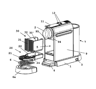
Figure 1 shows a liquid food or beverage machine according
to the invention. The machine has a liquid food or beverage
unit 2 in a housing 9. Unit 2 is arranged for receiving an
ingredient capsule or pod and feeding a liquid to the capsule
or pod. Unit 2 is mounted on a platform 1 and extends along a
lateral side 1' thereof. A beverage outlet 95 for dispensing
beverage from unit 2 extends through a front face 94 of housing
9.
Unit 2 includes a brewing module (not shown) that comprises
an opening and closure handle 11 and means for holding a
substance-containing capsule or pod, e.g., a coffee capsule,
and liquid food or beverage delivery means such as a liquid
food or beverage duct 95. The holding means typically comprises
a capsule holder and a brewing cage, a fluid injection system
for injecting water in the capsule and a closure device such as
a lever and a knee joint mechanism. Suitable extraction modules
are described in EP 1 859 713. Further possible features of
unit 2 are discussed in greater details in co-pending
application EP07123009.
Furthermore, housing 9 houses within a receptacle seat a
used capsule or pod receptacle 30 that has a front face 31 and
that is removably inserted under the brewing unit and outlet
95, in accordance with the invention. Receptacle 30 and its
seat in housing 9 will be discussed in greater details in
relation with Figs 2 to 8b.
Platform 1 has at least the minimal functions as to the
fluid and power management, which is supplying the liquid food
or beverage unit 2 with electrical power and with water from
water tank 7 attached to the base
CA 02707854 2015-02-25
- 10 -
platform externally to housing 9 and adjacent to the rear wall
of housing 9.
A master switch 3 is mounted on platform 1 for shutting on
and off the machine. Two user-buttons 12, typically for
selecting a small or large quantity of liquid food or beverage
to be prepared, are located above unit 2.
Upper face 34 of platform 1 has means in the form of a
STRIXTm connector (not shown) for connecting a milk frothing
device 8. Such disconnectable connectors for the beverage or
liquid food machine and frothing device 8 are for example
disclosed in greater detail in WO 03/075629, WO 2008/046837 and
in PCT/EP08/056349.
Upper face 34 is adjacent neighbouring front face 35 that
can be associated with a heating system, in particular
integrated in platform 1, and that may be arranged to support
one or more cups or mugs for pre-heating thereof prior to use.
As mentioned above, liquid food or beverage unit 2
generally extends upwards within housing 9 adjacent a first
lateral edge 1' of platform 1. Frothing device 8 is generally
located adjacent a second lateral edge of platform 1 opposite
the first edge 1", so that housing 9 and platform 1 generally
form in cross-section an L-shape that supports frothing device
8.
The liquid food or beverage machine also includes a support
device 6 for supporting mugs that is located under beverage
outlet 95 and that is in the shape of a perforated plate for
evacuating liquid. A collector 6a in the form of a shallow
reservoir is located underneath support device 6 for collecting
the evacuated liquid. Collector 6a does not require a high
capacity for collecting liquid. Most of the time, collector 6a
will only have to collect drips and spills.
CA 02707854 2010-06-03
WO 2009/074559
PCT/EP2008/067083
- 11 -
Support device 6 and collector 6a are separable en
bloc from platform 1, for instance for emptying collector
6a and/or for cleaning.
Furthermore, the liquid food or beverage machine
has, above support device 6, a second support plate 21
for supporting recipients, such as cups, of smaller size
underneath the outlet 95. Like main support device 6,
second support plate 21 comprises a perforated plate for
the evacuation of liquid, in particular to collector 6a,
optionally via support device 6. Second support plate 21
is movable into a generally horizontal operative position
between the outlet 95 and support device 6, as
illustrated, and is movable into a generally upright or
vertical rest position away therefrom so that a larger
recipient is placeable on support device 6 under outlet
95. Second support plate 21 is in particular rotatable
and/or slidable from its operative position into its rest
position. Further details of possible features of such
second support device are for example disclosed in EP 1
867 260.
Figure 2, in which the same numeric references
generally designate the same elements, shows another
embodiment of the invention.
The preparation machine shown in Fig. 2 has the same
features as the machine of Fig. 1 except for the absence
of the lateral platform extension supporting a milk
frothing device.
The preparation machine of Fig. 2 has a seat 5 for
receiving a receptacle 30 having a cavity 30' that forms
a storage space for collecting used capsules or pods.
Receptacle 30 may be assembled to a cup support
device 20 which includes cup support member 21 that is
pivotally mounted onto a reservoir 22 supporting
receptacle 30. Support member 21 is assembled to or
integral with a stop member 24 that is rotatable with
support member against a front face of reservoir 24 to
CA 02707854 2010-06-03
WO 2009/074559
PCT/EP2008/067083
- 12 -
stop the downward rotation of support member 21 and
secure member 21 in a horizontal position.
Receptacle 30 may have bottom part with a drain-hole
so that reservoir 22 can collect liquid drained from this
bottom part into reservoir 22 via the drain-hole. Cup
support device 20 and receptacle 30 resting thereon may
be inserted and removed en bloc from seat 5. Further
details of receptacle 30 and seat 5 are discussed in
relation with Figures 3a to 5b.
Also shown in Fig. 2, collector 6a supporting
support device 6 may be removably assembled via a
mechanical connector 4 to platform 1.
Figs 3a to 5a and 3b to 5b show in perspective view
and cross-sectional view, respectively, different
positions of receptacle 30 relative to seat 5: an
inserted position (Figs 3a and 3b); an intermediate
position (Figs 4a and 4b) at insertion or removal; and a
removed position (Figs 5a and 5b).
As can be seen in Figures 3a to 5b, the capsule or
pod collection arrangement of a machine according to this
embodiment of the invention includes three units, namely:
a capsule or pod receptacle 30; a cup support device 20
on which receptacle 30 is mounted; and a seat 5 for
housing receptacle 30 on cup support device 20.
Seat 5 is located within housing 9 underneath the
brewing unit (with handle 11) of liquid food or beverage
unit 2. Seat 5 has a bottom 53, a rear face 51, facing
side faces 51' and a front opening 5' (see Fig. 5a) for
allowing the insertion and the removal of receptacle 30
and reservoir 22.
Cup support device 20 comprises a perforated support
plate 21 that is hingedly assembled to liquid collection
reservoir 22 via axis 23. Collection reservoir 22 has a
rim that supports and holds capsule or pod receptacle 30,
so that reservoir 22 and receptacle 30 can be inserted
and removed from seat 5 en bloc.
CA 02707854 2010-06-03
WO 2009/074559
PCT/EP2008/067083
- 13 -
Receptacle 30 has a generally funnel-shaped bottom
35 with a through-hole 35' for evacuating liquid, in
particular from capsules or pods upon use or from a
cleaning or rinsing process of the preparation machine,
to reservoir 22 located underneath. Cavity 30' of
receptacle 30 is generally delimited by bottom 35, front
wall 31, facing sidewalls 32 and rear wall 33.
Receptacle 30 is so dimensioned that front wall 31
comes generally flush with front face 94 of housing 9
when receptacle 30 is in its operative position inserted
in seat 5. Front wall 31 can be transparent or
translucent to permit visual examination by a user of the
level of fill of receptacle 30 with capsules or pods.
Moreover, as shown in greater details in Fig. 6,
front wall 31 may have one or more through-openings 317
for the evacuation of steam from cavity 30' of receptacle
30, in particular a series of side-by-side elongated
through-openings, such as through-openings 317 extending
over substantially an entire height of front wall 31. In
one embodiment, wall 31 may include two adjacent parallel
lines 312,314 of generally vertically extending parallel
and spaced apart side-by-side members 311,313. These two
lines 312,314 of parallel upright members 311,313 can be
offset so that the parallel members 311,313 of the two
lines 312,314 are in a staggered arrangement, in a zig-
zag order, or in positions alternating on either side of
a median line 316 extending between the two lines
312,314. The two lines 312,314 of parallel upright
members 311,313 may extend between end portions 315 of
sidewalls 32 of receptacle 30.
In this configuration, the spaced apart upright
parallel members 311,313 may delimit therebetween
through-openings 317. In such an arrangement, through-
openings 317 have a flow-through orientation that is
parallel to the general direction 316 of front wall 31.
Hence, steam or fluid will not be able to project in
direct line from cavity 30' outside but will be diverted
the staggered arrangement 311,313.
CA 02707854 2010-06-03
WO 2009/074559
PCT/EP2008/067083
- 14 -
In accordance with the invention, the liquid food or
beverage preparation machine further comprises a means
for reducing the storage space of receptacle 30 at
insertion into seat 5 and for increasing the storage
space of receptacle 30 at removal from the seat 5.
In the embodiment shown in Figs 3a to 5b, such means
are provided, on the one hand, in the form of a through-
opening 34 delimited by rear wall 33 or receptacle 30
and, on the other hand, by a body 52 protruding out from
rear wall 51 or seat 5. Through-opening 34 and body 52
cooperate so that: when receptacle 30 is inserted in seat
5, body 52 extends via through-opening 34 into cavity 30'
of receptacle 30 whereby the storage space of cavity 30'
is reduced by the corresponding intruding volume of body
52, as illustrated in Figs 3a and 3b; when receptacle 30
is removed from seat 5, the volume previously occupied by
body 52 in cavity 30' is freed, whereby the storage space
of cavity 30' is increased in the absence of body 52 in
cavity 30', as illustrated in Figs 5a and 5b. During
removal or insertion of receptacle 30, body 52 retracts
from or penetrates into cavity 30' via through-opening 34
of rear wall 33, as shown in Figs 4a and 4b.
Hence, when cavity 30' is filled or even overfilled
with capsules or pods, a user may still remove receptacle
30 from seat 5 without risk of jamming receptacle 30, as
the removal operation increases the available storage
space of receptacle 30. As explained above, during
removal, body 52 withdraws from cavity 30' leaving
additional space therein. Conversely, when receptacle 30
is put back into place in seat 5 upon emptying, body 52
may freely enter empty cavity 30' to reduce its storage
capacity for the capsule or pod filling process.
Figs 9a and 9b, in which the same numeric references
generally designate the same elements, show two schematic
views from above of a variation of the receptacle and
seat shown in Figs 3a to 5b. Fig. 9a illustrates
receptacle 30 in its operative position for collecting
capsules or pods. Fig. 9b illustrates receptacle 30 in an
CA 02707854 2010-06-03
WO 2009/074559
PCT/EP2008/067083
- 15 -
intermediate position at removal (or insertion) into seat
of the preparation machine.
Instead of having a body of a seat that enters via a
through-opening in a middle part of the rear wall of the
5 receptacle like in Figs 3a to 5b, in Figs 9a and 9b seat
5 has a pair of spaced apart bodies 52',52" that are
located at opposite end corners of seat 5 and that are
arranged to enter laterally into cavity 30' via cut-outs
or through-openings 34',34" formed at rear corners
between sidewalls 32 and rear wall 33.
Likewise, through-opening 34',34" and bodies
52',52" cooperate so that: when receptacle 30 is
inserted in seat 5, bodies 52',52" extend laterally via
corresponding through-openings 34',34" into cavity 30'
of receptacle 30 whereby the storage space of cavity 30'
is reduced by the corresponding intruding volumes of
bodies 52',52", as illustrated in Fig 9a; when
receptacle 30 is removed from seat 5, the volumes
previously occupied by bodies 52',52" in cavity 30' are
freed, whereby the storage space of cavity 30' is
increased in the absence of bodies 52',52" in cavity
30', as illustrated in Fig. 9b. During removal or
insertion of receptacle 30, bodies 52',52" retract from
or penetrate into cavity 30' via through-openings
34',34" of sidewalls 32 and rear wall.
Figs 7a and 7b, in which the same numeric references
generally designate the same elements, schematically
illustrate a further embodiment of receptacle 30 and seat
5 of a liquid food or beverage preparation machine
according to the invention. Fig 7a illustrates receptacle
30 in its operative position in seat 5. Figure 7b
illustrates receptacle 30 during insertion into or
removal from seat 5.
In this embodiment, the means for reducing the
storage space of receptacle 30 at insertion into seat 5
and for increasing the storage space of receptacle 30 at
removal from the seat 5 include a pair of facing shells
CA 02707854 2010-06-03
WO 2009/074559
PCT/EP2008/067083
- 16 -
36,37 delimiting cavity 30' of receptacle 30. Shells
36,37 are movable relatively to one another to increase
and decrease the storage space of cavity 30'. In
particular, shells 36,37 are in a telescopic arrangement.
Peripheral portions 36a of walls 32 and bottom 35 of
shell 36 may slide in an out from grooves 37' in
corresponding peripheral portions 37a of walls 38 and
bottom 39 of shell 37. To avoid unwanted full separation
of shells 36,37, groove 37' and/or peripheral portions
36a may incorporate an abutment or like arrangement (not
shown), as known in the art.
During use, used capsules or pods are evacuated from
a brewing unit to passage 55 of seat 5 into cavity 30' of
receptacle 30. In this operative configuration,
receptacle 30 has its shells 36,37 urged together for
reducing the storage space of cavity 30', as illustrated
in Fig. 7a.
When receptacle 30 needs to be removed from seat 5,
e.g. for emptying, front shell 36 may first be pulled
out, e.g. telescoped out, for instance by means of a
handle or grip (not shown), while leaving rear shell 37
in place in seat 5 with rear walls 33,51 of receptacle 30
and seat 5 remaining together, as illustrated in Fig. 7b.
Hence, the size of cavity 30' of receptacle 30 is
correspondingly increased and capsules or pods collected
therein have an increased storage space in receptacle 30.
It follows that capsules or pods that would have been
accumulated above the mouth of receptacle 30, in
particular up to and into passage 55, so as to overfill
receptacle 30 in its operating position, are
redistributed in the enlarged cavity 30' having a larger
storage space. Such an arrangement significantly reduces
the risk of clogging or jamming of capsule or pod
collection receptacles at removal. When capsules or pods
stored in enlarged cavity 30' have freed the way out,
receptacle 30 may be further pulled along the same
direction to remove receptacle 30 including rear shell 37
entirely from seat 5.
CA 02707854 2010-06-03
WO 2009/074559
PCT/EP2008/067083
- 17 -
As apparent from Figs 7a and 7b, pivotable support
plate 21 should be in its deployed operative horizontal
position when receptacle 30 is being removed from or
inserted into seat 5. Furthermore, reservoir 22 holding
receptacle 30 may follow rear shell 37 and have a
corresponding shape to allow relative movements in seat 5
of front shell 37 on reservoir 22.
In a variation, it is of course possible to arrange
the receptacle and the reservoir so that the reservoir
follows the receptacle's front shell. In a second
variation, it is also possible to arrange the receptacle
and the reservoir so that the reservoir follows the
receptacle's front shell at insertion of the receptacle
into the seat and so that the reservoir follows the
receptacle's rear shell at removal of the receptacle from
the seat, or vice versa.
Figs 8a and 8b, in which the same numeric references
generally designate the same elements, schematically
illustrate a further embodiment of receptacle 30 and seat
5 of a liquid food or beverage preparation machine
according to the invention. Figure 7a illustrates
receptacle 30 during insertion into or removal from seat
5. Fig 7b illustrates receptacle 30 in its operative
position in seat 5.
In this embodiment, the means for reducing the
storage space of receptacle 30 at insertion into seat 5
and for increasing the storage space of receptacle 30 at
removal from the seat 5 include an elevator like platform
56 and a counter-body 58 in seat 5.
Elevator-like platform 56 is movable up and down by
means of drive rod 57. Platform 56 is arranged to support
bottom 35 of receptacle 30 and move receptacle 30 up and
down between bottom 53 and top 54 of seat 5. Furthermore,
seat 5 has a counter-body 58 that is arranged to reduce
the storage space of cavity 30' when receptacle 30 is in
its operative position to collect pods or capsules.
CA 02707854 2010-06-03
WO 2009/074559
PCT/EP2008/067083
- 18 -
This operative position of receptacle 30 is
illustrated in Fig. 8b. In this position, receptacle 30
is lifted by platform 56 against top 54 so that counter-
body 58 enters into receptacle 30 via its mouth for
reducing the storage space of cavity 30'. Capsules or
pods may be evacuated from the brewing unit into cavity
30' via passage 55 in counter-body 58.
When receptacle 30 is full or overfilled with
capsules or pods, in particular accumulated up into
passage 55, platform 56 with receptacle 30 may be lowered
as illustrated in Fig. 8a. In this lower position, the
top surface of platform 56 which contacts bottom 35 of
receptacle 30, comes generally flush with the top surface
of support plate 21 when in its deployed horizontal
operative position. Hence top surfaces of platform 56 and
of support plate 21 provide one substantially continuous
guide surface for moving receptacle 30 in and out from
seat 5. Moreover, the upper space or cavity 30'
previously occupied by counter-body 58, is freed and the
capsules or pods in excess may occupy this newly freed
space so as to reduce or eliminate the risk or clogging
or jamming receptacle 30 when pulled out of seat 5 via
opening 5'.
Unlike the previous embodiments, the receptacle and
seat schematically shown in Figs 8a and 8b are not
associated with a separated reservoir for collecting
liquid and the receptacle is not provide with a drain-
hole for evacuating such liquid to the reservoir. In this
embodiment, such liquid is directly collected and
accumulated on the bottom of the receptacle. Furthermore,
the pivotable support plate 21 is directly pivotally
mounted via axis 23 on seat 5 (or on the housing of the
preparation machine). Support plate 21 is connected to a
stop member 24 that is pivotable with support plate 21
against seat 21 (or against the housing of the
preparation machine) to hold and secure support plate 21
in a substantially horizontal operative position. Support
CA 02707854 2010-06-03
WO 2009/074559
PCT/EP2008/067083
- 19 -
plate 21 may also be pivoted upwards in an upright rest
position to cover opening 5'.
In a variation, it is also possible to move the
counter-body up and down in the cavity of the receptacle
so as to increase and decrease its storage space, instead
or moving the entire receptacle up and down by means of
the platform. In a further variation, it is also possible
to provide a reservoir for supporting the receptacle like
in the previous embodiments. In such a case, the
reservoir and the receptacle resting thereon may be
lifted or lowered together by the elevator-like platform.
Alternatively, the counter-body may be lowered and raised
in the receptacle.
In either case, whether the counter-body is lowered
into the receptacle or whether the receptacle is lifted
so that the counter-body enters the receptacle's mouthõ
the receptacle is safely secured in its operative
position within the seat and does not risk to come out or
fall out inadvertently.
A further elevator-type variation is shown in Figs
10a and 10b, in which the same numeric references
generally designate the same elements, where no counter-
body is arranged to enter into the cavity 30' of
receptacle 30. In this embodiment, the jamming inhibiting
means do not affect the storage space of receptacle 30.
If Figs 10a and 10b, elevator-like platform 56 is
movable up and down by means of drive rod 57. Platform 56
is arranged to support bottom 35 of receptacle 30 and
move receptacle 30 up and down between bottom 53 and top
54 of seat 5. Platform 56 is arranged to hold receptacle
30 in its operative position against top 54 (Fig. 10b)
and lower receptacle 30 for removal (Fig. 10a).
In the operating position, receptacle 30 capsules or
pods may be evacuated from the brewing unit into cavity
30' via passage 55.
When receptacle 30 is full or overfilled with
capsules or pods, in particular accumulated up into
CA 02707854 2010-06-03
WO 2009/074559
PCT/EP2008/067083
- 20 -
passage 55, platform 56 with receptacle 30 may be lowered
as illustrated in Fig. 10a. In this lower position,
remaining used capsules or pods may come down from
passage 55 to unclog receptacle 30, whereby receptacle 30
may be pulled out from seat 5 without having capsules or
pods interfering with an upper part of opening 5' of the
machine's housing.
Yet another elevator-type variation is schematically
illustrated in Figs 11a and 11b, in which the same
numeric references generally designate the same elements.
In this embodiment, bottom 35 of receptacle 30 is
movable up and down within a bottom part of receptacle 30
to reduce and increase, respectively the storage space of
cavity 30'. As illustrated, bottom 35 may be raised and
lowered by elevator platform 56 between abutments 33' and
bottom flanges 33" protruding from rear wall 33 and
front wall 31 of receptacle 30.
In a variation, it is also possible to replace the
elevator-type raising and lowering mechanism by a cam and
follower arrangement or another movement conversion
system from a horizontal insertion movement of the
receptacle into a vertical elevation movement of the
bottom of the receptacle, and from a horizontal removal
movement of the receptacle into a vertical lowering
movement of the bottom of the receptacle.
For instance, the movable bottom of the receptacle
may include horizontally extending cam followers that
protrude beyond the receptacle's sidewalls in a manner to
allow vertical movements of the cam followers. Moreover,
the sidewalls of the seat have corresponding cams in
which or against which the cam followers engage when the
receptacle is moved horizontally into the seat, the cams
being arranged so as to guide the cam followers upwards
as the receptacle is introduced into the seat and
downwards when the receptacle is removed from the seat.