Note: Descriptions are shown in the official language in which they were submitted.
CA 02708158 2010-06-04
WO 2009/074225 PCT/EP2008/010018
"Vibrating prilling bucket for granulation of a fluid
substance"
DESCRIPTION
Field of application
The present invention relates to a prilling bucket for the
granulation of a fluid substance.
The term prilling bucket is used with reference to a bucket
with a perforated side wall, to be mounted inside a
prilling tower, fed with said liquid substance and rotated
at a suitable speed, so that a flow of droplets of said
fluid substance is ejected through the perforated side
wall.
Prior Art
It is known art to convert a given fluid substance into
solid granules by means of a prilling tower wherein small
droplets of the fluid substance flow downward and in
countercurrent to a cooling medium, e.g. air. The small
droplets are solidified under the action of the cooling
medium and spherical or quasi-spherical granules are
obtained. Prilling towers are used for example at the end
stage of an urea plant, where liquid urea, with high degree
of purity, is solidified into granules which constitute the
final product.
A known way of producing said flow of small droplets is to
feed the liquid substance to a rotating, perforated
container located on top of the prilling tower, also known
as prilling bucket.
CONFIRMATION COPY
CA 02708158 2010-06-04
WO 2009/074225 PCT/EP2008/010018
2 -
More in detail, a known prilling bucket substantially
comprises a body connected to a rotating shaft, and having
a perforated side wall. The fluid substance is fed to the
bucket by a suitable feeding duct, for example coaxial to
the rotating shaft, and small droplets are produced and
ejected, by centrifugal force, through the perforated side
wall.
It is also known to vibrate the prilling bucket, normally
according to the same axis of rotation, in order to break
the liquid jets exiting the perforated side wall and
improve monodispersion (that is uniformity in size and
shape) of the droplets. A vibrating prilling bucket,
according to known art, is equipped with a suitable
vibrating unit, for example a pneumatic turbine vibrator. A
rotating and vibrating prilling bucket is disclosed in WO
2004/101131.
It should be noted that good monodispersion of the droplets
is difficult to obtain, and for some products (such as
urea) uniform size and shape of the solid granules
dramatically influences the value of the product. The
process involving formation and break-up of the liquid jets
is quite complex and is not easy to foresee the negative or
positive influence of any structural modification of the
bucket. Moreover, the bucket must be adapted for long-term
and reliable operation.
It should also be noted that a rotating and vibrating
prilling bucket is subjected to a relevant mechanical
stress, including alternate stress, and must be carefully
designed. This is true especially in large plants where the
bucket rotates at high speed (such as 200-300 rpm).
CA 02708158 2010-06-04
WO 2009/074225 PCT/EP2008/010018
- 3 -
So, the realization and optimization of a prilling bucket
is a challenging task, and a continuous need is felt to
improve the known technique.
Summary of the invention
The technical problem underlying the present invention is
to improve the known technique of prilling buckets, with an
aim to obtain a better monodispersion of the liquid
droplets and, hence, to obtain a final product of a higher
quality, with reliable long-term performance of the bucket
itself.
This problem is solved according to the invention by a
vibrating prilling bucket for granulation of a fluid
substance, said bucket comprising a body with a perforated
side wall substantially symmetrical with respect to an
axis, and further comprising a vibrating engine,
characterized in that said vibrating engine is arranged to
deliver, during operation, a vibration-driving force having
a substantially constant direction according to said axis
of the bucket.
Said substantially constant direction of the vibration-
driving force is also referred to as axis of vibration, and
is parallel or coincident with said axis of the bucket.
The term vibrating engine is used with general reference to
vibration imparting means, comprising for example vibrators
and relative feeding and/or connecting means.
According to embodiments of the invention, the prilling
bucket is adapted to rotation around an axis, and direction
of the vibration-driving force, namely the axis of
vibration, is parallel to, or coincident with, the axis of
rotation. Normally the prilling. bucket is installed on top
CA 02708158 2010-06-04
WO 2009/074225 PCT/EP2008/010018
4 -
of a vertical prilling tower, so that the axis of rotation
and the axis of vibration are both vertical.
According to one aspect of the invention, said vibrating
engine is arranged to deliver a plurality of rotating
forces, said forces being mutually balanced according to
directions perpendicular to the axis of vibration, so that
the resulting vibration-driving force transmitted to the
bucket has a variable module but is constantly directed
according to said axis of the bucket.
The term "rotating force" means a force which can be
schematized with a vector rotating around a given fixed
axis, as a function of time.
According to a further aspect of the invention, the
vibrating engine is arranged to deliver counter-rotating
forces lying on planes parallel to said axis of the bucket,
i.e. to axis of vibration. For example, two counter-
rotating forces are generated by the vibrating engine and
each of said two forces is lying on a plane parallel to the
axis of vibration, so that in each instant of time, their
components according to said axis of vibration are added,
while other components are mutually balanced.
In a preferred embodiment, the vibrating engine comprises
counter-rotating rotors to deliver said counter-rotating
forces. More preferably, the engine comprises a pair of
vibrators with respective identical unbalanced rotors or
turbines, disposed to be counter-rotating at the same
speed; the term unbalanced turbine is used to mean a
turbine with an eccentric distribution of mass, so that
rotation of the turbine produces a force rotating on a
plane perpendicular to axis of rotation.
CA 02708158 2010-06-04
WO 2009/074225 PCTIEP2008/010018
- 5 -
More in detail, and according to preferred embodiments, a
first turbine is arranged to rotate around a first axis and
a second turbine, identical to the first, is arranged to
counter-rotate in phase with the first turbine, at the same
speed and around a second axis parallel to said axis of
rotation of the first turbine, each of said first axis and
second axis of rotation of the turbines lying on a plane
perpendicular to said axis of vibration. Preferably said
first axis of rotation and second axis of rotation lie on
the same plane perpendicular to the axis of vibration.
Due to said arrangement, the turbines deliver a first
rotating force and a second rotating force having the same
module and lying on planes parallel to the axis of
vibration; components of said rotating forces perpendicular
to the axis of vibration are always equal and opposite, and
thus balance each other. The resulting force is then
directed according to said axis of vibration. This will be
more evident with the help of non-limiting examples given
in the detailed description.
According to another aspect of the invention, said turbines
are mechanically coupled to maintain phased counter-
rotation in a reliable manner. In a preferred embodiment, a
first gear wheel is fixed to the shaft of the first
turbine, and a second gear wheel is fixed to the shaft of
the second turbine, the first gear wheel being engaged with
said first gear wheel. Phased rotation helps to keep a
constant balance of forces perpendicular to the axis of
vibration.
In a preferred embodiment, the vibrators are pneumatically
operated, that is powered by compressed air. Pneumatic
vibrators are preferred because of their ability to operate
CA 02708158 2010-06-04
= WO 2009/074225 PCT/EP2008/010018
- 6 -
under the high working temperature of the bucket (around
150 C for processing urea).
According to embodiments of the invention, the vibration-
driving force can be transmitted to the whole body of the
prilling bucket or to a part thereof, namely the perforated
side wall only. To this purpose, an embodiment of the
invention provides said vibrating engine coupled to the
perforated side wall of the bucket, and a flexible
connection between the side wall and other parts of the
bucket, namely top and bottom flanges, said flexible
connection acting as a mechanical filter for the vibration-
driving force.
An object of the invention is also a granulation apparatus
with a prilling tower equipped with at least one prilling
bucket as above. Two or more prilling buckets, running in
parallel, can be used in large or very large capacity
plants.
The inventions has a number of advantages. It has been
found that monodispersion of droplets is improved by the
"pure" vertical vibration provided by the invention,
compared to a known prilling bucket wherein the vibrating
engine is unbalanced, and vibrations are. transmitted also
in directions other than the main axis of vibration, or
discharged to the supports of the bucket and/or the shaft.
Furthermore, the invention results in a less severe
mechanical stress of the supports and bearings of prilling
bucket. Reduced stress improves the reliability and makes
easier the achievement of higher rotating speed and/or
higher frequency of vibration, as required especially in
large-capacity units.
CA 02708158 2010-06-04
M =
WO 2009/074225 PCT/EP2008/010018
7 -
Another advantage is that the balanced vibration can be
obtained with low-cost and commonly available vibrating
units, for example pneumatic turbine vibrators, requiring
no or minor modification for use in the prilling bucket
according to the invention.
Further features and the advantages of the invention will
become clearer from the following description of an
indicative and non-limiting example of embodiments thereof,
made with reference to the attached drawings.
Brief description of the figures
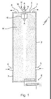
Fig. 1 shows a simplified scheme of a prilling tower
equipped with a prilling bucket according to the invention.
Fig. 2 is a schematic cross section of a prilling bucket
according to an embodiment of the invention.
Fig. 3 is a schematic cross section of a prilling bucket
according to another embodiment of the invention.
Fig. 4 is a cross section according to planes IV-IV as
indicated in Figs. 2 and 3.
Fig. 5 is a scheme of the forces produced by vibrating
devices of the prilling bucket of Fig. 2 or 3.
Detailed description of a preferred embodiment of the
invention
With reference to Fig. 1, a prilling tower 1 is shown,
having a cylindrical shell 2 with vertical axis A-A closed
by a base plate 3 and a top wall 4.
Ducts 5 and 6 are provided near base plate 3, for input of
a continuous rising flow of a cooling medium (for example
CA 02708158 2010-06-04
WO 2009/074225 PCT/EP2008/010018
8 -
air) through tower 1. Ducts 7 and 8 are provided at the top
wall 4 for discharging said cooling medium.
A fluid substance U to be granulated is fed to a prilling
bucket 15 installed at top of the tower 1. In operation,
the prilling bucket 15 is rotated around axis A-A and
vibrated according to direction of the same axis A-A,
producing a downward flow W of droplets of substance U,
which are cooled by the rising cooling air until they
solidify into spherical or substantially spherical
granules. Solid granules are discharged through a bottom
aperture E.
More in detail, the fluid substance U is fed through a
feeding duct 10 connected to an axial duct 9 crossing the
top wall 4. The droplets of said substance U are produced
by a perforated side wall of the prilling bucket 15.
The bucket 15 (Fig. 2) has a frusto-conical body comprising
top and bottom flanges (or bases) 15b, 15c and a perforated
side wall 15a substantially symmetrical around axis A-A.
Said flanges and perforated wall define a chamber 15d
adapted to contain a given amount of fluid substance U.
The bucket 15 is connected to a motorized driving shaft 14,
rotating around axis A-A and powered by a suitable motor
(not shown).
The bucket 15 is also equipped with a vibrating engine V,
adapted to provide a vibration of the bucket itself at a
suitable frequency and according to said axis A-A, which
can also be referred to as axis of vibration.
The vibrating engine V is arranged to deliver a variable
(pulsating) force which is constantly directed according to
A-A, with no or negligible component directed otherwise. In
CA 02708158 2010-06-04
WO 2009/074225 PCT/EP2008/010018
9 -
the preferred embodiment of the figures, this is
accomplished by two identical vibrators 51, 52 with in-
phase counter-rotating unbalanced turbines, which are
arranged so that they balance each other in directions
other than A-A.
The prilling bucket 15 is now described in greater detail
with reference to the embodiments shown. The duct 9 has a
first portion 9a above plate 15b and extending outside the
shell 2, connected to duct 10, and a second portion 9b
extending inside the chamber 15d. Top and bottom of duct 9
are closed by respective plates 11, 12. The portion 9b of
duct 9 is equipped with circumferential slits 13 suitable
for delivering the fluid substance U inside chamber 15d.
The motorized shaft 14 is coaxial to duct 9, passing
through openings lla, 12a of plates 11 and 12 respectively,
with possible interposition of gaskets (not represented). A
reduced-diameter portion 14b of shaft 14 is connected to a
base 17 of bottom flange 15c.
Connection between shaft 14 and bottom flange 15c is such
that rotation of shaft 14 puts into rotation the flange 15c
itself and hence wall 15a and top flange 15b. Preferably,
the connection between shaft 14 and bottom flange 15c
allows axial displacement between the.shaft and the flange.
This connection, being not part of the invention, is not
described in further detail. A connection according to WO
2004/101131, for example, can be used.
A carter 50 is fixed to said base 17 of bottom flange 15c,
housing the vibrators 51, 52. Said vibrators 51, 52 are
powered by a compressed air duct 27 coaxial to shaft 14.
Air is fed in parallel to vibrators 51 and 52 by further
ducts 28.
CA 02708158 2010-06-04
WO 2009/074225 PCT/EP2008/010018
-
Each of vibrators 51, 52 comprises a strongly unbalanced
turbine or rotor, producing a rotating force in planes
parallel to A-A; traces tl and t2 of said planes are shown
in Fig. 2 for the sake of clarity.
5 The vibrators 51, 52 are arranged so that the respective
turbines are counter-rotating; furthermore, the turbines
are mechanically connected to be maintained in phase, so
that forces other than vertical are mutually balanced and
the resulting force is substantially directed according to
10 the vertical direction, i.e. according to axis A-A.
A further embodiment is shown in Fig. 3. Elastic rings 42,
44 provide a flexible connection between the perforated
side wall 15a and flanges 15b and 15c, while the side wall
15a is firmly connected, through a further flange 24, to
the vibrating units 51, 52. The flexible connection of said
rings 42, 44 substantially acts as a mechanical filter,
i.e. the vibration-driving force imparted to the side wall
15a is substantially not transmitted to the plates 15b,
15c. Rings 42, 44 are substantially rigid in the torsional
direction, in order to transmit driving torque from bottom
flange 15c to flange 24 and side wall 15a. Blades 20 are
provided to connect flanges 15b, 15c.
The upper and lower rims of the side wall 15a have fixing
portions 40, 43 with increased thickness to provide
25, suitable room for fixing means. As an example, a first set
of screws connects a region 24b of flange 24 to said fixing
portion 40 with interposition of elastic ring 42, and a
second set of screws is fixing the elastic ring 42 to the
flange 15c.
CA 02708158 2010-06-04
WO 2009/074225 PCT/EP2008/010018
- 11 -
The flange 24 is elastically supported, in the axial
direction A-A, to the end of the shaft 14, by a first
spring 32 and a second spring 33. Other elastic means, e.g.
elastomers, may be used; damping means can also be
provided, if necessary. Fig. 3 also shows a key 21 coupling
shaft 14 to flange 15c of the prilling bucket 15.
The carter 50, in this embodiment, is fixed to a portion
24a of flange 24. Vibrating engine V can be realized as
above, with vibrators 51 and 52.
In further embodiments of the invention, said flexible
connection can be made with one or more expansion joint(s),
e.g. two expansion joints mounted in the same positions as
elastic rings 42, 44.
Details and operation of vibrators 51, 52 is now described
with reference to Figs. 4 and 5.
The vibrators 51, 52 comprise respectively a first turbine
53 rotating around axis x-x and a second turbine 54
rotating around axis y-y. Axes x-x and y-y are parallel
each other and lie on a plane perpendicular to A-A.
Turbines 53 and 54 deliver forces rotating on a plane
perpendicular to respective axes x-x and y-y, that is said
rotating forces lie on planes parallel to A-A and having
traces tl and t2 as shown in Fig. 2.
Turbines 53 and 54 are kept in phase by a first gearwheel
55 coupled to turbine 53 and a second gearwheel 56 coupled
to turbine 54 and engaged with the first gearwheel 55, with
transmission ratio 1:1. According to one feature of the
invention, known vibrators are modified to mount the
gearwheels, e.g. keyed to the same shaft of the turbines.
CA 02708158 2010-06-04
WO 2009/074225 PCTIEP2008/010018
- 12 -
Vibrators 51, 52 are not described in greater detail as
they are commercially available items.
Referring to fig. 5, turbine 53 rotates with speed cal and
turbine 54 counter-rotates with speed cat, having the same
value of speed cal but opposite sense. Turbines 53 and 54,
due to their arrangement, deliver forces Fl and F2 having
equal module F, opposite horizontal components F1H, F2H and
concurrent vertical components F1V, F2V.
Forces Fl and F2 are rotating forces, that is vectors of
forces Fl and F2 rotates around the same axis of turbines
53 and 54, with speed cal and cat respectively. Due to phase
rotation, vectors of forces F1 and F2, in each instant of
time, maintain opposite horizontal components and
concurrent vertical components.
Hence, in each instant of time horizontal forces balance
each other, while vertical components are added. As a
result, a vertical force R pulsating between +2F and -2F is
transmitted to the bucket 15. It can be appreciated that
force R has a substantially constant direction, according
to axis A-A, which in the given example is the vertical
direction.
Due to gearwheels 55 and 56, phased rotation is maintained
and horizontal components F1H, F2H have always same value
and opposite direction, so that they balance each other and
direction of R is kept substantially constant and directed
according to A-A.
It should also be noted that more than two (e. g. four)
vibrators may be used in a single bucket 15.
CA 02708158 2010-06-04
WO 2009/074225 PCT/EP2008/010018
- 13 -
The invention operates as follows. The liquid substance U,
for example purified urea produced in a suitable plant, is
fed through ducts 10 and 9 to the prilling bucket 15, which
produces a downward flow W of droplets (Fig. 1) into the
tower 1. The force R delivered by vibrators 51 and 52 is
transmitted, as a vibration-driving force, to the bucket
15. More in detail, the force R causes alternate, vibrating
motion of perforated side wall 15a and of the liquid jets
exiting the perforated side wall itself. Said vibration is
a disturbance which helps the breaking up of the liquid
jets into a stream of uniform droplets.
The embodiment of Fig. 3 has the advantage of a further
improved monodispersion and a reduced vibrating mass, as
flanges 15b and 15c are not put into vibration together
with side wall 15a. Also the fluid mass between flanges 15b
and 15c is not put into vibration.
The balanced action of vibrators 51 and 52 (Figs. 4-5)
reduces mechanical stress and has been found to improve the
formation of spherical, monodispersed droplets.