Note: Descriptions are shown in the official language in which they were submitted.
CA 02708217 2013-07-15
TOILET FLAPPER FLUSH VALVE ASSEMBLY
BACKGROUND OF THE INVENTION
1. Field of the Invention
The present invention relates generally to toilet flush valves.
2. Description of Prior Art and Related Information
Conventional toilet flapper valves are susceptible to a variety of shortfalls.
Since the flapper valves are typically manufactured according to exact
specifications, a particular flapper valve may only be used with a
specifically sized
overflow tube. Flapper valves according to the prior art are also typically
installed
next to the rear vertical wall of toilet tanks. Rotation of the conventional
flapper
valves in response to flushes causes the mounting ears to rotate. Depending
upon
the distance between the rotating mounting ears and the toilet tank wall, a
conventional flapper valve can get stuck in the open position as the mounting
ears
abut the vertical wall. This leads to excessive water loss as well as the need
to
manually close the flapper valve.
SUMMARY OF THE INVENTION
The present invention provides structures and methods which overcome the
deficiencies in the prior art.
In one aspect, there is provided a flush valve assembly, comprising: a flapper
portion coupled to a pivot member and rotatable with respect to a valve seat;
and a
first mounting arm and second mounting arm coupled to the flapper portion and
the
pivot member, the first mounting arm being adjustable with respect to the
second
mounting arm so as to vary a distance therebetween, wherein: the first
mounting
arm comprises a first tab; the second mounting arm comprises a second tab; and
the flapper portion comprises a first opening for receiving the first tab and
a second
opening for receiving the second tab.
1
, CA 02708217 2013-10-28
,
The flapper portion comprises a first detent for locating the first mounting
in a
first fixed position, and a second detent for locating the second mounting arm
in a
second fixed position. The flapper portion has a top planar wall that defines
a plane.
The first mounting arm is movable with respect to the second mounting arm in a
direction parallel to the plane. The pivot member comprises a mounting ear
having
an extension.
In another aspect, there is provided a flush valve assembly, comprising: a
pivot member coupled to an overflow tube; a flapper portion coupled to the
pivot
member and rotatable with respect to a valve seat; at least one extension
member
coupled to the pivot member to space the flapper portion away from a vertical
sidewall of a toilet tank; and a first mounting arm and second mounting arm
coupled
to the flapper portion and the pivot member, the first mounting arm being
adjustable
with respect to the second mounting arm so as to vary a distance therebetween,
wherein: the first mounting arm comprises a first tab; the second mounting arm
comprises a second tab; and the flapper portion comprises a first opening for
receiving the first tab and a second opening for receiving the second tab.
The pivot member comprises a first axle and a second axle. A first extension
member comprises a first mounting ear coupled to the first axle, the first
mounting
ear having a first extension. A second mounting ear is coupled to the second
axle,
the second mounting ear having a second extension.
In another aspect, there is provided a method for installing a flush valve,
comprising: providing a flapper valve with a first mounting arm and a second
mounting arm wherein: the first mounting arm comprises a first tab; the second
mounting arm comprises a second tab; and the flapper valve comprises a first
opening for receiving the first tab and a second opening for receiving the
second tab;
adjusting the first mounting arm to vary a distance between the first mounting
arm
and the second mounting arm; and coupling the first mounting arm and the
second
mounting arm to a pivot.
The method further comprises preventing the mounting arms from contacting
a sidewall of a toilet tank when rotating. The step of preventing the mounting
arms
2
CA 02708217 2013-07-15
from contacting the sidewall of the toilet tank when rotating comprises
providing an
extension on a mounting ear of the pivot.
The method also includes retrofitting an existing flush valve assembly and
thus further comprises removing an existing flapper valve from an existing
overflow
tube. The step of coupling the first mounting arm and the second mounting arm
to
the pivot comprises coupling the first mounting arm and the second mounting
arm to
the pivot connected to the existing overflow tube.
In summary, a flapper flush valve assembly includes a pair of laterally
movable mounting arms which may be adjusted to vary a width therebetween to
accommodate overflow tubes of different sizes. The flapper valve assembly is
coupled to pivot members connected to an overflow tube. Mounting ears on the
pivot
members may include projections to provide spacing between the rotating
mounting
arms and adjacent sidewall of a toilet tank, thereby preventing jams.
The invention, now having been briefly summarized, may be better
appreciated by the following detailed description.
3
CA 02708217 2010-06-07
WO 2009/073143
PCT/US2008/013189
BRIEF DESCRIPTION OF THE DRAWINGS
FIG. 1 is an exploded view of a preferred embodiment of a flapper valve
assembly;
FIG. 2 is a top view of the preferred flush valve body;
FIG. 3 is a perspective view of a preferred flush valve body;
FIG. 4 is a top exploded view of a preferred embodiment of a flapper;
FIG. 5 is a top plan view of the preferred embodiment of the flapper;
FIG. 6 is a bottom perspective view of the flapper valve assembly;
FIG. 7 is a top plan view of an alternative flapper valve body; and
FIG. 8 is a diagram of a preferred method for installing a flush valve.
4
CA 02708217 2010-06-07
WO 2009/073143
PCT/US2008/013189
DETAILED DESCRIPTION OF THE PREFERRED EMBODIMENTS
The invention and its various embodiments can now be better understood by
turning to the following detailed description wherein illustrated embodiments
are
described. It is to be expressly understood that the illustrated embodiments
are set
forth as examples and not by way of limitations on the invention as ultimately
defined
in the claims.
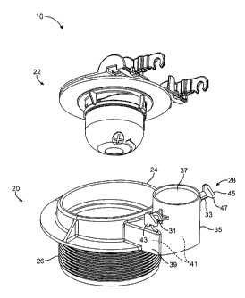
In FIG. 1, a preferred embodiment of a flush valve assembly is illustrated and
designated generally by the reference numeral 10. The assembly 10 comprises a
flush valve body 20 and a flapper apparatus, or simply flapper, 22. The valve
body
20 comprises a valve seat 24 and an externally threaded cylinder 26 extending
downwardly therefrom. A pivot 28 comprises first and second axles 31, 33
extending
horizontally from a conduit 35 with an open top 37 configured to be coupled to
an
overflow tube. The conduit 35 and a horizontal tube 39 collectively define a
passageway 41 that is in fluid communication with the cylinder 26. Each axle
31, 33
includes a corresponding mounting ear 43, 45 disposed at an outer end.
In Figures 1-3, each mounting ear 43, 45 includes a rearwardly extending
protrusion, or extension, 47 configured to project rearwardly and abut an
adjacent
toilet tank sidewall so as to provide space between the sidewall and the axles
31, 33.
The preferred flush valve body 20 may be used with conventional flappers or
with the
preferred flapper 22 according to a preferred embodiment of the invention. The
extended mounting ears 43, 45 prevent the mounting arms of flappers from
getting
jammed against an adjacent sidewall of the toilet tank, particularly when a
flush is
activated and the flapper is in the open position. When jammed, excess water
continues to flow into the toilet tank. Thus, the water conservation benefits
of
preventing flapper jams will be appreciated as the preferred flush valve body
20
5
CA 02708217 2010-06-07
WO 2009/073143
PCT/US2008/013189
prevents a significant amount of water from being wasted through an otherwise
jammed flapper. The preferred flush valve body 20 also prevents the
inconvenience
of a user having to open a toilet lid and manually closing the flapper.
In Figure 4, the preferred flapper 22 comprises a float 51 generally disposed
beneath a valve seal 53. The valve seal 53 is preferably formed as a disk or
ring
and composed of an elastomeric material. The valve seal 53 is coupled to a
bottom
side of a flapper frame 55. A hook 57 disposed on top the frame 55 is
configured to
be coupled to a chain or other fastener.
The frame 55 preferably comprises an outer portion 59 which defines a plane
A. The flapper 22 comprises a first mounting arm 61 and a second mounting arm
63
which are preferably, but not necessarily, identical in structure. In the
preferred
embodiment, the mounting arms 61:63 are removably coupled to the frame 55.
Each mounting arm 61, 63 is received in a corresponding groove 65 formed in
the
frame 55. Each mounting arm 61, 63 comprises a hook 67 at a pivot end 68 for
engaging the pivot 28 and a tab 70 at an opposite frame end 71 for engaging
the
groove 65 in the frame 55.
It is to be expressly understood that the frame 55 may be formed with a
variety of different grooves or other connecting mechanisms to removably
secure the
mounting arms 61, 63. In the preferred embodiment, each groove 65 may be
defined by a raised surface 72 generally parallel to the plane A, an outer, or
lateral,
wall 74 perpendicular to the plane A, and one or more inner, or medial, walls
76
perpendicular to the plane A. Each set of lateral wall 74 and medial walls 76
defines
a range of lateral movement, or adjustability, for each mounting arm 61, 63.
Each
groove 65 is further defined by a floor 79 which may include detents to
releasably
position the mounting arms 61, 63 at predetermined fixed locations.
6
CA 02708217 2010-06-07
WO 2009/073143
PCT/US2008/013189
At or adjacent to the frame end 71, each mounting arm 61, 63 may include an
arm wall 81 that is perpendicular to the plane A, as shown in Figure 4, and a
clip 83,
as shown in Figure 5, for releasably engaging an indented underside 85 of the
frame
55. Each mounting arm 61, 63 may also include a hollow receptacle 87 located
at a
central section which serves to receive a counterbalance such as a bucket
float.
In Figure 6, it will be appreciate that a width W between the pair of
laterally
movable mounting arms 61,63 may be adjusted to accommodate overflow tubes of
different sizes. Accordingly, the preferred flapper 20 may be used not only in
installing a new toilet, but also in retrofitting an existing toilet. The
preferred flapper
20 may thus be used in conjunction with an existing overflow tube. Detents 88
may
be provided to facilitate fixed positions of the mounting arms when 61, 63.
Figure 7 is a top plan view of an alternative embodiment of a flush valve body
90. In Figure 7, a pair of rearwardly protruding ribs 92 may be coupled to or
formed
as part of the overflow tube 94 so as to provide sufficient space 96 between
the
rotating arms 97 and the adjacent tank sidewall 98. In
Figure 8 illustrates a preferred method 100 for installing a flush valve. The
method 100 comprises a step 110 of providing a flapper valve with a first
mounting
arm and a second mounting arm. Step 120 includes adjusting the first mounting
arm
to vary a distance between the first mounting arm and the second mounting arm.
Step 130 includes coupling the first mounting arm and the second mounting arm
to a
pivot. Step 140 includes preventing the mounting arms from contacting a
sidewall of
a toilet tank when rotating. Step 140 may further comprise providing an
extension on
a mounting ear of the pivot.
The method 100 also comprises retrofitting an existing toilet tank with an
existing overflow tube. In step 150, an old existing flapper valve is
disengaged from
7
CA 02708217 2010-06-07
WO 2009/073143
PCT/US2008/013189
the existing overflow tube and removed. Step 150 also includes coupling the
new
flapper valve with the adjustable mounting arm or arms onto the pivot
connected to
the existing overflow tube. Whereas flappers are typically sold with overflow
tubes
as a combined package or kit, it will be appreciated that the preferred method
100
provides a modular solution
Many alterations and modifications may be made by those having ordinary
skill in the art without departing from the spirit and scope of the invention.
Therefore,
it must be understood that the illustrated embodiments have been set forth
only for
the purposes of examples and that they should not be taken as limiting the
invention
as defined by the following claims. For example, notwithstanding the fact that
the
elements of a claim are set forth below in a certain combination, it must be
expressly
understood that the invention includes other combinations of fewer, more or
different
elements, which are disclosed in above even when not initially claimed in such
combinations.
The words used in this specification to describe the invention and its various
embodiments are to be understood not only in the sense of their commonly
defined
meanings, but to include by special definition in this specification the
generic
structure, material or acts of which they represent a single species.
The definitions of the words or elements of the following claims are,
therefore,
defined in this specification to not only include the combination of elements
which
are literally set forth. In this sense it is therefore contemplated that an
equivalent
substitution of two or more elements may be made for any one of the elements
in the
claims below or that a single element may be substituted for two or more
elements in
a claim. Although elements may be described above as acting in certain
8
CA 02708217 2010-06-07
WO 2009/073143
PCT/US2008/013189
combinations and even initially claimed as such, it is to be expressly
understood that
one or more elements from a claimed combination can in some cases be excised
from the combination and that the claimed combination may be directed to a
subcombination or variation of a subcombination.
Insubstantial changes from the claimed subject matter as viewed by a person
with ordinary skill in the art, now known or later devised, are expressly
contemplated
as being equivalently within the scope of the claims. Therefore, obvious
substitutions now or later known to one with ordinary skill in the art are
defined to be
within the scope of the defined elements.
The claims are thus to be understood to include what is specifically
illustrated
and described above, what is conceptionally equivalent, what can be obviously
substituted and also what incorporates the essential idea of the invention.
9