Language selection

Search

Patent 2708419 Summary

Third-party information liability

Some of the information on this Web page has been provided by external sources. The Government of Canada is not responsible for the accuracy, reliability or currency of the information supplied by external sources. Users wishing to rely upon this information should consult directly with the source of the information. Content provided by external sources is not subject to official languages, privacy and accessibility requirements.

Claims and Abstract availability

Any discrepancies in the text and image of the Claims and Abstract are due to differing posting times. Text of the Claims and Abstract are posted:

  • At the time the application is open to public inspection;
  • At the time of issue of the patent (grant).
(12) Patent: (11) CA 2708419
(54) English Title: CRACK-PROOF SCREW
(54) French Title: VIS ANTI-FISSURES
Status: Deemed expired
Bibliographic Data
(51) International Patent Classification (IPC):
  • F16B 25/10 (2006.01)
  • F16B 33/02 (2006.01)
  • F16B 35/04 (2006.01)
  • F16B 39/282 (2006.01)
(72) Inventors :
  • LIN, TENG-HUNG (Taiwan, Province of China)
(73) Owners :
  • FONG PREAN INDUSTRIAL CO., LTD. (Taiwan, Province of China)
(71) Applicants :
  • FONG PREAN INDUSTRIAL CO., LTD. (Taiwan, Province of China)
(74) Agent: GELSING, SANDER R.
(74) Associate agent:
(45) Issued: 2017-05-09
(22) Filed Date: 2010-06-21
(41) Open to Public Inspection: 2011-12-21
Examination requested: 2015-04-08
Availability of licence: N/A
(25) Language of filing: English

Patent Cooperation Treaty (PCT): No

(30) Application Priority Data: None

Abstracts

English Abstract

A crack-proof screw comprises a head; a rod having a first end extending from the head and having a rod thread near the head and expanding threads far away from the head; each expanding thread encircled through an angle smaller than 360 degrees; the screwing direction of the expanding thread being identical to or different from that of the rod thread; a tapered tail extending from a second end of the head; the expanding threads on the rod being near the tapered tail; the tapered tail having two drilling threads; each drilling thread can be extended to or not extended to the tip end of the tapered tail.


French Abstract

Une vis anti-fissures comprend une tête; une tige comportant une première extrémité se prolongeant de la tête et comportant des filets de tige à proximité de la tête et éloignant les filets de la tête; chaque filet d'extension est encerclé dans un angle inférieur à 360 degrés; la direction de vissage du filet d'extension étant identique ou différente de celle du filet de la tige; une extrémité conique se prolongeant dune deuxième extrémité de la tête; les filets d'extension de la tige étant proche de l'extrémité conique; lextrémité conique comportant deux filets de forage; chaque filet de forage peut s'étendre ou ne pas s'étendre de l'extrémité de la pointe de lextrémité conique.

Claims

Note: Claims are shown in the official language in which they were submitted.

THE EMBODIMENTS OF THE INVENTION IN WHICH AN EXCLUSIVE
PROPERTY OR PRIVILEGE IS BEING CLAIMED ARE DEFINED AS FOLLOWS:
1. A crack-proof screw comprising:
a head,
a rod having a first end extending from the head and having a rod
thread near the head and expanding threads far away from the head;
each expanding thread encircled through an angle smaller than 360
degrees, the screwing direction of the expanding thread being identical to or
different from that of the rod thread; an angle A being defined as an angle
between
an upper side of each expanding thread and a line vertical to a surface of the
rod;
an angle B being defined as an angle between an lower side of each expanding
thread and a line vertical to a surface of the rod; the angle B being greater
than the
angle A and the summation of the angle B and angel A being equal to or greater

than 90 degrees,
a tapered tail extending from a second end of the rod, the expanding
threads on the rod being near the tapered tail; the tapered tail having two
drilling
threads; each drilling thread can be extended to or not extended to the tip
end of the
tapered tail
2. A crack-proof screw comprising
a head having a lateral surface which is formed with an axial annular
outer ring at an upper side thereof, an upper annular area of the annular
outer ring
6


being a flat ring portion and a lower annular area of the annular outer ring
being a
ratchet tooth area, a lower side of the lateral surface of the head being
formed with
ratchet teeth,
a rod having a first end extending from the head and the rod having a
rod thread near the head and expanding threads far away from the head,
each expanding thread encircled through an angle smaller than 360
degrees; the screwing direction of the expanding thread being identical to or
different from that of the rod thread; an angle A being defined as an angle
between
an upper side of each expanding thread and a line vertical to a surface of the
rod;
an angle B being defined as an angle between an lower side of each expanding
thread and a line vertical to a surface of the rod; the angle B being greater
than the
angle A and the summation of the angle B and angel A being equal to or greater

than 90 degrees; and
a tapered tail extending from a second end of the rod; the expanding
threads on the rod being near the tapered tail; the tapered tail having two
drilling
threads; each drilling thread can be extended to or not extended to the tip
end of the
tapered tail.

7

Description

Note: Descriptions are shown in the official language in which they were submitted.


CA 02708419 2010-06-21
"CRACK-PROOF SCREW"
FIELD OF THE INVENTION
The present invention relates to screws, and in particular to a crack-
proof screw which includes a rod thread, expanding threads and drilling
threads.
The screw of the present invention can drill an object quickly with less force
and
achieve the object of the crack-proof.
BACKGROUND OF THE INVENTION
Many design ways are used in designs of screws, such as single
section, double sections, single thread, double threads, single diameter,
double
diameters, single pitch angle, double pitch angles, etc. All these designs
present
different effects in use of screws, such as the effects of drilling speeds,
dregs
removing, and retaining.
In the design of the screws, the designs of screws are based on
the characters of the material and the object to be drilled. Generally, screws
are
made of different material, such as woods, plastics, metals, compound
materials,
etc. For a screw screwing into a wood, due to the property of the wood, it is
often
that the wood will crack. Thus it is necessary to have screws which have the
property of crack proof.

CA 02708419 2010-06-21
=
SUMMARY OF THE INVENTION
The object of the present invention is to provide a crack-proof screw
which includes a rod thread, expanding threads and drilling threads. The screw
of
the present invention can drill an object quickly with less force and achieve
the
object of the crack-proof.
To achieve above object, the present invention provides a crack-proof
screw comprising: a head having a lateral surface which is formed with an
axial
annular outer ring at an upper side thereof; an upper annular area of the
annular
outer ring being a flat ring portion and a lower annular area of the annular
outer ring
being a ratchet tooth area; a lower side of the lateral surface of the head
being
formed with ratchet teeth; a rod having a first end extending from the head
and
having a rod thread near the head and expanding threads far away from the
head;
each expanding thread encircled through an angle smaller than 360 degrees; the

screwing direction of the expanding thread being identical to or different
from that of
the rod thread; an angle A being defined an angle between an upper side of
each
expanding thread and a line vertical to a surface of the rod; an angle B being

defined an angle between an lower side of each expanding thread and a line
vertical to a surface of the rod; the angle B being greater than the angle A
and the
summation of the angle B and angel A being equal to or greater than 90
degrees;
and a tapered tail extending from a second end of the head; the expanding
threads
on the rod being near the tapered tail; the tapered tail having two drilling
threads;
each drilling thread can be extended to or not extended to the tip end of the
tapered
tail.
2

CA 02708419 2010-06-21
The various objects and advantages of the present invention will be
more readily understood from the following detailed description when read in
conjunction with the appended drawing.
BRIEF DESCRIPTION OF THE DRAWINGS
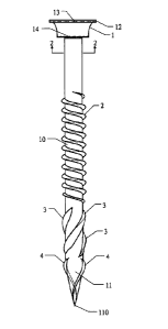
Fig. 1 shows the structure of the present invention.
Fig. 2 is a cross sectional view viewed from the line 2-2 of Fig. 1.
Fig. 3 is a schematic view showing the angles relations of the upper
side and the lower side of the expanding thread.
DETAILED DESCRIPTION OF THE PREFERRED EMBODIMENTS
In order that those skilled in the art can further understand the present
invention, a description will be provided in the following in details.
However, these
descriptions and the appended drawings are only used to cause those skilled in
the
art to understand the objects, features, and characteristics of the present
invention,
but not to be used to confine the scope and spirit of the present invention
defined in
the appended claims.
Referring to Fig. 1, the embodiment of the present invention is
illustrated. The crack-proof screw of the present invention includes the
following
elements.
A head 1 has a lateral surface which is formed with an axial annular
outer ring at an upper side thereof. An upper annular area of the annular
outer ring
is a flat ring portion 12 and a lower annular area of the annular outer ring
is a
3

CA 02708419 2016-08-25
ratchet tooth area 13. A lower side of the lateral surface of the head 1 is
formed
with ratchet teeth 14. However, within the scope of the present invention, the
head
1 may have other form which is not used to confine the scope of the present
invention.
A rod 10 has a first end extending from the head 1 and has a rod
thread 12 near the head 1 and expanding threads 3 far away from the head 1.
Each expanding thread 3 is encircled through an angle smaller than
360 degrees. The screwing direction of the expanding thread 3 is identical to
or
different from that of the rod thread 12. An angle A is defined as an angle
between
an upper side 3A of each expanding thread 3 and a line vertical to a surface
of the
rod 10. An angle B is defined as an angle between a lower side 3B of each
expanding thread 3 and a line vertical to a surface of the rod 10. In that,
the angle
B is greater than the angle A and the summation of the angle B and angel A is
equal to or greater than 90 degrees.
A tapered tail 11 extends from a second end of the rod 10. The
expanding threads 3 on the rod 10 are near the tapered tail 11. The tapered
tail 11
has two drilling threads 4. Each drilling thread 4 can be extended to or not
extended to the tip end 110 of the tapered tail 11.
Thus, by the structure of the present invention, the designs of the rod
thread 12, the expanding threads 3 and the drilling threads 4, the screw of
the
present invention can drill an object quickly with less force and achieve the
object of
the crack-proof.
4

CA 02708419 2010-06-21
The present invention is thus described, it will be obvious that the
same may be varied in many ways. Such variations are not to be regarded as a
departure from the spirit and scope of the present invention, and all such
modifications as would be obvious to one skilled in the art are intended to be
included within the scope of the following claims.
5

Representative Drawing
A single figure which represents the drawing illustrating the invention.
Administrative Status

For a clearer understanding of the status of the application/patent presented on this page, the site Disclaimer , as well as the definitions for Patent , Administrative Status , Maintenance Fee  and Payment History  should be consulted.

Administrative Status

Title Date
Forecasted Issue Date 2017-05-09
(22) Filed 2010-06-21
(41) Open to Public Inspection 2011-12-21
Examination Requested 2015-04-08
(45) Issued 2017-05-09
Deemed Expired 2020-08-31

Abandonment History

There is no abandonment history.

Payment History

Fee Type Anniversary Year Due Date Amount Paid Paid Date
Application Fee $200.00 2010-06-21
Maintenance Fee - Application - New Act 2 2012-06-21 $50.00 2012-05-03
Maintenance Fee - Application - New Act 3 2013-06-21 $50.00 2013-05-24
Maintenance Fee - Application - New Act 4 2014-06-23 $50.00 2014-05-14
Request for Examination $400.00 2015-04-08
Maintenance Fee - Application - New Act 5 2015-06-22 $100.00 2015-04-28
Maintenance Fee - Application - New Act 6 2016-06-21 $100.00 2016-06-21
Final Fee $150.00 2017-03-27
Maintenance Fee - Patent - New Act 7 2017-06-21 $100.00 2017-05-26
Maintenance Fee - Patent - New Act 8 2018-06-21 $100.00 2018-05-16
Maintenance Fee - Patent - New Act 9 2019-06-21 $100.00 2019-05-09
Owners on Record

Note: Records showing the ownership history in alphabetical order.

Current Owners on Record
FONG PREAN INDUSTRIAL CO., LTD.
Past Owners on Record
LIN, TENG-HUNG
Past Owners that do not appear in the "Owners on Record" listing will appear in other documentation within the application.
Documents

To view selected files, please enter reCAPTCHA code :


To view images, click a link in the Document Description column. To download the documents, select one or more checkboxes in the first column and then click the "Download Selected in PDF format (Zip Archive)" or the "Download Selected as Single PDF" button.

List of published and non-published patent-specific documents on the CPD .

If you have any difficulty accessing content, you can call the Client Service Centre at 1-866-997-1936 or send them an e-mail at CIPO Client Service Centre.


Document
Description 
Date
(yyyy-mm-dd) 
Number of pages   Size of Image (KB) 
Abstract 2010-06-21 1 18
Description 2010-06-21 5 151
Claims 2010-06-21 2 64
Drawings 2010-06-21 1 19
Representative Drawing 2011-10-27 1 4
Cover Page 2011-12-07 2 34
Claims 2016-08-25 2 56
Description 2016-08-25 5 148
Maintenance Fee Payment 2017-05-26 1 33
Maintenance Fee Payment 2018-05-16 1 33
Correspondence 2010-08-04 1 17
Assignment 2010-06-21 3 101
Correspondence 2010-09-03 3 98
Fees 2016-06-21 1 33
Maintenance Fee Payment 2019-05-09 1 33
Fees 2012-05-03 2 79
Fees 2013-05-24 2 80
Correspondence 2013-05-24 2 80
Fees 2014-05-14 3 113
Fees 2015-04-28 1 33
Prosecution-Amendment 2015-04-08 3 114
Examiner Requisition 2016-02-25 3 198
Amendment 2016-08-25 3 95
Amendment 2016-08-25 3 106
Final Fee 2017-03-27 2 77
Representative Drawing 2017-04-10 1 4
Cover Page 2017-04-10 1 31