Note: Descriptions are shown in the official language in which they were submitted.
CA 02708551 2010-06-09
VALVE
DESCRIPTION
The present invention relates generally to valves for
controlling flow of gases and/or liquids between two
discrete spaces. In particular, the present invention
relates to valves for use in applications in which the
pressure in each of the discrete spaces can vary such that
at some stage there is no pressure difference between the
spaces and at other stages there is a pressure difference.
One application of such valves is in the compression and/or
expansion. of gases. However,. the valve of the present
invention may be suitable for use in any application that
needs a high efficiency, large valve area, fast valve
response and low pressure losses. This covers, but is not
limited to, engines, vacuum pumps, compressors, expanders,
other pumps, ducts and pipeflow situations.
In accordance with the present invention there is
provided a valve comprising a first part defining a first
aperture and a second part defining a second aperture, the
first part" being moveable relative to the second part
between a closed configuration in which the first and
second apertures are not registered to substantially
prevent passage of a fluid through the valve and an open
configuration in which the first and second apertures are
registered to allow passage of fluid.
CA 02708551 2010-06-09
2
In one embodiment, the first and second parts are
configured to lock in the closed configuration in response
to a pressure differential across the valve. In this way,
the first and second parts may be biased to move from the
closed configuration to the open configuration
automatically once the pressure difference across the valve
reduces below a predetermined level. In one embodiment,
the first part may additionally be configured to be sealed
against the second part by a pressure differential across
the valve when the first and second parts are locked in the
closed configuration. In this way, the pressure
differential may be used to both prevent relative movement
between the first and second parts, when in the closed
position and to provide the sealing force.
The first and second parts may be configured to unlock
in the closed configuration when the pressure differential
across the valve drops below a predetermined level. For
example, the first and second parts may be configured to
unlock in the closed configuration when the pressure
differential across the valve approaches substantially
zero. Such a valve will automatically release from the
locked, sealed configuration when the pressure differential
across the valve drops to substantially zero. Wear is kept
to a minimum as the valve only moves when it is unloaded or
lightly loaded and there is no or very little pressure
-difference between the two spaces. This means the valve
may be unlubricated if required.
At least one of the first and second parts may be
substantially plate-like. The first and second parts may
be relatively lightweight. In this way, a valve may be
provided in which a lightweight valve member is locked in
place by even a small pressure differential across the
valve and may be used to provide fast valve movements for a
small energy input.
The first part may be moveable laterally relative to
the second part such that in the closed configuration the
first and second apertures are not registered and in the
CA 02708551 2010-06-09
3
open configuration the first and second apertures are
registered. In this way the first part is held out of the
flow path of the gas when the first and second parts are in
the open configuration and thus any tendency to flutter is
avoided and the air has an unrestricted path through the
valve.
The first part may, be configured to move linearly
relative to the second part (i.e. to form a linear slide
valve) or may be configured to rotate relative to the
second part (i.e. to form a rotary slide valve). The first
part may be supported by the sealing face of the second
part during movement between the open and closed
configurations. Advantageously, the sliding motion of the
first part relative to the second part will tend to act as
a self-cleaning mechanism. The first part may be
configured to move parallel to the surface of the sealing
face. The surface of the sealing face may be a plane, a
single curvature surface (e.g. cylindrical surface), or a
surface of rotation.
In one embodiment, the first part may be constrained
to move substantially along the surface of the sealing face
of the second part.
The first and second parts may be configured to lock
in the closed configuration in the presence of a pressure
differential across the valve by means of limiting friction
between the first and second parts. In situations where it
is not possible to rely on limiting friction, locking means
may still be provided by the pressure differential to
maintain the first and second parts in the closed
configuration. The locking means may comprise a positive
pressure actuated locking mechanism (e.g. a latch
mechanism) or a static pressure actuated geometric
constraint (e.g. retraining protuberance or stud) for
providing additional resistance against lateral movement
between the first and second parts.
The valve may comprise opening means for moving the
first part from the closed configuration to the open
CA 02708551 2010-06-09
4
configuration and closing means for moving the first part
from the open configuration to the closed configuration.
The opening means and closing means may be two discrete
mechanisms or may comprise a single mechanism (e.g. single
pneumatic actuator).
In one embodiment the opening means may comprise
opening biasing means configured to apply a biasing action
when the first part is in the closed configuration and the
valve further comprises trigger means for selectively
engaging the closing means when the first part is in the
open configuration. In this way, the opening means will
act to apply a biasing force to the valve while pressure is
still locking the valve in place, whereby the valve will
open at or near pressure equalisation as the biasing force
overcomes exceeds the locking force (e.g. frictional force)
produced by the pressure differential.
The closing means may comprise closure force producer
means (e.g. closing biasing means) configured to overcome
the opening means. The pressure difference across the
valve is related to the strength of the opening force
producer and the sealing area of the valve but has no
relation to the strength of the closing force producer.
Operation of the trigger means may be independent of the
pressure across the valve. In this way, the closure or
trigger timing can be varied to allow for different valve
closing positions.
In one embodiment, the closure force producer means
comprises a pre-loaded force producer, such that the
closure event is fast relative to the time taken to pre-
load the force producer. In another embodiment, one of
the first and second parts may comprise locating slots to
receive one or more closure pins to locate and
additionally reset the closing means. Similarly, one of
the first part and the second part may comprise one or
more locating holes to allow one or more opening pins to
locate.
The closure location may be controlled by one or more
CA 02708551 2010-06-09
accurately located pins in combination with the closure
force producer, with the flexible plate-like member being
held in tension therebetween. In another embodiment, the
lateral position of the first part relative to the second
S part when in the opening configuration may be controlled
by one or more accurate location pins in combination with
the opening biasing means, with the plate being held in
tension therebetween.
The valve may further comprise reset means for
selectively disengaging the closing means when the first
part is locked in the closed configuration by a pressure
differential.. The closure of the valve may be actuated
mechanically at selectable varying points in the cycle.
The opening means may comprise opening housing means,
opening pin means and opening spring means. The closing
means may comprise closing housing means, closing pin
means, trigger means and closing spring means. The closing
spring means may be stronger than the opening spring
means. In the case that the opening means and closing
means are provided by a single mechanism, the opening pin
means and the closing pin means may comprise a single pin.
The first part may be configured to move from the
open configuration to the closed configuration when the
trigger means is activated and the closing spring means
moves. (via the closing pin means) the first part to the
closed configuration. As the first part moves towards the
closed configuration, the opening pin means and opening
spring means may be configured to move at the same time
since the closing spring means is stronger than the
opening spring means.
The closing means may be configured to be
mechanically reset and the trigger means locked into place
before the opening means is engaged. The opening means may
be configured to bias the first part in the open
configuration via the opening spring means and the opening
pin means. In this way, when the pressure either side of
the valve plate is equal or near equal the first part will
CA 02708551 2010-06-09
6
move automatically from the closed configuration to the
open configuration.
The strength of the biasing action provided by the
opening biasing means may be variable. In this way, the
opening force can be varied to allow for different valve
opening speeds and times. For example, the opening force
may be varied to allow faster running by making the valve
open earlier. In one embodiment, the strength of the
biasing action provided by the opening biasing means may be
variable in dependence upon the peak cycle pressure
differential across the valve.
The opening force provided by the opening means may be
substantially non-linear. For example, the biasing action
provided by the opening biasing means may be substantially
non-linear. In one embodiment, the energy expended by the
opening means may be at least partially recoverable. For
example, the opening energy may be recovered or at least
partially recovered by use of springs or magnets.
In one embodiment, the opening device may selectively
engageable. For example, the opening means may comprise
sensor means for determining when the pressure differential
across the valve falls below a predetermined level and
activates opening force producer means.
The strength of the closing action (e.g. biasing
25.action) provided by the closing means may be variable. In
this way, the closing force can be varied to allow for
different valve closing speeds and times.
Upon activation, the closing means may be configured
to provide a closing force until the first part is in the
closed configuration.
In one embodiment, the .closure energy is recovered or
at least partially recovered. For example, the closure
energy may be recovered or at least partially recovered by
springs or magnets.
Since a closure event will normally require a
positive location of the first part relative to the second
part, it is preferable that some of the closure force
CA 02708551 2010-06-09
7
remains at closure to ensure this positive location.
The closure force produced by the closing means may
be substantially larger than the opening force produced by
the opening means. In this way, a closing event will
always result in closure.
In one embodiment, the first and second parts comprise
interengageable parts for controlling relative movement
(e.g. oscillating movement) between the first and second
parts. In one embodiment the interengageable parts
comprise one or more location pins and a corresponding one
or more slots for receiving the one or more location pins.
In this way, relative movement between the first and
second parts may be restricted to move in path defined by
the slot thereby controlling both the direction and
distance of relative movement between the first and second
parts.
In one embodiment movement of the first part relative
to the second part is constrained by two or more
accurately located and sized location pins such that the
first part can only move backwards and forwards relative
to the second part in a single straight line or single arc
and movement in any other direction is minimised.
Advantageously, the use of such an arrangement allows the
movement between the first and second parts to be
accurately controlled without having to provide a precise
actuating mechanism. In one embodiment, one of the first
and second parts may further comprise a stop pin for
abutting a guide pin on the other part when the first and
second parts have attained the open or closed
configuration.
If the plate-like member is pushed from a point
located behind the centre of gravity, then precise guides
may be necessary to keep the plate-like member in line.
In one embodiment, the first part comprises a first
array of apertures and the second part comprise a second
array of apertures. The first part is moveable laterally
relative to the second part such that in the first
CA 02708551 2010-06-09
8
configuration the first and second arrays of apertures are
not registered and in the second configuration the first
and second arrays of apertures are registered.
Embodiments of the present invention will now be
described by way of example with reference to the
accompanying drawings in which:
Figures la, lb and is are schematic cross-sectional
views of a first valve mechanism according to the present
invention;
Figures 2a, 2b, 2c and 2d are schematic cross-
sectional views of a second valve mechanism according to
the present invention;
Figure 3a is a schematic view of a double acting
piston, incorporating a valve mechanism according to the
present invention;
Figure 3b is a schematic cross-sectional views of the
valve mechanism of the piston shown in Figure 3a;
Figures 4a and 4b are schematic illustrations of an
opening means of the valve means of the piston of Figure
3a; and
Figures 5a and 5b are schematic illustrations of a
.closing means of the valve means of the piston of Figure
3a.
Figures la-1c
Figures la-1c show a valve means 10 comprising valve
plate means 11, valve sealing face means 12, opening pin
means 13, closing pin means 14 and closing slot means 15.
The valve means 10 may be opened or closed by moving the
valve plate means 11 relative to the valve sealing face
means 12 between an open position in which corresponding
apertures (not shown) in the valve plate means 11 and
valve sealing face .12 are registered to allow passage of
fluid through the valve means 10 and a closed position in
which the corresponding apertures in the valve plate means
11 and valve sealing face 12 are wholly offset to prevent
CA 02708551 2010-06-09
9
passage of fluid through the valve means 10.
In Figure la the valve means 10 is shown with the
valve plate means 11 in the open position. In order to
attain the open position, the valve plate means 11 is
moved from the closed position to the open position by the
opening pin means 13, such that the apertures (not shown)
in the valve plate means 11 are lined up with the
apertures (not shown) in the valve sealing face means 12.
The opening pin means 13 applies a force x (e.g. as a
result of a biasing force applied by a spring) to the
plate at contact point means 16 in order to move the valve
means 11 to the first position on or near pressure
equalisation. The valve plate means 11 is stopped either
close to or touching the closing pin means 14 at the
contact point means 17 in the closing slot means 15.
In this configuration the location of the valve plate
means 11 is controlled purely by the opening pin means 13
and the closing pin means 14. Figure lb shows valve plate
means ilin the closed position such that the apertures in
the valve sealing face means 12 are sealed shut by the
valve plate means 11.
In order to move the valve plate means 11 from the
open to the closed position, the closing pin means 14 has
applied a force y to the valve plate means 11 at contact
point means 17 in order to overcome the resisting force x
of the opening pin means 13 applied at contact point 16.
Since force y is greater than force x, the plate moves to
the closed position.
In.the closed configuration a pressure differential P
is applied across the valve means 10 and locks the valve
plate means 11 against the valve sealing face means 12.
This pressure force P, in normal operation, is of a
substantially greater magnitude than forces x and y.
Figure 1c shows valve plate means Mocked against
the valve sealing face means 12 by the pressure force P in
the closed position after the locking mechanism is reset.
In order to reset the locking mechanism, the closing
CA 02708551 2010-06-09
pin means 14 has been re-loaded and moved in the closing
slot means 15 such that it is not touching the end of the
closing slot means 15 and is not applying a force to the
valve plate means 11. The opening spring 13 is applying a
5 force x to the valve plate means 11 via the contact point
means 16. When the pressure differential is at or near
pressure equalisation the opening pin means 13 will now be
able to move the valve means 10 back to the open position.
With a large valve area, a small pressure differences.
10 will create large forces on valve plate means 11 to lock it
in place and which may also be used to provide the sealing
pressure. The aperture density may vary from a single
aperture up to any number of apertures as required. A small
aperture results in a shorter stroke offering faster
actuation. It also results in greater pressure carrying
ability for a given plate material and thickness. By this
means smaller apertures allow for both faster actuation and
lower plate mass. Because the force required to open the
lightweight plate is very small in relation to the sealing
force, it will only move the plate when the pressure
difference across the valve is very small or non-existent,
which occurs at or near pressure equalisation, then the
valve will move from its closed position to its open
position providing no other forces are involved.
If the initial opening force of the opening device is
increased then the pressure difference at which the valve
plate means 11 will release will also increase, but may
still be kept low relative to cycle pressures. However, a
larger force will also normally ensure a faster valve
opening time, which can be beneficial in many applications.
This initial opening force may be varied during
operation by a variety of means to reduce its magnitude in
low pressure and/or low speed applications and to increase
its magnitude in high pressure and/or high speed operation.
It may be useful for this initial opening force to be low
on start-up as the pressures within the system may not have
built sufficiently to ensure good pressure locking of
CA 02708551 2010-06-09
11
valves.
The overall opening force profile can also be very
varied in its shape. A short list of some of the
combinations, which is not exhaustive, are that it can be
near a constant force over the whole movement range, it can
start large and finish low or it can be non linear such
that it starts low, builds up and then reverses to recover
some of the energy.
The opening device may constantly apply a force to the
valve plate means 11 or it may only appear for specific
parts of the cycle. There are many possible
configurations, although the .simplest one is to use a
spring to apply a force to move the valve plate means 11
from the closed to the open position. The opening device
may apply a substantially constant force.
The opening device force can be mechanical, hydraulic,
pneumatic, magnetic, electrical or other suitable force
generating means. The closure device force can be
mechanical, hydraulic, pneumatic, magnetic, electrical or
other suitable force generating means.
The closure device is activated at a specific point in
the cycle and its function is to move the valve means 10
from the open to the closed position. The point when this
happens in the cycle can be varied, but the principle is
that the closure event happens at a controlled point. In
addition the valve will only seal if the pressure
difference is in a direction that will force the valve
plate means 11 against the valve sealing face means 12. The
valve means 10 is open at this stage in the cycle and it is
important that this event is rapid relative to the cycle
time. If the air flow through the valve means 10 is high at
the closure point (for example this maximum normally occurs
in a piston if the closure is at mid cycle) then it is
possible for a pressure difference to build up and for the
valve plate means 11 to lock in place before it is fully
closed, which will result in significant performance
problems.
CA 02708551 2010-06-09
12
The closure device needs to move the valve plate means
11 to the closed position, after which a pressure
difference will lock the valve plate means in place and the
closure force can be removed. For example, if the closure
device is a mechanical triggered spring and the opening
device a simple spring, then the closure device may be
reset such that the opening device can open the valve plate
means 11 when pressure equalisation occurs. This reset
event can take place slowly relative, to the actual valve
closure time. The only criteria is that it must occur
prior to the opening device needing to `fire'. The closure
time can be significantly faster than the reset and the
time of closure is independent of any other variables, such
as piston speed.
Closure can be driven by a cam or other device, but
where possible a pre-loaded trigger is used to ensure that
the closure is fast and accurate every time. If the closure
were driven by piston position and a cam it would mean that
valve events near top dead centre (TDC) or bottom dead
centre (BDC) would be significantly slower or cam loads
much higher to achieve a fast closure time.
In certain configurations there can be a trade off
with this valve between pressure range and opening times.
Generally the stronger the, opening force the faster the
opening time and the greater the pressure difference at
which it will release. This pressure difference is still
very small when compared to conventional valves, but it can
be relevant if there is no.pressure range at start up (both
sides unpressurised) as the valves are locked by the
pressure difference and if there is no difference they will
not lock shut. Consequently if this is an issue then there
are a number of means (e.g. mechanical, pneumatic, magnetic
etc.) that can be used to link the opening force to the
pressure range between the two spaces, which means that the
opening force will increase as the pressure range between
the two spaces increases, allowing correct operation and
faster running.
CA 02708551 2010-06-09
13
Figures 2a-2d
Figures 2a-2d show valve means 110 comprising valve
plate means 111, valve sealing face means 112, opening pin
means 113, closing pin means 114, location pins 115 and
116, and slot means 117,118 and 119. The valve means 110
may be opened or closed by moving the valve plate means
111 relative to the valve sealing face means 112 between
an open position in which corresponding apertures =(not
shown) in the valve plate means 111 and valve sealing face
112 are registered to allow passage of fluid through the
valve means 110 and a closed position in which the
corresponding apertures in the valve plate means 111 and
valve sealing face 112 are wholly offset to prevent
passage of fluid through the valve means 110.
In Figure 2a, the valve plate means 111 has been
moved from the closed position to the open position by the
opening pin means 113, such that the apertures in the
valve plate means ill are lined up with the corresponding
apertures in the valve sealing face means 112.
The opening pin means 113 applied a force x to the
plate at contact point means 120 in order to move the
valve plate means 111 to the open position on or near
pressure equalisation. The valve plate means, 111 is
stopped by the location pin 116 via the contact point
means 121. Location pin means 115 and closing pin means
114 are preferably not in contact with the ends of the
slot means 117 and 118.. However it is preferable that the
sides of the slot means 115 and 119 are in contact with
location pins 115 and 116 as this will help to keep the
plate in the correct alignment.
In this configuration the location of the valve plate
means 111 is preferably controlled purely by valve plate
means 111 being held in tension with the location pin
means. 116, where the location pin.means 116 effectively
provides the accurate stop position. As the valve is open
there is no pressure differential across it.
CA 02708551 2010-06-09
14
Figure 2b shows valve plate means ill in the closed
position. The valve means 110 has been moved from the open
position to the closed position by the closing pin means
114, such that the ports in the valve sealing face means
112 are sealed shut by the valve plate means 111.
The closing pin means 114 is activated by a trigger
and applies a force y to the plate at contact point means
123 in order to overcome the resisting force x of the
opening pin means 113. y is greater than x so the valve
plate means 111 moves until it comes into contact with
location pin means 115 via contact point means 122.
In this configuration a pressure differential P is
applied across the valve means 110 and locks the valve
plate means Ill against the valve sealing face means 112.
This pressure force P, in normal operation, is of a
substantially greater magnitude than the opening force x
and closing force y.
Location pin means 116 is preferably not in contact
with the ends of the slot means 119. However it is
preferable that the sides of the slot means 115 and 119
are in contact with location pins 115 and 116 as this will
help to keep the plate in the correct alignment.
In this configuration the initial location of the
valve plate means 111 is preferably controlled purely by
valve plate means ill being held in tension with the
location pin means 115, where the location pin means 115
effectively provides the accurate stop position. However,
once the pressure differential P is applied the valve
plate means 111 will not move until the pressure drops at
or near pressure equalisation.
Figure 2c shows valve plate means 111 locked against
the valve sealing face means 112 by the pressure force P
in the closed position after the locking mechanism, is
reset.
Because valve plate means 111 is locked in place by
pressure it is possible to move the closure pin means 114
to the opposite end of slot means 118 such that it only
CA 02708551 2010-06-09
has very light or preferably no contact with the end of
slot means 118. In this location it is possible for the
valve plate means Ill to move to the open position without
actually touching the closing pin 114 with the end of slot
5 means 118. In this way the closing mechanism has been
effectively `reset`. The valve plate means 111 cannot move
because of the pressure differential P.
Figure 2d shows that at or near pressure equalisation
the valve plate 111 has now moved to the open position
10 shown in Figure 2a.
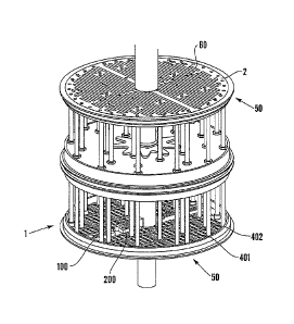
Figure 3a
Figure 3a shows a schematic illustration of a double
acting piston means 1 comprising valve means 50 including:
15 piston face means 2 including multiple sealing ports 60;
retaining plate means 402; valve plate means 401; opening
means 100; and closing means 200.
Figure 3b
Figure 3b shows a valve means 50 comprising opening
means 100 comprising opening spring means 101, opening pin
means 102 and opening housing means 103; a closing means
200 comprising closing spring means 201, closing housing
means 203, trigger means 204 and closing shaft means 207
comprising closing pin means 202, trigger slot means 205
and reset roller 206; drive shaft means 250; stationary
control rod means 300 comprising reset cam means 301 and
trigger stop means 302; valve sealing face means 400;
valve plate means 401; retaining plate means 402; location
pin means 403,404.
The valve sealing face means 400 and the retaining
plate means 402 sandwich the valve plate means 401 between
them such that the valve plate means 401 can slide freely
in a direction parallel to the valve sealing face means
400 when there is no pressure differential across the
valve.
The opening means 100 and the closing means 200 are
CA 02708551 2010-06-09
16
both located on the retaining plate means 402. The opening
pin means 102 and the closing pin means 202 pass through
the valve plate means 401 into a slot in the valve sealing
face means 400. The location pin means 403 and 404 locate
in a recess in the valve sealing face means 400.
All of these items are attached to the drive shaft
means, which can move up and down. There is a stationary
control rod means 300 that is located inside the drive
shaft means 250. On the control rod means 300 are located
a reset cam means 301 and a trigger stop means 302. These
items-are all stationary and the drive shaft means 250 and
attached structure move up and down past these parts.
When the opening pin means 102 is moved in the
direction that compresses the opening spring means 101
then the opening spring means 101 provides a resisting
force that can be used to open the plate valve means 401
via the opening pin means 102 when the pressure
differential across the valve is at or near pressure
equalisation
When the reset roller means 206 runs along a reset
cam means 301 it pushes the closing shaft means 207 into
the closure housing means 203. such that the closure spring
means 201 is compressed and the trigger means 204 drops
into the trigger slot means 205. The reset roller means
206 moves past the reset cam means 301 and the closure
spring means 201 pushes the closing shaft means 207 via
the trigger slot means 205 against the trigger means 204.
In this position the opening means can move a valve means
from the second position to the first position at or near
pressure equalisation.
When the trigger means 204 contacts a trigger stop
means 302 it lifts the trigger means 204 out of the
trigger slot means 205 and the closing spring means 201
moves the closing pin means 202 via the closing shaft
means 207 such that a valve means attached to the closing
pin means 202 will move from the first position to the
second position.
CA 02708551 2010-06-09
17
The closing spring means 201 is stronger than the
opening spring means 101 such that the movement of the
valve means from the first position to the second position
may also 'reload' the opening spring means by compressing
it.
Figure 4a and 4b
Figures 4a and 4b show opening means 100 comprising
opening spring means 101, opening pin means 102 and
opening housing means 103.
When the opening spring pin means 102. is moved in the
direction that compresses the opening spring means 101
then the opening spring means 101 provides a resisting
force that can be used to open the valve means (not shown)
via the opening pin means 102 when the pressure
differential across the valve is at or near pressure
equalisation.
Figure 5a and 5b
Figures 5a and 5b show closing means 200 comprising
closing spring means 201, closing housing means 203,
trigger means 204 and closing shaft means 207 comprising
closing pin means 202, trigger slot means 205 and reset
roller 206.
When the reset roller means 206 runs along a reset
cam means (not shown) it pushes the closing shaft means
207 into the closure housing means 203 such that the
closure spring means 201 is compressed and the trigger
means 204 drops into the trigger slot means 205. The reset
roller means 206 moves past the reset cam means (not
shown) and the closure spring means 201 pushes the closing
shaft means 207 via the trigger slot means 205 against the
trigger means 204. In this position the opening means can
move a valve means from the second position to the first
position at or near pressure equalisation.
When the trigger means 204 contacts a trigger stop
means (not shown) it lifts the trigger means 204 out of
CA 02708551 2010-06-09
18
the trigger slot means 205 and the closing spring means
201 moves the closing pin means 202 via the closing shaft
means 207 such that a valve means attached to the closing
pin means 202 will move from the first position to the
second position.
The closing spring means 201 is stronger than the
opening spring means (not shown) such that the movement of
the valve means from the first position to the second
position may also reload' the opening spring means by
compressing it.