Note: Descriptions are shown in the official language in which they were submitted.
CA 02708635 2010-07-06
TITLE OF THE INVENTION
VERSATILE VALANCE LIGHT FIXTURE
This application claims priority from GB No. 0911830.8
FIELD OF THE INVENTION
The present invention relates generally to valance light fixtures and, more
particularly, to
a versatile valance light fixture that is relatively easily customizable to
specific decorative
needs.
BACKGROUND OF THE INVENTION
Valance light fixtures are known in the art and are used to add accent or
ambiance
lighting behind a curtain headrail, around the periphery of ceilings, on top
surface
portions of kitchen cabinets, and the likes.
Valance light fixtures of the prior art generally take the form of elongated
neon light
fixtures or elongated light strip fixtures comprising solid state, light
emitting diodes, or
LED's.
The typically elongated housing of the valance light fixtures is generally
directly fixed to a
support structure, such as a wall portion, a windowsill, or the like, using
conventional
CA 02708635 2010-07-06
fastening means such as screws, nails, construction grade staples, or the
like. Thus,
once a valance light fixture is fastened to a support structure, it is
generally not easily
removed for maintenance reasons such as, for examples, a thorough cleaning, a
repair
or a replacement procedure, without using hand tools.
The valance light fixtures of the prior art generally emit light in a fixed
direction that is not
easily customizable. For examples, they generally either emit light along one,
two or
three longitudinal sides. Thus, to satisfy varied decorative needs of end
clients, the
factories or home hardware stores have to keep a large inventory of valance
light
fixtures that are emitting light in various directions.
Furthermore, valance light fixtures of the prior art made of LED light strips
that generally
emit light in a single fixed color that is not easily customizable, unless the
valance light is
equipped with more expensive light strips comprising LED's of various colors
that are
controlled by custom electronic control circuits.
Against this background, there exist a need for a new and improved valance
light fixture
that avoids the aforementioned disadvantages.
SUMMARY OF THE INVENTION
It is a general object of the present invention to provide a new and improved
valance
light fixture. According to a preferred embodiment of the present invention,
the valance
light fixture generally includes an electrically powered elongated light
emitting member,
and a pair of differently shaped and configured mounting brackets, for
mounting the light
emitting member to a surface portion of a support structure.
CA 02708635 2010-07-06
The elongated light emitting member is generally represented by an assembly
comprising an elongated tubular housing closed at each distal ends with
suitably
adapted end caps. At least one of the end caps is suitably adapted with an
aperture for
receiving therethrough a power cable for powering the fixture.
The elongated tubular housing may as well be closed at both ends with
identical end
caps having an aperture, as described above, for allowing a plurality of light
emitting
members to be serially interconnected with interstitial power cables, in a
daisy chain
configuration.
The elongated tubular housing has a substantially square-shaped cross-section,
thus
having four elongated longitudinal surfaces facing outwardly thereof. Three of
the
longitudinal surface are made of a transparent, or at least translucent
plastic material,
while the fourth longitudinal surface is provided with a longitudinally
extending groove
adapted to be engaged, in a snap-fit relation, with a mounting portion of the
mounting
brackets described above.
Thus, the light emitting member, in cooperative relation with the mounting
brackets
described above, may be mounted such that its distal transparent surface is
directed
perpendicularly outwardly, relative to the mounting surface of the support
structure, or in
a parallel direction relative to the latter.
The elongated tubular housing comprises an inner, elongated channel member
that is
extending substantially the length of the housing, and which serves as a
support
structure for at least one, and possibly up to three elongated LED light
strips therein.
Thus, between one and three elongated LED light strips may be disposed
longitudinally
along selected transparent longitudinal surfaces of the tubular housing.
CA 02708635 2010-07-06
Furthermore, the elongated channel member serves also as a strengthening
structural
element for the light emitting member.
The tubular housing member, the end caps and the mounting support brackets are
preferably made of a suitably rigid plastic material using conventional
extruding or
injection molding processes. The elongated channel member may be preferably
made of
a suitably rigid material whose rigidity is not significantly affected by the
accumulated
heat that may be generated by high intensity LED light strips within the
tubular housing
member. For example, the channel member may be made of aluminum, a suitable
metal
alloy, a suitable polymer, glass, or a composite material, that is preferably
light weight
and rust proof.
Thus there is provided a versatile valance light fixture having a light
emitting member
that can be easily removed for maintenance or replacement, as well as being
relatively
easily customizable in terms of the direction and the color of the light that
it is emitting
toward its surrounding space.
Other advantages and novel features of the present invention will be more
apparent from
the following drawings and detailed description.
BRIEF DESCRIPTION OF THE DRAWINGS
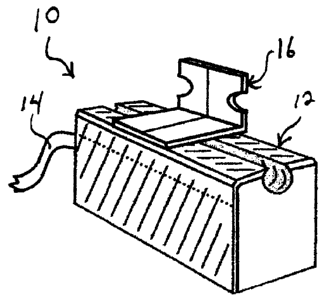
FIG. 1 is a perspective view of a versatile valance light fixture, according
to the present
invention;
FIG. 2A is a perspective view of an elongated housing member;
FIG. 2B is a distal end plan view of the elongated housing member of FIG. 2A;
FIG. 3 is a distal end plan view of the versatile valance light fixture of
FIG. 1, here shown
CA 02708635 2010-07-06
having an end cap removed;
FIG. 4 is a distal end plan view of an elongated support channel having a
substantially
U-shaped cross-section;
FIG. 5 is a distal end plan view of the elongated support channel of FIG. 4,
here shown
with three elongated light strips inserted longitudinally in a corresponding
number of
suitably shaped, elongated side grooves provided along the three outer
longitudinal
sides of the elongated support channel of FIG. 4;
FIG. 6 is a front plan view of a conventional LED light strip;
FIG. 7 is a perspective view of the elongated support channel of FIG. 4, here
shown
having a portion of a LED light strip slidably inserted in one of the
elongated side
grooves of the elongated support channel of FIG. 4;
FIG. 8 is a perspective inner view of a first end cap provided with an inner
aperture for
receiving the wire ends of an external power source;
FIG. 9 is a perspective inner view of a second, closing end cap;
FIG. 10 is an inner plan view of the first end cap shown in FIG. 8;
FIG. 11 is a side plan view of the second end cap shown in FIG. 9;
FIG. 12 is a side plan view of the first end cap in FIG. 8, here shown with a
portion of a
power cable having a suitably configured and shaped distal end inserted in the
aperture
provided therethrough;
FIG. 13 is an inner plan view of the closing end cap of FIG. 9;
FIG. 14 is a perspective view of a 90 degree mounting bracket;
CA 02708635 2010-07-06
FIG. 15 is a side plan view of the 90 degree mounting bracket of FIG. 14;
FIG. 16 is a front plan view of the 90 degree mounting bracket of FIG. 14;
FIG. 17 is perspective view of a 180 degree mounting bracket;
FIG. 18 is a side plan view of the 180 degree mounting bracket of FIG. 17.
DETAILED DESCRIPTION OF THE INVENTION
FIG. 1A shows various aspects of a preferred embodiment of a versatile valance
light
fixture 10 according to the present invention.
The versatile valance light fixture 10 generally includes an elongated light
emitting
member 12, a power cable 14, for powering the light emitting member 12, and at
least
one mounting bracket 16, adapted for mounting the light emitting member 12 to
a
support structure such as, for examples, a wall surface, a windowsill, a top
surface
portion of a kitchen cabinet, or the likes (not shown).
As it will be described in details further below, the versatile valance light
fixture 10 may
be mounted to a support structure using at least one, but preferably a
plurality of
mounting brackets 16. Furthermore, as best illustrated in FIGS. 14 to 18
inclusively, the
versatile valance light fixture 10 may be mounted to a support structure using
at least
one of two differently configured mounting brackets, namely mounting brackets
16A and
16B.
The light emitting member 12 is represented by an assembly that generally
includes an
elongated housing member 18, as best illustrated in FIGS. 2A and 2B, an
elongated
support channel 20 having a substantially U-shaped cross-section, as best
illustrated in
CA 02708635 2010-07-06
FIGS. 4 and 7, and at least one, and up to three elongated LED light strips
22, such as
illustrated in FIG. 6.
The light emitting member 12 further includes a first end cap 24 provided with
an inner
aperture 26, as illustrated in FIGS. 8 and 10, and a second, closing end cap
28, as
illustrated in FIGS. 9 and 13. As it will be described in details more below,
in some
embodiments, the light emitting member 12 may include two end caps 24 having
an
inner aperture 26 instead of one end cap 24 and one end cap 28 as described
above.
The light emitting member 12 still further includes a power cable 14 having a
first distal
end adapted to be inserted through the inner aperture 26 of an end cap 24, as
illustrated
in FIG. 12, and its opposite distal end being provided with a suitable power
supply unit
(not shown) conventionally used for indoor lighting fixtures.
FIGS. 2A and 2B show a tubular and substantially elongated housing member 18
having
a substantially square shaped cross-section. The square shaped cross-section
of the
housing member 18 defines a longitudinal mounting surface 30, a pair of
oppositely
disposed, longitudinal side surfaces 32 and 34, and a distal longitudinal
surface 36.
Substantially centered along the longitudinal mounting surface 30 there is
provided a
longitudinal mounting groove 40 extending inwardly relative to the surface 30,
and
defining a groove therein having a substantially near-circular cross-section.
The
longitudinal mounting groove 40 is adapted for resiliently engaging with a
suitably
shaped and configured mounting member of the mounting brackets 16A and 16B.
Housing member 18 is preferably represented by a single piece element made of
a
suitably rigid plastic material using a conventional extruding or injection
molding process.
As best illustrated in FIGS. 2B and 3, the mounting surface 30, including the
longitudinal
mounting groove 40 and relatively small, adjacent portions of the longitudinal
side
CA 02708635 2010-07-06
surfaces 32, 34, are preferably made of an opaque material, while the rest of
the
longitudinal side surfaces 32, 34 and the distal longitudinal surface 36 are
made of a
transparent, or at least a translucent material for allowing light to emit
outwardly
therefrom.
FIGS. 4, 5 and 7 show various aspects of an elongated channel member 20 having
a
substantially U-shaped cross-section.
The overall cross-sectional dimensions of the U-shaped channel member 20 are
suitably
sized and shaped such that the channel member 20 may be freely longitudinally
inserted
through an open end of the tubular housing member 18, with its distal
longitudinal ends
42 being in register with the longitudinal spaces along either sides of the
protruding inner
surface defining the mounting groove 40, as illustrated in FIG. 3.
The three longitudinal outer surfaces 44, 46 and 48 of the U-shaped channel
member 20
are provided with longitudinal inner grooves 50 having a substantially
rectangular cross-
section. The longitudinal inner grooves 50 are each suitably sized and shaped
for freely
slidably receiving therein the rear portion of an elongated LED light strip
22, as illustrated
in FIGS. 3, 5 and 7.
The elongated U-shaped channel 20 is preferably made of a suitably rigid
material
whose rigidity is not significantly affected by the accumulated heat that may
be
generated by high intensity LED light strips 22 inserted in a fully assembled
and
powered versatile valance light fixture 10. For example, the U-shaped channel
member
20 may be made of aluminum, a suitable metal alloy, a suitable polymer, glass,
or a
composite material, that is preferably light weight and rust proof.
CA 02708635 2010-07-06
Thus, the U-shaped channel member 20, which serves as a positioning element of
the
LED light strips 22 within the housing member 18, also serves as a
strengthening
structure element of an assembled valance light fixture 10.
An elongated LED light strip 22, as illustrated in FIG. 6, may be any
conventional and
commercially available LED light strip element having a suitable shape and
size for
allowing the light strip to be freely slidably engaged along the elongated
inner grooves
50 of the U-shaped channel member 20.
A typical LED light strip 22 of the prior art, as illustrated in a front plan
view in FIG. 6,
and shown in a perspective partial view in FIG. 7, is generally represented by
a
substantially elongated printed circuit board 52 having soldered on a front
side a plurality
of light emitting diodes 54, or LED's, that are equidistantly disposed
therealong.
FIGS. 8 to 13 inclusively show various aspects of a first end cap 24 provided
with an
aperture 56, and a second, closing end cap 26.
First end cap 24 may be represented by a single piece element having a plate
portion 58
defining an inner side 60 and an outer side 62, and whose outer shape and
dimensions
are substantially identical to the cross-sectional outer shape and dimensions
of the
elongated housing member 18, including the semi-circular groove portion of the
latter. A
relatively short tubular portion 64, having a substantially identical but
relatively smaller
cross-section as the plate member 58, here again, including the semi-circular
groove
portion, has a first end integrally formed substantially centrally on the
inner surface 60 of
the plate member 58, and the opposite end extending perpendicularly therefrom.
Thus, a
relatively small abutting ledge 66 is formed about the periphery of the plate
member 58.
Furthermore, the short tubular form 64 has an outer cross-sectional shape and
dimensions allowing the latter to be slidably inserted, in a snug fit
relation, within an
CA 02708635 2010-07-06
open end of the elongated housing member 18 until the protruding periphery, or
abutting
ledge 66 of the plate member 58 firmly abuts against the distal end thereof,
thus forming
an end cap to the housing member 18.
As best mentioned above, and illustrated in FIGS. 8, 10 and 12, the end cap 24
is
provided with an inner aperture 56 for receiving therethrough a distal end of
a power
cable 14 whose end wires 68 may be typically soldered to electrical contact
points (not
shown) provided at a distal end of a LED light strip 22 positioned inside the
light emitting
member 12.
Furthermore, a portion of the outer shielding, proximal the distal end of the
power cable
14, is preferably suitably shaped and sized such that it may be resiliently
engaged about
the inner periphery of aperture 56 of the end cap 24, for providing a
sufficient
mechanical retention between the power cable 14 and the assembled light
emitting
member 22.
The second, closing end cap 26 is substantially identical to the first end cap
described
above, except that it is not provided with an aperture. Closing end cap 26 is
mainly for
the purpose of sealingly enclosing the distal end of an assembled U-shaped
channel
member 20 and LED light strips 22 combination within the elongated housing
member
18.
The end caps 24 and 26 are preferably represented by single piece elements
made of a
suitably rigid plastic material using a conventional injection molding
process.
The overall length of the U-shaped channel member 20 and the LED light strip
or strips
22 may be preferably substantially equal. An assembled U-shaped channel member
20
and LED light strip 22 combination has a suitable overall length that is
relatively shorter
than the length of an elongated housing member 18, for allowing the channel
member
CA 02708635 2010-07-06
20 and light strip 22 combination to be enclosed within the housing member 18,
between
the end caps.
Thus, an assembled elongated light emitting member 12 may include a U-shaped
channel member 20, provided with at least one, and up to three LED light
strips 22, that
is inserted in a housing member 18, with a power cable 14 and end cap 24
combination
for closing a first distal end, and an end cap 26 for closing the opposite
distal end
thereof.
In an alternate preferred embodiment, the closing end cap 26 may be replaced
with an
additional power cable 14 and end cap 24 combination, for allowing the
connection in
series of a plurality of light emitting members 12 in a daisy chain
configuration.
FIGS. 14 to 18 inclusively, show various aspects of two differently shaped and
configured mounting brackets, namely a first mounting bracket 16A and a second
mounting bracket 16B.
FIGS. 14, 15 and 16 inclusively, show the first mounting bracket 16A that is
generally
represented by a relatively short right angle member 70 defining a first
mounting portion
72 and a second mounting portion 74.
The first mounting portion 72 is provided with suitable mounting means such
as, for
example, a plurality of mounting holes or lateral recesses 76, for rigidly
fixing the
mounting bracket 16A against a mounting surface portion of a support structure
using
preferably flat-head screws, nails, or the like.
The second mounting portion 74 is provided, along its outer surface 78
thereof, with a
mounting member 80 suitably shaped and sized for resiliently engaging within
the
longitudinal mounting groove 40 of the elongated housing member 18. The
mounting
CA 02708635 2010-07-06
member 80 is generally represented by a substantially cylindrically-shaped
member
having a C-shaped cross-section, and a longitudinal side portion, opposite the
open side
portion, that is integrally formed centrally longitudinally along the outer
surface of the
second mounting portion 74, as best illustrated in FIGS. 15 and 16.
The C-shaped cross-section of the mounting member 80 is suitably sized such
that it
exerts a sufficiently spring biased outward action against the inner
cylindrical surface of
the mounting groove 40 for resiliently retaining the mounting bracket therein.
Thus, the first mounting bracket 16A may be used for rigidly fixing a light
emitting
member 12, as described above, to a mounting surface portion of a support
structure
such that the distal longitudinal surface 36 of the light emitting member 12
may be
projecting light in a substantially parallel direction relative to the
mounting surface
portion.
FIGS. 17 and 18 show a second mounting bracket 16B that is generally
represented by
a mounting plate member 82 defining a front side surface 84, a rear side
surface 86, an
upper edge 88, and a lower edge 90. The second mounting bracket 16B is
provided with
suitable mounting means such as, likewise the first mounting bracket 16A
described
above, a plurality of mounting holes or lateral recesses 76, for rigidly
fixing the mounting
bracket 16B against a mounting surface portion of a support structure using
preferably
flat-head screws, nails, or the like.
Also likewise the first mounting bracket 16A described above, the second
mounting
bracket 16B is provided with a cylindrically-shaped mounting member 92 having
a C-
shaped cross-section, and which has a longitudinal side portion integrally
formed and
disposed along a front side 84 surface portion substantially proximal and
parallel to the
upper edge 88 of the mounting plate member 82.
CA 02708635 2010-07-06
Substantially centrally disposed proximal the lower edge 90 of the mounting
plate
member 82 there is provided a substantially triangular-shaped support member
94 that
is extending outwardly, relative to the front side surface 84, and slightly
angularly toward
the upper edge 88 of the plate member 82, as best illustrated in FIG. 18. The
triangular
support member 94 is suitably configured and shaped to support a downwardly
facing,
longitudinal side portion 32 or 34 of a light emitting member 12, when the
latter is fixed
substantially horizontally to a vertical support structure using the second
mounting
bracket 16B.
Thus, the second mounting bracket 16B may be used for rigidly fixing a light
emitting
member 12 to a mounting surface portion of a support structure such that the
distal
longitudinal surface 36 of the light emitting member 12 may be projecting
light
perpendicularly outwardly relative to the mounting surface portion.
The mounting brackets 16A and 16B are preferably made of a suitably rigid
plastic
material using a conventional injection molding process.
Preferably, an elongated light emitting member 12 may be fixed to a support
structure
by, first, rigidly fixing thereto at suitable locations a plurality of one of
the two, or a
suitable combination of both mounting brackets 16A and 16B, using fastening
elements
such as flat-head screws. Second, the mounting surface 30 of the light
emitting member
12 is aligned such that the semi-circular mounting groove 40 is substantially
aligned and
abutting against the protruding portion of the mounting members 80 and/or 92
of the
mounting brackets 16A and/or 16B respectively. Finally, as illustrated in
FIGS. 1 and 3,
the mounting groove 40 is engaged in a snap-fit relation onto the mounting
members 80
and/or 92, by firmly pressing on the portions of the light emitting member 12
corresponding to the position of each mounting members.
CA 02708635 2010-07-06
Thus there is described a versatile valance light fixture 10 having a light
emitting
member 12 that can be easily removed for maintenance or replacement, as well
as
being relatively easily customizable in terms of the direction and the color
of the light that
it is emitting toward its surrounding space. Furthermore, a plurality of
versatile valance
light fixture 10 of the present invention can be easily connected in a daisy
chain
configuration.
Although the above description contains many specificities, these should not
be
construed as limitations on the scope of the invention but as merely providing
one
illustration of the presently preferred embodiment of this invention.