Note: Descriptions are shown in the official language in which they were submitted.
CA 02708881 2010-06-10
S P E C I F I C A T I O N
ABSORBENT ARTICLE
TECHNICAL FIELD
[0001]
The present invention relates to absorbent articles and more
particularly to absorbent articles such as disposable diapers,
toilet-training pants or incontinent briefs.
RELATED ART
[0002]
Disposable diapers provided with skin-contact sheets
serving to protect the wearers' skin from contact with body waste
are known, for example, from the disclosure of JP2007-105298A
(PATENT DOCUMENT 1). According to the disclosure of PATENT
DOCUMENT 1, the diaper comprises a topsheet, a backsheet, an
absorbent structure sandwiched between these topsheet and
backsheet and a skin-contact sheet disposed on the side of the
topsheet facing a wearer's skin wherein the skin-contact sheet
is provided with at least one through-hole adapted to guide body
waste to the side of the topsheet and elastic members attached
CA 02708881 2010-06-10
-2-
under tension to the skin-contact sheet so as to surround the
through-hole. Such skin-contact sheets adopted by these two
examples of prior art are adapted to raise themselves from the
topsheets and to come in contact with the wearers' crotch skin
under the effect of the elastic members so as to protect the
wearer's skin from contact with body waste.
PATENT DOCUMENT 1: JP2007-105298A
DISCLOSURE OF THE INVENTION
PROBLEM TO BE SOLVED BY THE INVENTION
[0003]
In the diaper disclosed in PATENT DOCUMENT 1, a through-hole
giving passage to urine and a through-hole giving passage to feces
are provided. However, the diaper may displace on a wearer's body
depending on a posture of the wearer and consequently sometimes
urination occurs directly on the skin contact sheet. Urine
staying on the skin contact sheet may cause stuffiness and any
skin trouble such as eczema.
[0004]
In view of the problem as has been described just above,
it is a principal object of the invention to prevent urine on the
barrier sheet from coming in contact with a wearer's skin and
CA 02708881 2010-06-10
-3-
thereby to alleviate skin trouble such as eczema the wearer might
suffer from.
MEASURE TO SOLVE THE PROBLEM
[0005]
The invention relates to an improvement in the absorbent
article comprising a chassis having a front-to-rear direction and
a transverse direction, sides facing a wearer's skin and wearer's
clothes, respectively, a front waist region, a rear waist region
and a crotch region extending between the front and rear waist
regions, and a liquid-absorbent structure disposed on the crotch
region, and a barrier sheet provided in the crotch region on the
side of the chassis facing a wearer's skin and being able to be
spaced from the chassis.
[0006]
The absorbent article according to the invention is
characterized in that the barrier sheet has a pair of lateral zones
extending in the front-to-rear direction and opposed to each other
in the transverse direction, a middle zone connecting the lateral
zones to each other, front and rear ends extending in the
transverse direction and opposed to each other in the
front-to-rear direction and barrier sheet's elastic members
CA 02708881 2010-06-10
-4-
extending in the front-to-rear direction and attached under
tension to the barrier sheet and opposed to each other in the
transverse direction wherein the front and rear ends are
permanently bonded to the side of the chassis facing a wearer's
skin and the liquid-absorbent structure is adapted to be bowed
in a direction from the crotch region toward the front and rear
waist regions and thereby to form a pocket between the barrier
sheet and the liquid-absorbent structure, and to form
through-holes defined by the pair of lateral zones and the middle
zone so that body waste can pass the through-holes into the pocket,
and the pair of lateral zones lying outside the middle zones as
viewed in the transverse direction are formed with folds along
which the barrier sheet is convex toward the chassis.
[0007]
According to one preferred embodiment, the folds are formed
by thermal processing, e.g., fusing the portions of the lateral
zones.
[0008]
According to another preferred embodiment, the folds are
formed by folding portions of the lateral zones so as to be convex
toward the side of the chassis and bonding the opposite surfaces
CA 02708881 2010-06-10
-5-
of the portions folded in this manner.
[0009]
According to still another preferred embodiment, the
barrier sheet includes the slits formed by partially cutting off
the folds.
[0010]
According to yet another preferred embodiment, the liquid
-absorbent structure is bonded to the lateral zones of the barrier
sheet via the joint zones and these joint zones lie inside the
side edges as viewed in the transverse direction wherein the side
edges are extending in the front-to-rear direction of the
liquid-absorbent structure and opposed to each other in the
transverse direction so that the exposed portions not covered with
the barrier sheet appear along the side edges of the
liquid-absorbent structure when the barrier sheet is spaced upward
from the chassis.
[0011]
According to further another preferred embodiment, the
through-hole comprises the front through-hole defined on the front
side with respect to the middle zone as viewed in the front-to-rear
direction and the rear through-hole defined on the rear side with
CA 02708881 2010-06-10
-6-
respect to the middle zone as viewed in the front-to-rear direction
wherein the barrier sheet's elastic members are attached to the
barrier sheet along the front and rear through-holes and,
respectively include the convex segments extending toward the
longitudinal center line bisecting the dimension of the barrier
sheet in the middle zone and wherein the folds lie outside the
barrier sheet's elastic members as viewed in the transverse
direction.
EFFECT OF THE INVENTION
[0012]
According to the invention, the lateral zones of the barrier
sheet defined just outside the middle zone as viewed in transverse
direction are formed with the folds extending in the transverse
direction so that the barrier sheet can be folded convexly toward
the chassis along these folds. Such unique arrangement ensures
that, even when urination occurs onto the barrier sheet, urine
moving to the middle zone defined by these folds is reliably guided
thereby toward the chassis. In this way, urine is prevented from
staying on the barrier sheet and causing any skin trouble.
[0013]
According to the embodiment of the invention wherein the
CA 02708881 2010-06-10
-7-
folds are formed fusing the portions of the lateral zones of the
barrier sheet so as to form the grooves, the folds are guided so
as to be easily folded along the grooves.
[0014]
According to the embodiment of the invention wherein the
barrier sheet include the slits formed by partially cutting off
the folds, the zones in which the slits are formed have a
sufficiently low rigidity to facilitate the barrier sheet to be
folded along the folds. The slits allow urine staying on the
barrier sheet to be quickly through the slits to the
liquid-absorbent structure.
[0015]
According to the embodiment of the invention wherein the
barrier sheet is bonded to the liquid-absorbent structure via the
joint zones, and the joint zones lie inside the side edges of the
liquid-absorbent structure and therefore, when the barrier sheet
is spaced upward from the liquid-absorbent structure, the portion
of the liquid-absorbent structure not covered with both the
barrier sheet and leak-barrier cuffs is defined between the side
edges and the joint zones. Thus, urine otherwise staying on the
barrier sheet can be guided along the folds to the liquid-absorbent
CA 02708881 2010-06-10
-8-
structure and absorbed therein.
[0016]
According to the embodiment of the invention wherein the
through-hole formed to the barrier sheet comprises the front
through hole defined on the front side with respect to the middle
zone and the rear through-hole defined on the rear side with
respect to the middle zone wherein the barrier sheet's elastic
members are attached to the barrier sheet along the front and rear
through-holes and therein the folds lie outside the barrier
sheet's elastic members, contractile force of the barrier sheet's
elastic members directed from the lateral zones toward the
longitudinal center line is exerted on the middle zone, further
facilitating the lateral zones along the folds. Furthermore,
since the barrier sheet's elastic members has a convex segment
in the middle zone of the barrier sheet, the barrier sheet's
elastic members cause the middle zone into better contact with
the wearer's skin and the barrier sheet is folded along the folds
so as to stop from the middle zone toward the liquid-absorbent
structure. Consequently, urine staying on the barrier sheet can
be quickly guided from the middle zone to the liquid-absorbent
structure via the lateral zones.
CA 02708881 2010-06-10
-9-
[BRIEF DESCRIPTION OF THE DRAWINGS]
[0017]
[FIG. 1] Fig. 1 is a perspective view of a diaper as a first
embodiment according to the invention.
[FIG. 2] Fig. 2 is a sectional view taken along a line II-II in
Fig. 1.
[FIG. 3] Fig. 3 is a plan view showing the diaper of Fig. 1 as
has been flatly developed.
[FIG. 4] Fig. 4 is a schematic diagram illustrating an important
part as seen in Fig. 3.
[FIG. 5] Fig. 5 is a sectional view taken along a line V-V in
Fig. 4.
[FIG. 6] Fig. 6 is a schematic diagram illustrating the important
part in Fig. 4 as put on a wearer's body.
[FIG. 7] Fig. 7 is a sectional view taken along a line VII-VII
in Fig. 4.
[FIG. 8] Fig. 8 is a schematic diagram illustrating an important
part in the second embodiment according to the third aspect of
the invention.
[IDENTIFICATION OF REFERENCE NUMERALS USED IN THE DRAWINGS]
[0018]
CA 02708881 2010-06-10
-10-
1 diaper
2 chassis
3 barrier sheet
4 leak-barrier cuffs
5 side facing wearer's skin
6 side facing away from wearer's skin
7 front waist region
8 rear waist region
9 crotch region
10 liquid-absorbent structure
27 front end
28 rear end
29 pocket
30 lateral zone
31 lateral zone
32 middle zone
33 front through-hole
34 rear through-hole
39 barrier sheet's elastic members
40 curved segments
43 joint zones
CA 02708881 2010-06-10
-11-
44 side edge
45 side edge
49 side edges
50 cuffs' elastic members
54 slits
DESCRIPTION OF THE BEST MODE FOR WORKING OF THE INVENTION
[0019]
The present invention will be exemplarily described
hereinafter on the basis of a disposable diaper taken as typical
embodiments of an absorbent article according to the present
invention.
[0020]
<First embodiment according to the invention>
Figs. 1 through 7 illustrate a first embodiment according
to the invention. Fig. 1 shows a diaper 1 as put on a wearer's
body wherein the diaper 1 is partially cut off for convenience
of illustration. As shown, the diaper 1 comprises a
liquid-absorbent chassis 2, a barrier sheet 3 and leak-barrier
cuffs 4. The chassis 2 is pants-shaped and defined by a transverse
direction X, a vertical direction Y, a longitudinal direction Y,
an inner side 5 facing a wearer's skin, an outer side 6 facing
CA 02708881 2010-06-10
-12-
wearer's clothes, a front waist region 7, a rear waist region 8
and a crotch region 9 extending between said front and rear waist
regions 7, 8. The chassis 2 comprises a topsheet 11, a backsheet
12 and a liquid-impervious leak-barrier sheet 13 sandwiched
between these top- and backsheets 11, 12.
[0021]
The front and rear waist regions 7, 8 respectively have pairs
of side edges 14, 15 put flat and joined together at a plurality
of joints 16 arranged intermittently along the respective side
edges 14, 15 to form seams. In this way, the front and rear waist
regions 7, 8 are joined together along the respective side edges
14, 15 so as to form a waist-opening 18 surrounded by the front
and rear waist regions 7, 8 and a pair of leg-openings 19 surrounded
by the respective rows of joints 16 and the crotch region 9. A
plurality of waist elastic members 20 circumferentially extend
along a peripheral edge of the waist-opening 18 and a plurality
of leg elastic members 21 circumferentially extend along
respective peripheral edges of the leg-openings 19. These
elastic members 20, 21 are sandwiched between the topsheet 11 and
the backsheet 12 and bonded under tension to at least one of these
sheets 11, 12 by means of adhesive (not shown).
CA 02708881 2010-06-10
-13-
[0022]
Fig. 2 is a sectional view taken along a line II-II in Fig.
1 and partially cut away for convenience of illustration. As will
be seen in Fig. 2, the liquid-absorbent structure 10 is disposed
on the inner side 5 of the chassis 2 facing a wearer's skin, the
barrier sheet 3 is disposed on the side of the liquid-absorbent
structure 10 facing the wearer's skin, and the leak-barrier cuffs
4 is disposed on the side of the barrier sheet 3 facing the wearer' s
skin. While the liquid-absorbent structure 10 extends across the
crotch region 9 and further into the front and rear waist regions
7, 8 in the longitudinal direction Y in this embodiment, the
liquid-absorbent structure 10 will effectively function so far
as it extends at least across the crotch region 9. The
liquid-absorbent structure 10 includes a liquid-absorbent panel
23 disposed on the inner surface of the topsheet 11.
[0023]
The liquid-absorbent panel 23 comprises a liquid-absorbent
core 25 wrapped with a liquid-absorbent and -spreadable sheet 24
such as tissue paper and an inner sheet 26 covering the
liquid-absorbent and -spreadable sheet 24. The side of the
liquid-absorbent panel 23 facing wearer's clothes is covered with
CA 02708881 2010-06-10
-14-
the leak-barrier sheet 13 which is disposed on the inner surface
of the backsheet 12 to prevent bodily fluids once absorbed by the
core 25 from leaking out from the diaper 1. The leak-barrier sheet
13 may be bonded directly to the bottom surface of the
liquid-absorbent panel 23.
[00241
The barrier sheet 3 is bonded in the vicinity of its front
and rear ends 27, 28 to the inner sheet 26 by means of adhesion
or sealing. The front end 27 and the rear end 28 are located in
the front waist region 7 and the rear waist region 8, respectively.
In a pants-shaped state as illustrated, the crotch region 9 is
bowed and the barrier sheet 3 is spaced upward from the inner sheet
26 in the longitudinal direction Y under contraction of barrier
sheet's elastic members which will be described later. The front
and rear ends 27, 28 of the barrier sheet 3 are bonded to the inner
sheet 26 so that the barrier sheet 3 as a whole takes a posture
like a hammock being slung. As a result, a pocket 29 is defined
between the barrier sheet 3 and the liquid-absorbent panel 23.
The leak-barrier cuffs 4 are spaced upward from the barrier sheet
3 under contraction of cuffs' elastic members which will be
described later and form a wall extending in the longitudinal
CA 02708881 2010-06-10
- 15-
direction Y.
[0025]
Fig. 3 is a plan view of the diaper 1 as flatly developed
in the longitudinal direction Y as well as in the transverse
direction X after the front and rear waist regions 7, 8 have been
separated from each other along the respective rows of the joints
16 as seen in Fig. 1. In the state of the diaper 1 shown herein,
the respective elastic members are under tension so as to keep
the diaper 1 in the flattened state. The diaper 1 has a
longitudinal center line P-P bisecting a dimension of the diaper
1 in the transverse direction X and a transverse center line Q-Q
bisecting a dimension of the diaper 1 in the longitudinal direction
Y and is bilaterally-symmetric about the longitudinal center line
P-P.
[0026]
The chassis 2 has a concave shape curved inwardly and the
liquid-absorbent panel 223 is rectangular and laminated on the
topsheet 11 of the chassis 2. The barrier sheet 3 comprises a
pair of lateral zones 30, 31 opposed to and spaced from each other
in the transverse direction X and a middle zone 32 extending
between these lateral zones 30, 31 wherein the middle zone 32 is
CA 02708881 2010-06-10
-16-
located in the crotch region 9. The lateral zones 30, 31 cooperate
with the middle zone 32 to form front and rear through-holes 33,
34. The front through-hole 33 has a substantially U-shape
extending from the middle zone 32 into the front waist region 7
and the rear through-hole 34 has a substantially U-shape extending
from the middle zone 32 into the rear waist region 8. The front
through-hole 33 is defined by a pair of inner side edges 35 of
the respective lateral zones 30, 31 and a curved margin of closure
36 connecting these inner side edges 35 to each other. The rear
through-hole 34 is defined by a pair of inner side edges 37 of
the respective lateral zones 30, 31 and a curved margin of closure
38 connecting these inner side edges 37 to each other. These
curved margins of closure 36, 38 of the front and rear
through-holes 33, 34 are defined by the middle zone 32 of the
barrier sheet 3.
[0027]
The leak-barrier cuffs 4 comprise a pair of sheets extending
in the longitudinal direction Y in symmetric relationship about
the longitudinal center line P-P and formed, for example, by
nonwoven fabric or plastic film which is preferably
liquid-impervious. The leak-barrier cuffs 4 are formed so as to
CA 02708881 2010-06-10
-17-
overlap respective skin-contacting surfaces of the lateral zones
30, 31 of the barrier sheet 3. Each of the leak-barrier cuffs
4 has a dimension in the transverse direction X substantially same
as or slightly larger than a dimension of the individual lateral
zone 30, 31 of the barrier sheet 3 in the transverse direction
X.
[0028]
This diaper 1 may be put on a wearer' s body with the wearer' s
external genital opposed to the front through-hole 33, the
wearer's anus opposed to the rear trough-hole 34 and a zone of
the wearer's skin defined between the external genital and the
anus opposed to the middle zone 32. With the diaper 1 put on a
wearer's body in this manner, the margin of closure 36 of the front
through-hole 33 is preferably positioned aside forward from the
transverse center Q-Q and the margin of closure 38 of the rear
through-hole 34 is preferably positioned just on or in the vicinity
of the transverse center line Q-Q. Thereupon, the liquid-absorbent
panel 23 is bowed in the longitudinal direction Y and the barrier
sheet 3 lifted up into contact with a wearer's skin under
contraction of the barrier sheet's elastic members 39 so that the
pocket 29 (See Fig. 2) may be formed between the barrier sheet
CA 02708881 2010-06-10
-18-
3 and the liquid-absorbent panel 23. In this way, body waste may
be reliably received by the pocket 229 through the front and rear
through-holes 33, 34 and thus prevented from coming in direct
contact with the wearer's skin.
[0029]
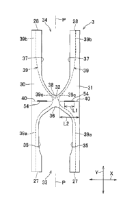
Fig. 4 is a diagram illustrating details of the
liquid-absorbent panel 23, the barrier sheet 3 and the
leak-barrier cuffs 4 but partially cutaway for convenience of
illustration. The lateral zones 30, 31 of the barrier sheet 3
are folded back toward the liquid-absorbent panel 23 and form
folded zones 42, so as to define two-ply structures. The folded
zones 42 are bonded to inner sheet 26 of liquid-absorbent panel
23 via joint zones 43. Each of these two-ply lateral zones 30,
31 contains therein the barrier sheet's elastic member 39 bonded
thereto by means of adhesive (not shown) . Specifically these
barrier sheet's elastic members 39 are attached to the respective
lateral zones 30, 31 under tension in the longitudinal direction
Y.
[0030]
The front and rear through-holes 33, 34 have substantially
U-shapes extending from the middle zone 32 toward the front and
CA 02708881 2010-06-10
-19-
rear waist regions 7, 8 and defined by substantially rectilinear
inner side edges 35, 37 and the curved margins of closure 36, 38.
The barrier sheet' s elastic members 39 are provided along the front
and rear through-holes 33, 34. Specifically, each of the barrier
sheet's elastic members 39 comprises a substantially rectilinear
front segment 39a extending in the vicinity of the inner side edge
35 of the front through-hole 33 and a substantially rectilinear
rear segment 39b in the vicinity of the inner side edge 37 of the
rear through-hole 34. In the middle zone 32 connecting the front
and rear through-holes 33, 234 with each other, the elastic member
39 has a convex segment 239c extending toward the longitudinal
center line P-P.
[0031]
The barrier sheet 3 is provided outside the convex segments
39c as viewed in the transverse direction X with folds 40 extending
in the transverse direction X. These folds 40 are formed by
thermal processing including fusion and application of pressure.
These folds 40 are formed outside the middle zone 32 so as to extend
in the transverse direction X. Each of the folds 40 is dimensioned
in the transverse direction X so as to be substantially the same
as the dimension of the barrier sheet's elastic member 39 as
CA 02708881 2010-06-10
-20-
measured from the convex segment 39c to the side edge of the barrier
sheet 3. As will be seen in Fig. 5 which is a sectional view taken
along a line taken along a line V-V in Fig. 4, said fold 40 is
provided in the form of a groove 41 formed by thermal processing
under a pressure so as to guide operation of folding the barrier
sheet 3.
[0032]
As will be seen in Fig. 4, the joint zones 43 extend from
the front end 27 to the rear end 28 in the longitudinal direction
Y inside the side edges 44, 45 of the liquid-absorbent panel 23
as viewed in the transverse direction X. Specifically, the joint
zones 43 are spaced from the side edges 44, 45, respectively.
These joint zones 43 are typically formed by conventional type
of rubber-based hot melt adhesive but it is also possible to form
these joint zones 243 by means of commonly used means such as sonic
sealing or heat-sealing technique.
[0033]
Each of the leak-barrier cuffs 4 comprises a three-ply sheet
having a Z-shaped cross section. More specifically, the
leak-barrier cuff 4 comprises a first layer 46, a second layer
47 and a third layer 48 laminated one upon another. The first
CA 02708881 2010-06-10
-21-
layer 46 is sandwiched between the liquid-absorbent panel 23 and
the chassis 2. The second layer 47 is folded back from the first
layer 46 onto the side of the barrier sheet 3 facing a wearer's
skin so as to be placed upon the lateral zone 30 or 31. The third
layer 48 is folded back from the second layer 47 onto the side
of the second layer 47 facing the wearer's skin. In this manner,
the leak-barrier cuff 4 is folded back toward the wearer's skin
in the order of the first, second and third layers 46, 47, 48
wherein the first layer 46 and the second layer 47 are placed upon
each other via the liquid-absorbent panel 23 and the second layer
47 is placed directly upon the third layer 48. The third layer
48 is folded back onto itself along a side edge 49 thereof so that
a cuff's elastic member 50 may be attached thereto. The cuff's
elastic member 50 is bonded to this two-ply side edge 49 under
tension in the longitudinal direction Y.
[00341
At front and rear ends 51, 52 of the leak-barrier cuff 4,
the first layer 46 is bonded to the liquid-absorbent panel 23,
the second layer 47 is bonded to the barrier sheet 3 and the third
layer 48 is bonded to the second layer 47. The first layer 46
is bonded to the topsheet 11 of the chassis 2 so as to extend in
CA 02708881 2010-06-10
-22-
the longitudinal direction Y between the front and rear ends 51,
52 and thereby to form a fixed edge. Under contractile force of
the cuff's elastic member 50 exerted on the leak-barrier cuff 4,
the second layer 47 and the third layer 48 are unfolded and thereby
spaced upward from the barrier sheet 3 so as to form a wall as
seen in Fig. 2. Portions of the second layer 47 and the third
layer 48 adapted to be spaced from the barrier sheet 3, i . e . , not
bonded to the barrier sheet 3 is referred to herein as a free edge.
[0035]
Fig. 6 illustrates the barrier sheet 3, the leak-barrier
cuffs 4 and the liquid-absorbent panel 23 when such diaper is put
on a wearer's body. With the diaper put on a wearer's body, as
illustrated, the barrier sheet's elastic members 39 as well as
the cuffs' elastic members 50 contract. Contraction of the
barrier sheet's elastic members 39 causes the liquid-absorbent
panel 23 to be bowed and simultaneously causes the barrier sheet
3 to be spaced upward from the liquid-absorbent panel 23.
Contraction of the cuffs' elastic members 50 causes the free edges
of the second layer 47 as well as the third layer 48 of the
leak-barrier cuffs 4 to be unfolded in the direction in which these
layers are spaced from the liquid-absorbent panel 23 and to be
CA 02708881 2010-06-10
-23-
raised from their collapsed states.
[0036]
When the liquid-absorbent panel 23 is bowed as has been
described above, the barrier sheet 3 bonded thereto is also
subjected to a force tending to bow this barrier sheet 3 in the
longitudinal direction Y. The barrier sheet 3 are formed with
the folds 40 which are, in turn, formed with grooves 41
facilitating the barrier sheet 3 to be folded along the folds 40
as the liquid-absorbent panel 23 is bowed. Thus the barrier sheet
3 is folded so as to be convex toward the liquid-absorbent panel
23. The folds 40 are formed outside the convex segments 39c of
the barrier sheet's elastic members 39 as viewed in the transverse
direction X. Consequentially, contractile force of the barrier
sheet's elastic members 39 directed from the lateral zones 30,
31 toward the longitudinal center line P-P is exerted on the middle
zone 32 of the barrier sheet 3, further facilitating the lateral
zones 30, 31 along the folds 40.
[0037]
Fig. 7 is a sectional view taken along a line VII-VII in
Fig. 4 wherein chain double-dashed lines indicate the diaper put
on a wearer's body as shown in Fig. 6. While Fig. 7 illustrates
CA 02708881 2010-06-10
-24-
the lateral zone 31 of the barrier sheet 3, it will be appreciated
that the lateral zone 230 is similar to the lateral zone 31.
Contraction of the barrier sheet's elastic members 39 causes the
middle zone 32 of the barrier sheet 3 is spaced upward from the
liquid-absorbent panel 23 into contact with a wearer's skin.
Outside the middle zone 32 formed with the folds 40 as viewed in
the transverse direction X, the barrier sheet 3 is folded along
these folds 40 so as to slope from the middle zone 32 toward the
liquid-absorbent panel 23.
[0038]
The barrier sheet 3 is bonded to the liquid-absorbent panel
23 via the joint zones 43. The joint zones 43 lie inside the side
edges 44, 45 of the liquid-absorbent panel 23 as viewed in the
transverse direction X and therefore, when the barrier sheet 3
is spaced upward from the liquid-absorbent panel 23, a portion
of the liquid-absorbent panel 23 not covered with both the barrier
sheet 3 and the leak-barrier cuffs 4, i.e., an exposed portion
53 is defined between the side edges 44, 45 and the joint zones
43. Urine otherwise staying on the barrier sheet 3 can be guided
along the folds 40 to the liquid-absorbent panel 23 and absorbed
therein. In this way, even if urination occurs onto the barrier
CA 02708881 2010-06-10
-25-
sheet 3, such urine can be quickly guided from the barrier sheet
3 to the liquid-absorbent panel 23, the wearer can be protected
from any skin trouble due to urine staying on the barrier sheet
3.
[00391
The joint zones 43 are formed so as to overlap the respective
free edges of the leak-barrier cuffs 4 in collapsed states thereof.
Specifically, the joint zones 43 are located so as to overlap the
second layer 47 and the third layer 48, respectively. If the joint
zones 43 are located so as to overlap the fixed edges, the zones
defined between the joint zones 43 and the side edges 44, 45 will
be covered with the leak-barrier cuffs 4 when the leak-barrier
cuffs 4 rise and the exposed zone 53 of the liquid-absorbent panel
23 will not be formed. In view of this, the joint zones 43 should
be located so as to overlap the free edges.
[00401
Outside the exposed zone 53 of the liquid-absorbent panel
23 as viewed in the transverse direction X, the leak-barrier cuffs
4 raise themselves from the side edges 44, 45 of the
liquid-absorbent panel 23. In this way, urine guided to said
exposed zone 53 can be prevent from leaking out from the diaper.
CA 02708881 2010-06-10
-26-
In the region of the barrier sheet's elastic members 39 overlapping
the leak-barrier cuffs 4, the barrier sheet' elastic members 39
would not come in direct contact with a wearer's skin and skin
irritation can be correspondingly alleviated.
[0041]
According to this embodiment, the folds 40 are formed by
thermal processing. The lateral zones 30, 31 are folded back and
opposed surfaces of the respective lateral zones 30, 31 folded
back in this manner are joined together, for example, by heat
sealing to form folds extending in the transverse direction X.
With applying an adhesive on the side of barrier sheet 3 facing
a wearer's skin, the lateral zones 30, 31 can be folded and fixed
to form folds. There may be provided between the barrier sheet
3 and the inner sheet 26 the partition sheet adapted to partition
the pocket into the front pocket defined in the front waist region
7 and the rear pocket defined in the rear waist region 8 to form
the folds. In this case, one end of the partition sheet is bonded
to the barrier sheet 3 and the other end is bonded to the inner
sheet 26 so that the barrier sheet 3 spaced from the chassis is
pulled toward the chassis in the joint zone of the partition sheet
and the folds are formed in the zone pulled in this manner.
CA 02708881 2010-06-10
-27-
Specifically, in the zone of the barrier sheet 3 pulled in this
manner, the barrier sheet 3 is spaced from the chassis by a distance
less than the remaining zone of the barrier sheet 3. In
consequence, the barrier sheet 3 is formed on its zone pulled
toward the chassis with the fold which is convex toward the chassis.
The barrier sheet 3 having differential fiber fineness also can
be used and therefore differential stiffness to form the fold.
[0042]
While the single fold 40 is provided in the lateral zones
30, 31, respectively, according to this embodiment, in the
respective lateral zones 30, 31 a plurality of folds extending
in parallel one to another can be provided or the single folds
on each of the lateral zones 30, 31 can be connected to each other
to form a single fold 40 continuously extending over the two
lateral zones 30, 31.
[0043]
While the barrier sheet's elastic members 39 including the
convex segments 39c are used according to this embodiment, the
barrier sheet's elastic members 239 comprising two elastic members
39 intersecting with each other in the middle zone 32 or the barrier
sheet' elastic members 39 divided in the longitudinal direction
CA 02708881 2010-06-10
-28-
Y in the middle zone 32 also can be used. While there are provided
the front and rear through-holes 33, 34 according to this
embodiment, one of these front and rear through-holes 33, 34 may
be eliminated or these through-holes may be circumferentially
closed in the front and rear waist regions 7, 8, respectively.
In other words, these through-holes are not limited U-shaped
through-holes but, for example, may be O-shaped, respectively.
[0044]
While the barrier sheet 3 and the leak-barrier cuff 4
respectively comprise single sheets according to this embodiment,
it is possible to form them by adhesively joining a pair of sheets,
respectively. In this case, the barrier sheet's elastic member
39 as well as the cuff ' s elastic member 50 may be sandwiched between
a pair of sheets, respectively. The folds 40 may be formed on one
of these two sheets or on both sheets after they have been laminated
together.
[0045]
<Second embodiment according to the invention>
Fig. 8 illustrates a second embodiment according to the
invention. This embodiment is similar to the first embodiment
except that the barrier sheet is provided with slits 54. The other
CA 02708881 2010-06-10
-29-
features are similar to those in the first embodiment and will
not be described in details.
[0046]
According to this second embodiment, the barrier sheet 3
is formed with slits 54. These slits 54 extend through the barrier
sheet 3 in its thickness direction. The slits 54 are formed by
partially cutting out the respective folds 40 so as to extend on
the respective folds 40 in the transverse direction X. Each of
the slits 54 has a length dimension Li in the transverse direction
X substantially corresponding to 1/2 of a length dimension L2 from
the convex segment 39c of barrier sheet's elastic member 39 to
the side edge of the barrier sheet 3. If the length dimension
L1 of the slit 54 exceeds this, s strength of the barrier sheet
3 will be deteriorated. The fold 40 has a length dimension
substantially same as the length dimension L2.
[0047]
According to this second embodiment, the zones in which the
slits 254 are formed have a sufficiently low rigidity to facilitate
the barrier sheet 3 to be folded. On both sides of the slit 54
in the transverse direction X, the fold 40 is contiguous to this
slit 54. The fold 40 cooperates with the slit 54 to facilitate
CA 02708881 2010-06-10
-30-
the barrier sheet 3 to be folded.
[0048]
The slit 54 extends through the barrier sheet 3 in the
thickness direction, allowing urine staying on the barrier sheet
3 to be guided through the slit 54 to the liquid-absorbent panel
23. Urine staying on the barrier sheet 3 can be more quickly guided
to the liquid-absorbent panel 23 than in the case of the barrier
sheet 3 provided with only the folds 40.
[0049]
While the slit 54 is rectangular according to this
embodiment, the shape of the slit 54 is not limited to this but
may have other various shapes such as an elliptical shape extending
in the transverse direction X. Even when the folds 40 have been
formed by thermal processing, the slits 54 may be formed so as
to overlap the folds 40 to alleviate any skin irritation due to
the presence of the folds 40.
[0050]
According to the invention, the barrier sheet 3 as well as
the leak-barrier cuffs 4 may be formed, for example, by
liquid-impervious and air-permeable nonwoven fabric, the
topsheet 11 as well as the backsheet 12 may be formed, for example,
CA 02708881 2010-06-10
-31-
by air-permeable nonwoven fabric, the leak-barrier sheet 13 may
be formed, for example, by plastic film and the liquid-absorbent
core 25 constituting the liquid-absorbent panel 23 may be formed,
for example, by a mixture of fluff pulp and super-absorbent polymer
particles. All of these materials have conventionally been used
in the related field of technique.