Note: Descriptions are shown in the official language in which they were submitted.
CA 02709163 2010-06-11
WO 2009/076116 PCT/US2008/085320
-1-
LARGE SCALE LED DISPLAY
CROSS-REFERENCE TO RELATED APPLICATIONS
The present application is related to co-pending patent
applications U.S. Serial No. 12/001,277 entitled "Data And Power
Distribution System and Method For A Large Scale Display;" U.S.
Serial No. 12/001,312 entitled "Enumeration System and Method For A
LED Display;" and U.S. Serial No. 12/001,276 entitled "Large Scale
LED Display System," each filed concurrently herewith.
STATEMENT REGARDING FEDERALLY SPONSORED
RESEARCH OR DEVELOPMENT
N/A
TECHNICAL FIELD
The present invention is directed to a large scale display and
more particularly to the LED modules, segments and support structure
for a large scale LED display.
BACKGROUND OF THE INVENTION
Large scale displays on the order of 10 x 20 ft. or 40 x 60 ft. are
known to employ a net formed of intersecting cables to structurally
support a number of pixel units as shown in Temple U.S. Patent
Application Publication No. US 2006/0039142 Al. Because of its
CA 02709163 2010-06-11
WO 2009/076116 PCT/US2008/085320
-2-
flexible nature, this net display may be supported on curved or irregular
surfaces as well as flat surfaces. However, this net display is so flexible
that the pixel units can twist about the cables, impairing the visibility of
the pixels. Moreover, the horizontal cables of the net flex so that the
pixel units become misaligned resulting in distortions in the displayed
image. The pixel units of this net display include a housing for a circuit
board that supports a cluster of red, green and blue LEDs wherein a
potting material seals the circuit board from the environment. U.S.
patent Yoksza et al. 5,410,328 shows similar pixel modules for a large
scale LED display wherein each module is individually removable from
the display by removing a few screws or twisting the module. One wall
of the housing of the pixel module in Yoksza et al. extends beyond the
LEDs so as to provide a sunshade for the module. Another LED module
for a display, as shown in U.S. patent Simon et al. 4,887,074, uses a heat
sinking potting compound in contact with the circuit board supporting
the LEDs and heat spreader plates to dissipate heat from the module
housing.
BRIEF SUMMARY OF THE INVENTION
In accordance with the present invention, the disadvantages of
prior art large scale LED displays have been overcome. The LED
display system of the present invention includes a novel support
structure for a number of LED modules wherein the support structure is
sufficiently flexible so that the display can conform to curved or
irregular surfaces and yet the support structure has sufficient structural
integrity to prevent twisting and sagging of the LED modules,
preventing misalignment of the modules so that a distortion free image
can be displayed.
In accordance with one feature of the present invention, the
display includes a plurality of LED modules wherein each LED module
includes a module housing that supports a plurality of color LEDs. The
CA 02709163 2010-06-11
WO 2009/076116 PCT/US2008/085320
-3-
support structure for the LED modules includes a first pair of parallel
cables; a first set of rigid links, extending between the cables of the first
cable pair; a second pair of parallel cables, the cables of the second cable
pair being parallel to the cables of the first cable pair; and a second set
of rigid links extending between the cables of the second cable pair
wherein each of the LED modules is mounted on one cable of the first
cable pair and one cable of the second cable pair.
In accordance with another feature of the present invention, the
rigid links are H-shaped links that are over-molded onto a pair of cables.
The links are such that they locate the position of the LED modules
along the cables.
In accordance with another feature of the present invention, the
support structure includes a plurality of plates wherein the plates are
mounted on one cable of the first cable pair adjacent to at least one rigid
link of the first set and on one cable of the second cable pair adjacent to
at least one link of the second set wherein a LED module is removably
mounted on a plate.
In accordance with still a further feature of the present invention,
a LED module for a display includes at least two red LEDs; two green
LEDs; two blue LEDs; a circuit board on which the LEDs are mounted
and an over-molded housing encasing the circuit board, the LEDs
protruding from a front surface of the housing and the front surface of
the housing including a plurality of heat sink fins.
In accordance with another feature of the present invention, a
LED display comprises a plurality of linear segments of LED modules
in each of a plurality of columns or rows of the display, each LED
module having a housing supporting a plurality of multi-color LEDs and
each segment including a plurality of LED modules coupled together so
that the LED modules of a segment are removable from the display only
as a group and each segment of LED modules is removable from the
CA 02709163 2010-06-11
WO 2009/076116 PCT/US2008/085320
-4-
display independent of the LED modules of another segment. In this
embodiment the LED display may include individual LED modules that
are connected between segments of LED modules.
In accordance with another feature of the present invention, a
segment of LED modules for use in a display comprises a first electrical
connector fixedly attached to a first end of the segment; a second
electrical connector fixedly attached to a second end of the segment; a
plurality of spaced LED modules connected between the first electrical
connector and the second electrical connector, the spaced LED modules
being connected end-to-end by at least one cable capable of carrying
power and/or data to each of the LED modules; and a further cable
connected directly between the first connector and the second connector
for carrying data directly between the first and second connectors.
These and other advantages and novel features of the present
invention, as well as details of an illustrated embodiment thereof, will be
more fully understood from the following description and drawings.
BRIEF DESCRIPTION OF THE SEVERAL VIEWS OF THE
DRAWINGS
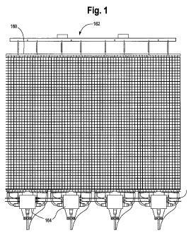
Fig. 1 is a front view of a large scale display in accordance with
one embodiment of the present invention;
Fig. 2 is a partial front view of the display of Fig. 1, illustrating a
number of LED modules mounted on the support structure for the
display of the present invention;
Fig. 3 is a partial perspective view of the support structure for the
display of Figs. 1 and 2;
Fig. 4 is a back view of the support structure depicted in Fig. 3;
Fig. 5 is a partial front view of a pair of master LED modules
and a pair of slave LED modules mounted on the support structure
depicted in Figs. 2-4;
CA 02709163 2010-06-11
WO 2009/076116 PCT/US2008/085320
-5-
Fig. 6 is a perspective view of a segment of slave LED modules
in accordance with one embodiment of the present invention;
Fig. 7 is a side perspective view of the segment of slave LED
modules depicted in Fig. 6 with the housing of one of the modules
removed;
Fig. 8 is a back view of a segment of slave LED modules as
depicted in Fig. 6;
Fig. 9 is a front perspective view of a master LED module in
accordance with one embodiment of the present invention;
Fig. 10 is an illustration of the circuit boards and connectors for
the master LED module depicted in Fig. 9;
Fig. 11 is a back perspective view of the master LED module of
Fig. 9; and
Fig. 12 is a back view of a pair of slave LED module segments
connected between respective master LED modules.
DETAILED DESCRIPTION OF THE INVENTION
A large scale LED display 10 in accordance with the present
invention, as shown in Fig. 1, has height by width dimensions on the
order of 3m x 6m to 24m x 32m or approximately 10 ft. x 20 ft. to 80 ft.
x 105 ft. However, it should be appreciated, that the present invention
can be used for displays that are larger or smaller as well. A display that
is approximately 24m x 32m has 480 pixels x 640 pixels or a total of
307,200 pixels. These large scale LED displays are intended for both
indoor use and outdoor use. The large scale display in accordance with
the present invention is extremely robust and can withstand harsh
outdoor environments while providing distortion free displayed images.
Moreover, segments of the display can be readily replaced.
Each pixel of the display 10 is generated by a module 12 or 14
having two red LEDs 16, two blue LEDs 18 and two green LEDs 20
mounted in a respective housing of the modules 12 or 14 as shown in
CA 02709163 2010-06-11
WO 2009/076116 PCT/US2008/085320
-6-
Fig. 2. A circuit board contained within the housings of the modules 12
and 14 controls the intensities of the red, blue and green LEDs in order
to generate pixels of a large number of different colors as is well known
in the art. Although each of the modules 12 and 14 is depicted in Fig. 2
having pairs of red, green and blue LEDs, the number of red, green and
blue LEDs can vary depending upon the spacing between the individual
modules and the flux density of the individual LEDs. For example,
where the center-to-center spacing between adjacent LED modules is
50mm or greater, one or more red, one or more blue and one or more
green LEDs can provide a light output for the display of 5,000 nits or
greater depending upon the flux density of the LEDs so that the display
is suitable for use outdoors in sunlight. For a display in which the
center-to-center spacing between adjacent LED modules is 75mm or
greater, it is preferable to use a plurality of red LEDs, a plurality of
green LEDs and a plurality of blue LEDs, such as three LEDs of each
color, although the number of LEDs may be reduced depending upon the
flux density of the individual LEDs. It should be appreciated that all of
the LEDs of the modules as well as the entire display may be
monochromatic as well. When monochromatic LEDs are used,
changeable graphics and/or text can be displayed by turning on selected
LEDs or modules. Moreover, to enhance the light output of the
modules, it is preferred that the housing of each of the modules be black
or a dark color as described in detail below. In accordance with another
feature of the invention, however, the color of the housing is selected to
match the color of the structure, such as a building, on which the display
is mounted. Moreover, a single display can employ modules with
different colored housings so that when the LEDs of the display are
turned off, the different colored housings depict a fixed logo, graphic
and/or text message.
CA 02709163 2010-06-11
WO 2009/076116 PCT/US2008/085320
-7-
There are two types of pixel modules employed in the display 10,
master LED modules 12 and slave LED modules 14. Each master
module is associated with a group of slave modules in a segment 24 of
the display. Although Fig. 2 illustrates a segment as including one
master LED module and three slave LED modules for simplicity, in a
preferred embodiment of the present invention, each segment has one
master module and fifteen slave modules to generate sixteen pixels of
the display. It should be apparent, however, that the number of slave
modules can vary from zero to any number depending upon the aspects
of the present invention that are used. In a preferred embodiment, the
segments 24 of the display 10 are linear, extending in a column of the
display 10. However, segments can extend in rows of the display as
well. For a 480 x 640 display having linear segments of sixteen pixels,
there are thirty segments in each column of the display. The segments
are preferably aligned so that each master module is in a row of master
modules. As such, there are thirty rows of master modules with 640
master modules in each row of a 480 x 640 display with fifteen rows of
slave modules between each of the rows of master modules.
The support structure for each of the LED modules 12 and 14 of
the display 10, as shown in Figs. 2-5, includes a first pair of parallel
cables 24 and 26 and a first set of rigid links 28 wherein each link 28
extends between the cable 24 and the cable 26. The support structure for
each of the LED modules 12 and 14 also includes a second pair of
parallel cables 30 and 32 and a second set of rigid links 34 wherein each
link 34 extends between the cable 30 and the cable 32. Each of the LED
modules in a first column of the display 10 is mounted on one cable 26
of the first cable pair and on one cable 30 of the second cable pair
adjacent at least one link 28 from the first set and adjacent at least one
link 34 from the second set. Each of the LED modules in the second
column of the display 10 is mounted on the second cable 32 of the
CA 02709163 2010-06-11
WO 2009/076116 PCT/US2008/085320
-8-
second cable pair and a cable 36 adjacent at least one link 34 of the
second set of links and adjacent at least one link 38 in a third set of links
that extends between cables 38 and 40 of a third cable pair. For a
display having N columns, the support structure includes N+1 pairs of
cables, such as cables 24 and 26, and N+1 sets of rigid links. If the
display has M LED modules in each column, each set of links would
include M links.
In a preferred embodiment, the links 28, 34, 38 are H-shaped
links that are over-molded onto the cables of each cable pair. More
specifically, the two cables of a cable pair are placed in a mold into
which plastic is injected around the cable to form the rigid H-shaped
links connecting the two cables of a pair. A reel to reel molding process
is employed in which the over-molded links are indexed through the
mold and the previously molded links are used to datum and position the
subsequent links. The molding process ensures that the spacing between
the links along the length of the cables is constant. The H-shaped links
are used to precisely and easily locate the LED modules along the
lengths of the cables so that the spacing between the LED modules in a
column and the spacing between the LED modules in a row of the
display 10 remains constant. Moreover, the H-shaped links provide
structural integrity to the cable support structure of the display 10 to
prevent sagging and misalignment of the LED modules when the display
is in use. It is noted that the cables are preferably steel cables that are of
a gauge sufficient to bear the load of all of the LED modules in a
column of the display 10.
More particularly, as depicted in Figs. 3 and 4, the rigid H-
shaped links serve to locate steel back plates 42 of the master LED
modules 12 and steel back plates 44 of the slave LED modules 14. The
back plate 42 of each of the master LED modules has four arms 45-48
on each side of the plate 42 wherein the arms 45-48 are crimped onto the
CA 02709163 2010-06-11
WO 2009/076116 PCT/US2008/085320
-9-
cables of the support structure. The two inner arms 46 and 47 of the
back plate 42 are crimped onto a respective cable on either side of a leg
of the H-link 38 such that the arms 46 and 47 abut the H-link with some
tolerance therebetween. Similarly, the back plate 44 of the slave LED
modules has two arms 50 and 52 on each side of the plate 44 wherein
the arms 50 and 52 are crimped onto the cables of the support structure
on either side of the H-link such that the arms 50 and 52 abut the H-link
with some tolerance therebetween. Because the arms of the back plates
42 and 44 of the LED modules are crimped onto the support cables of
the display 10, the arms and thus the back plates can rotate somewhat
about the cables to provide enough flexibility for the display 10 so that
the display 10 can conform to curved surfaces even though the H-links
cannot rotate about the cables. The rigid H-links and LED module back
plates provide structural integrity for the support structure and prevent
twisting, sagging and misalignment of the LED modules of the display
10. Moreover, the location of the links along the horizontal centerline of
the back plates provides a structure that can be tensioned. This allows
side tensioning of the mesh structure to cause the mesh to conform to a
curved surface or to remove by tension any incidental wrinkles for a flat
configuration.
Both the master LED modules 12 and the slave LED modules 14
are removably mounted on the respective back plates 42 and 44 so that
the individual master LED modules 12 and/or a slave module segment
54 can be removed and replaced after the display 10 is installed. As
seen in Figs. 6-8, a slave module segment 54 includes a first electrical
connector 56 that is fixedly attached to one end of the segment 54 and a
second electrical connector 58 that is connected to a second end of the
segment 54. A number of spaced slave LED modules 14 are connected
between the first and second electrical connectors 56 and 58 via ribbon
cables 60. The ribbon cables 60 carry power and data to each of the
CA 02709163 2010-06-11
WO 2009/076116 PCT/US2008/085320
-10-
slave LED modules 14 of the segment 54 from a master module 12 that
is connected to one of the electrical connectors 56.
As seen in Figs. 7 and 8, each of the electrical connectors 56 and
58 of a slave module segment 54 includes a pair of downwardly
extending rubber or elastomeric prongs 62 and 64. The prongs 62 of the
electrical connector 56 snap through apertures 66 formed in the master
LED module back plate 42. After the electrical connector 56 of the
slave module segment 54 is snapped into the apertures 66 of a master
module back plate 42, each of the slave modules of the segment 54 are
snapped on to respective back plate 44. As a slave LED module 14 is
snapped on to its back plate 44, a pair of module retaining members 72
are forced apart. When the slave module 14 is snapped into its back
plate, the lower edge 73 of the retaining members 72 abuts the tops of a
pair of protrusions 74 formed on the side walls of the slave LED module
housing 100 to retain the slave module 14 securely on the back plate 44.
The electrical connector 58 on the second end of the slave module
segment 54 is inserted in apertures 67 of a master LED module back
plate 42 in the next row of master modules. After the slave module
segment 54 is mounted on the back plates of the cable support structure,
a master LED module 12 is mounted on the back plate 42. Specifically,
a master LED module 12 is mounted on the back plate 42 on top of the
connector 56 with mating connector pins 68 of the module 12 extending
into the apertures 70 of the electrical connector 56. Each of the master
LED modules 12 is secured to a back plate 42 by four screws 78 that
extend through apertures 80 of the back plate 42. In a preferred
embodiment, the back plate 42 of the master LED modules is formed of
steel or the like so that the back plate forms a heat sink that is in contact
with the ground plane 82 of the printed circuit board 128 contained in
the master LED module housing 124 as discussed in detail below. It is
noted, that when the master LED module 12 is bolted onto the back plate
CA 02709163 2010-06-11
WO 2009/076116 PCT/US2008/085320
-11-
42, the over-molded elastomeric pads 86 of the electrical connector 56
are compressed so as to provide a water tight seal between the master
LED module 12 and the electrical connector 56 of the slave module
segment 54 to protect the connector from environmental effects.
The master LED module connected to the slave LED module
segment 54 via the connector 56 provides data and power to the slave
LED modules 14 of the segment 54 via the ribbon connector 60. A
LVDS cable 88 that extends from the first electrical connector 56 and
the second electrical connector 58 provides a direct electrical connection
between a pair of master LED modules 12 and 12' of adjacent segments
24 in a column of the display 10 to allow the master LED modules of
adjacent segments in a column to communicate directly as discussed in
detail in the copending patent application Serial No. 12/001,277 entitled
"Data And Power Distribution System And Method For A Large Scale
Display," filed concurrently herewith and incorporated herein by
reference. Adjacent master LED modules 12 and 12" in a row of the
display 10 communicate directly via a flex cable 90. In a preferred
embodiment, the flex cable 90 overlies a H-link 34 connecting the
support cables 32 and 30 as depicted in Fig. 2.
Each of the slave LED modules 14 includes a housing 100 that is
over-molded about the slave module printed circuit board 102 on which
the LEDs of the module are mounted and about a portion of the ribbon
cables 60 connected to the printed circuit board 102 by a IDC connector
104. Each slave LED module is connected to the ribbon cable in a
common-bus manner so that a failure of any connection does not affect
the other slave modules. In order to over-mold the housings of the slave
LED modules 14, a string of, for example, fifteen printed circuit boards
102 supporting the LEDs for respective slave modules are placed in a
mold wherein the fifteen printed circuit boards are connected by
respective ribbon connectors 60 in a string. Thereafter, a thermoset or
CA 02709163 2010-06-11
WO 2009/076116 PCT/US2008/085320
-12-
thermoplastic resin is injected into the mold to form a casing or housing
100 about the printed circuit boards 102 and ribbon connectors 104. The
over-molded housing of the LED modules provides extremely robust
modules that can withstand harsh outdoor weather. Prior to injecting the
resin to form the housing 100 of the slave LED modules 14, a flash
memory contained on the circuit board 102 is programmed with the
address of the slave LED module. For a slave module segment 54
having fifteen slave LED modules, the slave modules will have an
address of 1 to 15 starting in sequence with the slave LED module that is
closest to the electrical connector 56 to be attached to the master LED
module that will control the slave modules in a segment 24 of the
display. It is noted that, while the printed circuit boards are in the
molding fixture, the electronics on the boards 102 can be tested prior to
over-molding. It is noted, that the mold for the slave LED module
housings supports the printed circuit board 102 for the LEDs at a 10
angle from the back surface 106 of the housing. As such, when the slave
LED module segment 54 is mounted vertically, the LEDs are angled
downward by 10 for better viewing of the pixels generated by the slave
modules when the display is in use. It should be appreciated, however,
that the angle of the LEDs can be 0 to 20 where the LEDs are angled
up, down or to the side depending upon the use of the display.
Each of the housings 100 for the slave LED modules 14 has
integrally formed heat sink fins on a front surface of the housing
between a first column 112 of red, green and blue LEDs and a second
column 114 of red, green and blue LEDs. Placing the heat sink fins 108
between the LEDs of the module, which are actuated to form a single
pixel, does not interfere with the light generated by the LEDs to form the
pixel. It is noted, in a preferred embodiment, the LEDs in the first
column have an order of red, green and blue; whereas the LEDs in the
CA 02709163 2010-06-11
WO 2009/076116 PCT/US2008/085320
- 13 -
second column have an order of green, blue and red so as to provide
better color mixing to generate the various colors of a pixel.
Each of the housings 100 for the slave LED modules 14 also has
integrally formed sunshades 110 that project outwardly above each of
the LEDs 16, 18 and 20. It is noted, that in an alternate embodiment that
does not have the heat sink fins 108 on the front surface of the housing
100, one sunshade 110 may be positioned above each row of LEDs. The
sunshades 110 as well as the black or dark resin used to form the
housing 100 of the LEDs enhances the contrast or conspicuity of the
pixels generated by the modules 14 when the display 10 is used
outdoors.
As shown in Fig. 8, the housing 100 of each of the slave LED
modules 14 is molded so as to form a channel 116 in the back surface
106 of the housing 100. The channel 116 is sufficiently wide so as to be
able to accommodate the cable 88 therein as well as a pair of power
cables 118 and 120. The channels 116 of the housings 100 are aligned
with the ribbon cables 60 so that the LVDS cable 88 and the power
cables 118 and 120 are aligned in back of the ribbon cables 60. Thus,
when viewed from the front of the display 10, the cables 88, 118 and
120 are not readily visible. Further, because the cables 88, 118 and 120
are aligned behind the ribbon cables 60, the display still has open areas
between the modules so that if the display 10 is hung in an open area
outdoors, there is relief for wind. Moreover, the open areas permit
viewing through the display. Such a semi-transparent display will not
block the view out of windows of a building upon which the display is
hung.
The housing 124 for each of the master LED modules is over-
molded about the master module printed circuit boards 126 and 128.
The LEDs 16, 18 and 20 for the master module 12 are mounted on the
printed circuit board 126 which is similar to the printed circuit board 102
CA 02709163 2010-06-11
WO 2009/076116 PCT/US2008/085320
-14-
of the slave LED modules for controlling the illumination of the LEDs
of a module. The printed circuit board 128 of the master LED module
includes additional circuitry for controlling the functions of the master
LED module that are unique thereto, such as extracting the data intended
for the master module and its associated slave LED modules in a
segment 24 of the display as described in the co-pending patent
application Serial No. 12/001,277, entitled "Data and Power Distribution
System And Method For A Large Scale Display," filed concurrently
herewith and incorporated herein by reference. In a preferred
embodiment, the printed circuit board 126 is soldered to the circuit
board 128 at a 10 angle so that when the boards 126 and 128 are placed
in the mold for the master LED module housing 124, the LEDs 16, 18
and 20 will be at a 10 angle to the back surface 130 of the module 12 as
described above for the LEDs of the slave module 14.
The front surface of the housing 124 for each of the master LED
modules 12 is the same as the front surface of the housing 100 for the
slave LED modules 110 so that both types of modules have the same
LED order, the same heat sink fins 108 and the same sunshades 110,
providing a uniform appearance of pixels throughout the display
regardless of whether they are generated by a master or a slave module.
However, the sides and the back surface 130 of the master LED module
housing 124 are different than those of the housing 100 for the slave
modules 102. In particular, the sides 129 and 131 of the master module
housing 124 are formed with projections 132 having apertures 134
therein for the screws 78 that attach the master LED module 12 to the
back plate 42 of the master LED module. The back surface 130 of the
master LED module housing 124 includes a number of integrally formed
heat sinks 136 so as to further aid in the heat dissipation of the master
module. It is noted that the housings for the master LED modules as
well as the housings for the slave LED modules are over-molded with a
CA 02709163 2010-06-11
WO 2009/076116 PCT/US2008/085320
- 15 -
thermally conductive resin. The resin conducts heat away from
components and the geometry of the housing spreads the heat and
provides a maximized surface area for heat transfer. Moreover, the back
plate 42 is thermally and electrically connected to the ground plane on
the master LED module's printed circuit board to allow the back plate
42 to act as an additional and independent heat sink for the master LED
module.
The back surface 130 of the housing 124 of the master LED
module 12 is also formed with two pairs of grooves 138 and 140 through
which power cable connectors 142 and 144 extend. When power cables
118 and 120 are seated in the grooves 138 and 140 of the housing 124,
the prongs of the connectors 142 and 144, pierce the rubber insulation of
the power cables so as to make electrical contact with the cables. The
power cables are continuous and the insulation piercing connectors 142
and 144 are formed with sharp prongs to minimize the force required to
penetrate the rubber insulation on the cables. The preferred insulation is
a thermoplastic elastomer because of its resilience and toughness. This
insulation tends to close around the penetrating prongs forming a seal. It
is noted that when the screws 78 that attach a master LED module 12 to
a back plate 42 are tightened, the prongs of the connectors 142 and 143
are driven into the power cables. A redundant set of power connections
are provided for the master LED modules so that there are two positive
and two neutral connections spread apart as far as possible such that the
system is tolerant to a connection failure. The master LED module 12
also includes Z-axis connectors 148 and 150 surrounded by elastomeric
pads 152. These connectors are commercially available flexible
connectors that are designed to conduct along a single Z-axis. The back
plate 42 compresses the Z-axis connector between contacts on the
printed circuit board 128 and contacts on the flex circuit 90. The flex
circuit 90 is designed as a stripline circuit with conductors and
CA 02709163 2010-06-11
WO 2009/076116 PCT/US2008/085320
- 16-
conductor spacing adjusted to achieve the desired impedance (75 ohms).
The stripline configuration also provides shielding for the data
conductors. The Z-axis connectors connect to the flex cables 90 so as to
allow adjacent master LED modules 12 in a row of a display panel to
communicate directly as discussed above.
In accordance with a preferred embodiment of the present
invention, the display 10 is arranged in a number of panels for easy
deployment. Each panel, may have, for example, sixteen columns
wherein a full height panel has 480 rows, although, each of the display
panels can have any height and width desired. The support cables, 24,
26, 30, 32, 36 and 40 for the LED modules of each display panel are
attached to a steel bar 60 wherein each of the steel bars 160 of a display
are clamped together to support the multiple display panels forming
the display 10. The steel bar 160 is then attached to a support structure
162 which is used to hoist the display 10 on to a support structure such
as a building or frame. Each of the display panels forming the display
10 includes a data hub 164 that provides the video data to the display
panel of the display 10. Power to the display panel 10 may also be
provided to the display 10 through the data hubs 164 so that the data
hubs can monitor the power supply. Details of the data hubs and power
hubs for the display 10 are disclosed in the co-pending patent
application Serial No. 12/001,277, entitled "Data And Power
Distribution System And Method For A Large Scale Display," filed
concurrently herewith and incorporated herein by reference.
The large scale LED display of the present invention is
extremely robust, readily repairable and suitable for outdoor as well as
indoor use. Many modifications and variations of the present invention
are possible in light of the above teachings. Thus, it is to be understood
that, within the scope of the appended claims, the invention may be
practiced otherwise than as described hereinabove.
CA 02709163 2010-06-11
WO 2009/076116 PCT/US2008/085320
-17-
What is claimed and desired to be secured by Letters Patent is: