Note: Descriptions are shown in the official language in which they were submitted.
CA 02709226 2010-06-14
1
Description
Recombiner Element
The invention relates to a recombiner element, in particular for
use in a security system for a nuclear plant, comprising a
plurality of catalyst elements that are arranged in a common
housing and that trigger a recombination reaction with oxygen when
hydrogen is carried along in a feed gas flow, the housing
surrounding the catalyst elements, which are arranged therein, in a
funnel-type way in such a manner that the heat released by the
recombination reaction supports the gas flow inside the housing by
a convection effect.
In a nuclear plant, in particular in a nuclear power plant, the
formation and release of hydrogen gas and carbon monoxide within
the safety container or containment surrounding the reactor core
must be expected when there are breakdowns or accidental situations
in which, for example, an oxidation of zirconium can occur due to
nuclear heating. In particular after a coolant loss problem, large
quantities of hydrogen can be released thereby. As a result,
explosive gas mixtures can be produced inside the contairiment.
Without counter measures, the accumulation of hydrogen in the
containment atmosphere is thereby possible to the extent that the
integrity of the safety container could be endangered when there is
a- random ignition due to the combustion of a large quantity of
hydrogen.
To prevent the formation of explosive gas mixtures of this type in
the containment of a nuclear power plant, various devices or
CA 02709226 2010-06-14
2
procedures are being discussed.
These include, for example,
devices such as catalytic recombiners, catalytic and/or
electrically operated ignition devices or the combination of both
of the aforementioned devices and methods for a permanent
intertization of the containment.
When using an ignition system to remove the hydrogen from the
atmosphere of the containment, a reliable recombination of the
hydrogen with oxygen should be obtained by means of a controlled
combustion. A
significant pressure build-up as a result of a
virulent hydrogen combustion should thereby be safely avoided. An
ignition system of this type is thereby usually designed in such a
way that a reliable ignition of the hydrogen is also already
ensured when the lower ignition threshold of a gas mixture is
exceeded, i.e. in a gas mixture having comparatively low hydrogen
concentration, or when the inertization threshold of about 55% by
volume vapor is fallen below and also at high hydrogen
concentrations.
An ignition system known from EP 289 907 B1 for the controlled
ignition of a hydrogen-containing gas mixture comprises a spark
igniter which can be fed via an integrated energy storage. The
ignition system is thereby provided with an energy storage designed
to be autark, so that no feed lines are required. In this case, in
particular, a drycell battery is provided as energy storage.
However, this ignition system is only suitable for a limited
service life due to the capacity of the integrated energy storage.
Furthermore, this results in fundamentally preventing a flameless
catalytic oxidation due to premature ignition in the concentration
range of e.g. 5 to about 8% by volume. Therefore, an advantageous
CA 02709226 2010-06-14
3
flameless catalytic degradation at higher concentrations and the
simultaneous creation of high temperature regions (> 600 - 900 C)
is excluded.
The range of the flameless catalysis is thus practically reduced to
the non-ignitable range and a premature single ignition with quick
gas displacement processes is already triggered at slight
variations in concentration without enabling an effective counter
ignition to attain short flame acceleration means due to the
lacking high-temperature regions. Furthermore, when there is a
premature excitation of the spark igniter during a breakdown with
subsequent hydrogen release, a controlled ignition of the hydrogen
is only possible to a limited extent. In addition, this ignition
system also does not react until after an ignition delay period has
expired on the release of hydrogen. Also, a long-term operation of
the ignition system, which would be required to cover all feasible
breakdown scenarios, would only be possible with restrictions.
Furthermore, a precautionary excitation of the ignition system
already in the forefield of an anticipated breakdown from an
external station, as for example from the control tower of a power
plant, is not possible.
Moreover, in security systems based exclusively on the use of
ignition processes for hydrogen, e.g. in the form of spark-plug
systems, there is the additional restriction that no hydrogen
decomposition whatsoever can be conducted in vapor-inert
situations.
Accordingly, in systems of this type, hydrogen
accumulating in the safety container can not be completely
combusted until after corresponding vapor condensation. When there
is hydrogen accumulation in vapor, this can lead to comparatively
CA 02709226 2010-06-14
4
high hydrogen quantities or concentrations which are then burned in
a comparatively short time due to the ignition, so that
uncontrolled reaction patterns can arise. In addition, in systems
based exclusively on ignition, it must be taken into consideration
that the ignition could be omitted completely in so-called
"station-black-out" scenarios, i.e. scenarios with complete loss of
the power supply within the containment.
Alternatively or in addition, therefore, so-called passive
autocatalytic recombiners can be arranged in the safety container
or containment of a nuclear plant within the scope of a security
system. These usually comprise suitable catalyst elements which,
in a catalytic manner, trigger a recombination reaction with oxygen
when hydrogen is carried along in a feed gas flow. The catalyst
elements are thereby usually provided with a surrounding housing,
wherein the housing is designed in the manner of a funnel such that
a convection flow occurs automatically within the housing due to
the funnel effect, so that the gas mixture is conveyed reliably
along the respective catalyst element and the catalytic
recombination reaction can be maintained in this way. The actual
catalytic elements are hereby arranged primarily vertically and to
a great extent parallel within the respective catalytic recombiner
element in order to produce and promote the upward lift between the
elements.
When hydrogen occurs in the gas mixture of the
containment, these devices usually start automatically and oxidize
the hydrogen with oxygen contained in the atmosphere, so that an
effective hydrogen degradation can be obtained without ignition, in
particular also in the presence of vapor-inert conditions or gas
mixtures slightly above the ignition threshold.
CA 02709226 2010-06-14
However, in postulated breakdowns scenarios with high hydrogen
release rates and simultaneously low vapor concentrations in the
safety container, locally or globally critical concentrations and
amounts of resultant hydrogen can also be obtained in systems of
this type. As the ignition on such recombiners has to date only
been observed at random under varying atmospheric conditions such
as hydrogen concentrations, vapor components, etc., devices of this
type do not provide a reliable prevention of undesired ignitions
nor a guarantee of the ignition function. Furthermore, time delays
of up to 30 min were reported in studies to obtain the maximum
reaction temperatures on such catalyst units. Steps to completely
prevent catalyst ignitions, such as e.g. by reduced coating
thicknesses or diffusion-inhibiting coatings, etc. did not lead to
the safe exclusion of undesired ignitions in the higher
concentration range. Even if this were successfully shown, random
ignitions can not, basically, be generally excluded due to feasible
other unstable ignition sources in the containment.
Therefore, for the safe design of a containment when using
catalytic recombiners, the maximum concentration in the safety
container resulting from an excessive hydrogen feed is determined
in each case and subjected to an ignition under these conditions.
In ignition scenarios of this type, the formation of quick
deflagrations up to possibly deflagration/detonation transitions
are to be expected. In order to be able to suitably compensate the
considerable loads and differential pressures of up to several bar
theoretically occurring thereby with the structural design of the
containment, the corresponding structures of the containment and
the fittings provided therein are usually designed equally massive.
Therefore, a modified design of a security system would be
CA 02709226 2010-06-14
6
desirable in which too great a concentration of hydrogen in the
atmosphere under the aforementioned conditions were to be excluded
from the start and the aforementioned ignition or detonation
scenarios could thus be safely prevented.
In order to meet endeavours of this type, combined systems can also
be provided which comprise both igniters and catalytic recombiners.
A combined catalyst/ignition system for the recombination of
hydrogen in a gas mixture is known, for example, from EP 596 964
Bl.
In this system, during the catalytic recombination of
hydrogen, the heat obtained on a catalyst body is conveyed to an
ignition device and used there to ignite non-depleted hydrogen-
containing gases. In a combined catalyst/ignition system of this
type, however, the ignition of the hydrogen does not occur until
after an ignition delay period after the release of the hydrogen
has terminated. That is, a certain amount of time is required
after the first release of the hydrogen until the catalyst body,
including the adjoining ignition device, has warmed up sufficiently
to enable an ignition of the hydrogen. The result of this time
delay is that, in quick gas displacement processes, the ignition of
the hydrogen does not start until there are comparatively high
hydrogen concentrations.
After the entire system has warmed up, however, a premature
ignition-already occurs after the lower ignition threshold has been
exceeded on the non-catalytic parts. This results in basically
preventing a flameless catalytic oxidation due to premature
ignition in the concentration range of e.g. 5% by volume to about
10% by volume.
A flameless catalytic degradation at higher
concentrations and the simultaneous creation of high-temperature
CA 02709226 2013-07-30
30905-9
7
regions is excluded in this way.
Consequently, the range of the flameless catalysis is
practically reduced to the non-ignitable range and premature
single ignitions with quick gas displacement processes are
already triggered at slight differences in concentration without
enabling an effective counter ignition to obtain short flame-
acceleration paths due to the missing high-temperature regions.
In other combined systems with catalytic recombiners and with a
plurality of autonomous spark igniters in which the ignition is
introduced independent of the catalytic recombination in an
ignition device, a comparatively large expenditure is to be
expected due to adjusting the systems to one another in a
corresponding manner and, in particular, the handling of an
unfavorable consequence is problematic when there is an
incorrect ignition. In principle, in this case also, it is
true that premature single ignitions are triggered with
corresponding gas-displacement processes without enabling an
effective counter ignition to ensure short flame-acceleration
paths due to the missing high-temperature potentials.
Therefore, some embodiments of the invention may provide a
recombiner element of the aforementioned type, in particular
for use in a security system in a nuclear plant, with which a
reliable removal of hydrogen from the gas mixture with
especially high operational safety is assured, also under
comparatively extreme conditions or scenarios of the stated
type.
According to an embodiment of the invention, at least one of
the catalyst elements arranged inside the housing has a
CA 02709226 2013-07-30
30905-9
8
predetermined ignition zone in which a surface temperature of
more than 560 C is produced in the convective operation at
ambient conditions of approximately 1 bar and 100 C at a
hydrogen concentration in the feed gas flow of more than 5% by
volume.
According to an embodiment of the invention, there is provided
a recombiner element comprising a plurality of catalyst
elements that are arranged in a common housing and that trigger
a recombination reaction with oxygen when hydrogen is carried
along in a feed gas flow, the housing surrounding the catalyst
elements, which are arranged therein, in a funnel-like way in
such a manner that the heat released by the recombination
reaction supports the gas flow inside the housing by a
convection effect, and wherein at least one of the catalyst
elements arranged inside the housing has a predetermined
ignition zone, wherein the at least one of the catalyst
elements is configured in such a manner that a surface
temperature, lying above the ignition temperature present under
these conditions, of 560 C is produced at the predetermined
ignition zone in the convective operation at ambient conditions
of 1 bar and 100 C and at a hydrogen concentration in the feed
gas flow of more than 5% by volume, and wherein means for flow
focussing are connected upstream of the catalyst element on the
gas-flow side, the means for flow focussing comprising baffle
plates, directional baffles, vortex generators, or turbulence
generators, supporting a selective feeding of incoming pressure
pulses to the predetermined ignition zone.
The invention is based on the consideration that a reliable
removal of hydrogen under the aforementioned, perhaps extreme
CA 02709226 2013-07-30
50905-9
8a
conditions can be attained while reliably preventing the
formation of critical concentrations and with consequential
exclusion of detonation scenarios by completing a system based
essentially on a catalytic recombination in an especially
suitable manner by ignitions which are introduced in a
controlled manner. For this purpose, to maintain especially
high work safety standards and also to control "black-out"
scenarios completely or at least partially, the ignition system
should be designed largely passively. A specific completion of
this type of a system based on catalytic recombiners by
suitable ignition mechanisms can be obtained by using the heat
released during the catalytic recombination locally in the
region of the catalyst elements to introduce ignitions in a
controlled manner.
In particular, the system should thereby be designed in its
entirety in such a way that a catalytic hydrogen degradation,
in particular already at non-critical concentrations of e.g. 6
to about 8% by volume hydrogen, be introduced prematurely, also
in dry scenarios with moderate hydrogen release and
comparatively low vapor components. This flameless recombiner
operation should be expanded at higher vapor concentrations of
e.g. > 30% by volume up to about > 8% by volume hydrogen
concentration, at > 40% by volume,
= CA 02709226 2010-06-14
9
preferably up to about 10% by volume and more hydrogen
concentration.
It is hereby attained that no ignition at all
occurs in a number of scenarios. Only in extreme scenarios, in
particular with the occurrence of relevant hydrogen quantities
having concentrations above about 8% by volume in each case,
however, with hydrogen concentrations of more than 10% by volume, a
further increase in concentrations should, as a precaution, be
prevented and an ignition automatically triggered in a controlled
manner in the various spatial areas of the safety container.
To reliably ensure this while preventing an ignition delay time
that is deemed too high, it is now provided to use the flowing and
ignition behaviour of a hydrogen-enriched gas flow in the area of
the respective catalytic elements in a controlled manner by means
of a suitable struatural positioning and dimensioning of the
catalyst elements and the housing surrounding them and a suitable
structural design, in particular with respect to the
predetermination of the flow path and dimensioning of the
components provided therefor.
The incoming hydrogen in the
starting phase of the reaction, even at low temperatures, is
thereby converted by a catalytically especially effective system on
the preferably small masses, a quick temperature increase is
attained and thus the catalytic reaction is further accelerated and
in this way a surrounding boundary layer built up.
=
It is thereby understood that, in a catalytic recombiner of the
aforementioned type in which, for example due to funnel effects or
the like, the gas flow is conveyed along the catalytic elements at
a specific flow rate and in this way the recombination reaction is
started and maintained, in the state of equilibrium of the
= CA 02709226 2010-06-14
catalyst, i.e. in particular in the working condition of the
natural convection, preferably in the laminar flow region, now with
quickly running recombination reaction, a thicker border layer can
be built up and in this way a depletion of the hydrogen component
in the gas flow directly adjacent to the catalytically active
surfaces takes place. This is a consequence of the very quick
kinetic recombination reaction, now in the equilibrium state of the
catalyst at the increased temperatures, on the catalyst and the
simultaneously limiting gas diffusion processes which leads
directly in the peripheral region of the catalytically active
surface to the gas flowing past due to the conversion of the
hydrogen with oxygen carried along to a local depletion of the
hydrogen and oxygen component in direct vicinity of the catalyst
and quasi to the construction of a protective layer.
In this way, the device is dimensioned in a suitable manner such
that, in particular in the concentration increase phase, already in
not yet ignitable mixtures, a quick and uniform heating in the
predetermined ignition zone region takes place, the kinetics of the
catalytic reaction is then accelerated accordingly and a complete
concentration/protective layer placed effectively in this way about
.the high-temperature predetermined ignition zone.
That is, the heat produced by the catalytic recombination reaction
which heats the catalyst accordingly can therefore only lead to an
ignition of the circulating gas flow in an equilibrium state of
this type when there is a hydrogen component of the gas mixture
which is still sufficient for the ignition having regard to the
temperature prevailing in the catalyst element, even in the
depleted zone. In controlled introduction of ignitions, this can
CA 02709226 2010-06-14
11
already be used during the natural convection operation for
especially short ignition delay times by setting or maintaining
temperatures above the ignition temperature of hydrogen, i.e. above
about 560 C, by suitable structural design of the components in
areas provided therefore, i.e. of a predetermined ignition zone.
The ignition in an area of this type with overcritical conditions
takes place in this case without appreciable delay time, as soon as
not significantly depleted and thus ignitable gas mixture does not
reach sufficiently close to the respective area.
At higher
temperatures, it should further be considered that the ignition
region still expands at the lower and upper ignition threshold of a
hydrogen mixture and, accordingly, a slight trend to a premature
ignition is observed.
In particular, an ignition can be triggered by gas displacement
processes, as a result of which an ignitable gas mixture reaches
into the direct surroundings of the respective predetermined
ignition zone. By setting the aforementioned conditions in the
predetermined ignition zone in the manner of an "overcritical"
state, the system in this area thus reacts comparatively quickly
and sensitively to gas displacement processes of any type, so that
ignitions are already triggered quickly and safely in the forefield
of anticipated large-area breakdowns.
The intentional setting of the surface temperature in the
predetermined ignition zone can thereby take place in particular by
suitable structural design of the respective catalyst elements and
the adjacent components. In particular, the heat released by the
recombination reaction in accordance with the design during the
CA 02709226 2010-06-14
12
convection operation and heating the catalyst elements, as well as
the corresponding heat dissipation, in particular in the form of
radiant heat, and the heat conduction over directly coupled
components can be taken into consideration.
The adjustable
temperature can thereby be appropriately influenced, in particular,
by suitable geometry and dimensioning selection of the respective
components with respect to the respective heat conductivity. If
necessary, the system could thereby be provided with an additional
heating in the area of the predetermined ignition zone for the
reliable setting of the aforementioned surface temperature.
However, for an especially high operational safety, advantageously,
the system is designed as a completely passive system in which the
adjusting temperature is essentially given by the heat released
during the recombination reaction and the corresponding conveyance
into the area of the predetermined ignition zone.
Advantageously, the system is thereby designed in such a way that a
surface temperature of between 600 C and 900 C is set with the
predetermined ignition zone in the convection operation at ambient
conditions of about 1 bar and 100 C at a hydrogen concentration in
the feed gas flow of more than 5% by volume.
To ensure sufficiently high temperatures inside the housing, at
least three, preferably at least ten, catalyst elements are
arranged inside the housing.
To generate a reliable recombination reaction, the or each catalyst
element is preferably appropriatebly designed.
In particular, the or each catalyst element, respectively, has a
CA 02709226 2010-06-14
13
catalytically active zone composed of porous material, preferably
of A1203, whereby, in a further preferred embodiment, the porous
material as a ceramic wash coat pore system, optionally in addition
with a suitable etch-coat adhesive layer, for obtaining adequate
abrasion resistance, is applied to a suitable carrier, preferably
to a thin metal carrier with an Al component. In this way, an
enlargement of the inner surface promoting the catalytic effect can
be obtained, preferably by more than the factor 1000, especially
advantageously by more than the factor 10000.
In a further
advantageous embodiment, the porous material of the catalytically
active zone is doped with catalyst material, preferably with Pt
and/or Pd, whereby the Pt and/or Pd distribution is also placed
into the deeper lying areas of the pore system, advantageously to
prevent a deactivation by catalyst poisons or the like.
For an especially advantageous catalytic effect, an overdoting of 2
to 10, in particular of up to 25 g/m2, is advantageously provided
for the noble metal concentration. The doting is advantageously
higher in the area of the predetermined ignition zone than in the
remaining catalytically active area.
The catalytically active materials, in particular platinum and/or
palladium, can be doted on closed metal carriers, on perforated
carriers or also on ceramic carriers, e.g. balls or pellets, and
applied as bulk within suitable metal frame-support structures.
The coating density with the catalytically active noble metals can
also be kept local and, in particular, variable over the flow
height, so that, among other things, location and height of the
adjusting surface temperature and thus also the position of the
CA 02709226 2010-06-14
14
predetermined ignition zone can be influenced with respect to the
recombination reaction.
Advantageously, for example, the predetermined ignition zone in the
inlet area of the catalyst element can be localized in this
manner. For example, an increased enrichment of catalyst material
can take place hereby in the area of the predetermined ignition
zone, especially advantageously from the two catalyst elements Pt
and Pd.
Advantageously, the catalyst elements are arranged mainly in the
lower area of the recombiner element, so that the funnel effect and
thus the convection flow inside the housing can be especially
supported by the heat resulting from the recombination process.
Advantageously and for especially advantageous flow conditions, the
recombiner element has a free cross sectional area in its inlet
area, i.e. a portion of the cross sectional area on the entire
cross sectional area which can be freely flowed through by the gas
flow, of more than 40%, preferably more than 90%.
With a
construction in thin-foil technology, an especially advantageous
free cross sectional area of up to 98% is possible.
Furthermore, in an advantageous embodiment, the device is
dimensioned with low catalyst masses and only reduced heating of
the non-catalytic housing parts not lying in the catalytic areas
such that, in particular in the concentration increase phase or in
not yet ignitable mixtures, already a quick uniform heating takes
place, the catalytic reaction is then accelerated accordingly and
a complete concentration protective layer can in this way be
effectively placed about the high-temperature area of the
predetermined ignition zone in the inlet area.
CA 02709226 2010-06-14
Advantageously, a ratio of shaft depth to shaft height of about 1:3
to 1:5 is provided to promote the funnel effect and thus for
especially stable flow conditions.
The overall height of the
recombiner element can thereby be, for example, 0.3 m to 3 m.
The catalyst elements of the recombiner element are preferably
designed as catalyst plates, said catalyst plates are preferably
orientated predominantly vertically to support the flow.
The catalyst elements are preferably spaced from about 0.5 cm to 3
cm from one another and arranged at about the same height as the
lower edge of the housing, however, advantageously with their lower
edge at about or up to 10 cm (higher than the lower edge of the
housing). The spaces between individual catalyst elements may also
be varied, so that, with less space, a higher degree of reaction
and thus locally higher temperatures are obtained. This parameter
can thus also be referred to for the temperature guide and
presetting the predetermined ignition zone. Alternatively or in
addition, by locally increased installation density of the
catalytically active surfaces, a so-called hot spot, i.e. a zone of
increased temperature, can be created to define the predetermined
ignition zone.
For an especially reliable ignition introduction, the catalyst
plates are advantageously configured as thin elements or in thin-
foil construction with a wall thickness of less than 1 mm,
preferably less than 0.2 mm, partially even clearly less. Due to
the accompanying comparatively low local thermal inertness, in
particular in transient processes, an especially spontaneous
catalytic mixture depletion and local temperature increase can be
CA 02709226 2010-06-14
16
obtained thereby, so that especially in transient changes in
mixture, the desired ignition function can be especially
effectively ensured.
By using thin-foil technology and a suitable catalytic structure,
it can be ensured that, e.g. in transient concentration changes in
the range of e.g. above 3% by volume hydrogen, a surface
temperature increase rate sets in on the catalyst element of >
500C/% H2, within 30s, preferably within <10s. Furthermore, the
catalyst elements can hereby also be designed and arranged in the
predetermined ignition zone such that, with transient feed of
hydrogen of almost 0% by volume to spontaneously > 6% by volume,
preferably > 8% by volume, the build-up of a completely effective
concentration protective layer does not take place partially and
for a short time and that, to be on the safe side, a premature
ignition takes place.
This catalytic hydrogen degradation can preferably take place at
hydrogen concentrations of >8 to 10% by volume, at correspondingly
high vapor-0O2 content of e.g. about 40% by volume, at >50 - 55
vapor CO2 content, also with hydrogen concentrations of >10% by
volume. The dual function of the device is also shown in these
vapor-inert areas, at about >55% by volume vapor-0O2 content, as
advantageous, since hydrogen can already be seriously degraded by
the flameless oxidation and at the same time the creation of
correspondingly high temperature potentials, of e.g. > 600 C, in
particular however at the upper more critical ignition threshold
due to the ignition conditions, also temperature potentials of up
to 900 C. Due to these high temperatures, the increased heat
dissipation resulting from the high vapor content can be
CA 02709226 2010-06-14
17
compensated in the ignition zone and the safe ignition can also
take place under these conditions.
By combining this specific recombination device with the operation
of a containment spray system, an intensive mixture of the
atmosphere in the vapor-inert area can take place by spraying and
the generated recombiner convection flows are produced, and a
reduction of the hydrogen content can be simultaneously obtained.
In particular, possible critical high-concentration clouds with
relevant potential for the flame acceleration can be mixed briefly
with the remaining atmosphere and, furthermore, the various high-
temperature predetermined ignition zones can be brought to a more
uniform level.
In this case, especially pronounced high
temperatures can be set in the predetermined ignition zones of
700 C, preferably 800 C. Furthermore, The temperatures of the
high-temperature predetermined ignition zones can be determined
directly and representatively by suitable sensors and the hydrogen
control strategy, i.e. in particular the activation and/or
actuation of the containment spray system, can be adjusted
accordingly on the basis of this information. Furthermore, the
device delivers very reliable spontaneous ignitions through the
pronounced high temperature zone, even when high gas velocities of
e.g. < 50 m/s and more occur.
The resultant cooling effect,
caused by the cooler ambient atmosphere massively flowing in, can
most likely be compensated by the present temperature adjustment of
the substances inside the device.
In an especially advantageous embodiment, a catalytically non-
active area, arranged downstream of a catalytically active zone on
the gas current side is provided as predetermined ignition zone.
CA 02709226 2010-06-14
18
The heat resulting in the catalytically active area is thereby
conveyed into the downstream non-active area in a controlled
manner. This is based on the consideration that there is already a
depleted gas flow in the flow-off area of the catalytically active
surface areas due to the preceding recombination reaction. Only in
the event that comparatively large gas quantities will occur
shortly, i.e. for example due to gas displacement processes inside
the safety container, does an ignitable gas mixture reach into
these zones, so that an ignition trigger, especially on an "as
required basis", is ensured.
The recombiner device is hereby
advantageously designed in such a way that e.g. a spontaneous
doubling of the gas velocity in the predetermined ignition zone
area, preferably at >5 m/s, at partial catalyst zone temperatures
of >560 C (> preferably >600 C) and in this way the activation of
the ignition function is obtained in a controlled manner.
In an additional or alternative advantageous embodiment of the
recombiner element, means for flow focussing are arranged upstream
to the catalyst element or elements on the gas current side. In
this way, it can be ensured that external gas displacement
processes in the safety casing result suitably focussed and
amplified in a feed gas flow on the catalyst elements or, in
particular, in the area of the predetermined ignition zone, so that
especially in situations of this type the depletion zone in the gas
flow is broken open in the area of the predetermined ignition zone
and the ignition reliably triggered. The focussing can thereby be
obtained or supported by suitable baffles or other diversion
means, by means for generating turbulence, by spiral confusers
and/or by cross sectional reductions. In particular, devices of
this can be arranged in all main directions in the lower part of
CA 02709226 2010-06-14
19
the housing, vertically or horizontally on the housing or also
integrated in the catalyst elements. Furthermore, the catalyst
device can be connected with a fully or partially closed tube or
channel system. By delivering a pressure pulse, the gas rates can
be increased in a specific manner in the area of the predetermined
ignition zone via a tube element of this type, for example also
combined with an ejector for drawing in ambient air, and the
ignition triggered deliberately.
Preferably, the recombiner element is installed in a security
system of a nuclear plant.
In particular, the advantages sought with the invention lie in
that, by providing a predetermined ignition zone with a surface
temperature which is overcritical in the convection operation, i.e.
above the ignition temperature for hydrogen, specifically the
realization that a boundary layer with depleted hydrogen content
forms in vicinity of the catalyst which can be used to ensure
especially reliable and quick ignition processes. An ignition can
be triggered quickly and reliably in a system of this type
especially when the depletion layer is broken open due to breakdown
conditions.
In particular, this is the case when an incoming
pressure pulse or gas displacement process generates high gas flow
rates in the inlet area of the recombiner element or in the area of
the predetermined ignition -zone such that the gas layer found in
the direct vicinity of the catalytic surface with depleted or
reduced hydrogen content is broken open. As a result, no or only a
little depleted gas can have direct contact with the comparatively
hot surfaces of the catalytic element, so that an ignition is
reliably triggered in this spatial area.
CA 02709226 2010-06-14
Consequently, the recombiner element is especially useful in
security systems in which voice-over effects between individual
recombiners in which an ignition in a recombiner is triggered by
the flame front arriving from another recombiner, with respect to
which instabilities associated therewith are to be prevented. Due
to the fact that, during slow deflagrations, the pressure waves
produced thereby with a comparatively longer period of oscillation
and lower amplitude of the corresponding flame front precede, the
ignition in the recombiner is triggered by the gas displacement
processes produced by this before the flame front arrives. The
massive combustible gas feed thus leads to an overfeeding of the
local recombiner device and to a minimization of the concentration
depletion in the boundary layer area at the heating surface and on
the phase borders to a contact surface failure, so that, in
addition, further convective flows are produced and a safe ignition
made possible. As a result, a safety ignition of critical areas is
ensured prior to a further increase in concentration, whereby, in
the manner of a domino effect or a domino ignition proceeding from
a first recombiner device, ignitions in adjacent or recombiner
devices adjoining on the flow side are safely triggered. Voice-
over effects and uncontrolled flow conditions can be safely
prevented as a result, so that loads that have to be put up with
are minimized.
Accordingly, the system in its entirety can be designed with an
emphasis on the catalytic function of the hydrogen degradation,
wherein a hydrogen degradation can take place only catalytically in
comparatively many scenarios, i.e. in particular at concentrations
of less than 8 - 10% by volume and corresponding vapor
concentrations without ignitions. At higher concentrations,
CA 02709226 2010-06-14
21
ignitions and combustion processes take place primarily in the
concentration range or reaction range of slow deflagrations,
whereby safe ignition processes can be introduced in adjacent
devices due to the gas displacement processes preceding the
combustion waves or flame fronts at intervals.
An embodiment of the invention will be described in greater detail
with reference to the drawings, showing:
Fig. 1 a security system for recombination of hydrogen and
oxygen in a gas mixture,
Fig. 2 a catalytic recombiner in longitudinal section, and
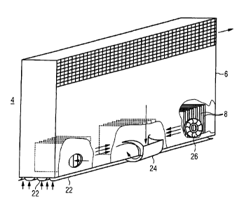
Fig. 3 the recombiner according to Fig. 2 in a side view.
The same parts are provided with the same reference numbers in all
figures.
The security system 1 according to Fig. 1 is provided for the
recombination of hydrogen in a gas mixture, namely in the
containment atmosphere of a safety container 2 of a nuclear plant,
shown in extracts in Fig. 1. To this end, the security system 1
comprises a plurality of catalytic recombiner elements 4 arranged
inside the safety container 2; each of said recombiner elements
catalytically triggering a recombination reaction of hydrogen
carried along in a feed gas flow with oxygen contained in the
containment atmosphere.
For this purpose, each of the thermal recombiner elements 4, as can
CA 02709226 2010-06-14
22
be seen in the enlarged illustration in Fig. 2, comprises a
plurality of catalyst elements 8 arranged in a housing 6. In Fig.
2, for the sake of clarity, four catalyst elements 8 are visible,
however, in the example of the embodiment, in particular ten or
more catalyst elements 8 are arranged in a common housing 6. The
catalyst elements 8 each have a surface provided with a suitably
selected material, for example palladium and/or platinum, said
surface triggering a catalytic recombination reaction with oxygen
contained in the atmospheric gas in an adjacent gas mixture in the
event that this gas mixture contains significant hydrogen
components of e.g. several % by volume. The hydrogen with the
oxygen undergoes an exothermic reaction thereby while forming
water. The catalyst elements 8 for their part are heated by this
exothermic reaction, so that, due to the temperature drop resulting
therefrom, a convection flow from the bottom to the top is produced
in the surrounding gas chamber.
To promote this convection flow by the so-called funnel effect, the
housing 6 of the respective recombiner element 4 surrounding the
catalyst elements 8 is appropriately designed, in particular in a
funnel-like manner, and, to further facilitate the convection flow
resulting therefrom, the catalyst elements 8 are designed
essentially plate-like and arranged parallel to one another.
Furthermore, the recombiner element 4 has an overall height of
about 3 m and a ratio of shaft- depth and shaft height of 1:3 to
1:5. In the inlet area 10 for the gas flow, the recombiner element
4 has, in addition, a portion of freely flowable cross sectional
areas, i.e. not hindered by the fittings, of about 90%. In its
entirety, the recombiner element 4 formed from these components
thus has structural properties which automatically start a
CA 02709226 2010-06-14
23
catalytic recombination process in the presence of hydrogen in the
atmospheric gas of the safety container 2 and maintain it by the
supportive effect of the convection flow due to the funnel effect,
and cause a further mixture of the atmosphere until a sufficient
degradation of the hydrogen has taken place.
The catalyst element 8 has a catalytically active zone 12
consisting of a porous material in each case, in particular of
A1203. The porous material is thereby applied to a suitable thin
metal carrier having an Al component as a ceramic wash coat pore
system and, in addition, with a suitable etch-coat adhesive layer
to attain sufficient abrasion resistance.
This ensures an
enlargement of the inner surface, which promotes the catalytic
effect, by more than the factor 10000. The porous material of the
catalytically active zone 12 is thereby doted with catalytic
material, in particular with Pt and/or Pd, wherein the Pt and/or Pd
distribution is placed largely homogeneously, also into the deeper
lying areas of the pore system, to prevent deactivation by catalyst
poisons or the like.
For an especially advantageous catalytic effect, an overdoting of
up to 25 g/m2 is provided for the noble metal concentration.
The security system 1 is designed in its entirety to ensure a safe
and reliable recombination of the hydrogen produced thereby,
possibly in the atmosphere of the safety container 2, in a
plurality of possible breakdown scenarios, including also
comparatively improbable extreme breakdown conditions. For this
purpose, the security system 1 is designed for the degradation of
hydrogen with the emphasis on catalytic recombination, whereby, if
CA 02709226 2010-06-14
24
necessary, and in particular locally limited, an ignition of an
ignitable gas mixture should also take place. To this end, the
catalytic recombiner elements 4 are predominantly designed, with
respect to type, positioning and dimensioning of their components,
such that no ignition takes place in gas mixtures having a hydrogen
concentration of up to about 6% by volume or, if required, also up
to about 8% by volume, at higher vapor concentrations of up to >10%
by volume, but that the hydrogen degradation takes place on the
surface of the catalyst elements 8 by the catalytically triggered
recombination reaction.
On the other hand, for higher hydrogen concentrations, it is
additionally provided that the catalyst elements 8 are heated by
the thermal energy released by the catalytic recombination reaction
such that their temperature is in the manner of so-called "hot
spots" at predetermined ignition zones 20 provided therefor and
which preferably lie directly in the inlet area of the catalyst,
above the ignition temperature of the gas mixture and thus supports
an ignition of the gas mixture in the manner of a passive system
automatically triggering the recombination process. The individual
components of the system are thereby designed by arrangement,
structure and dimensioning of the fittings within the housing 6, in
particular the catalyst elements 8, taking into consideration the
heat released during the recombination reaction and the dissipation
of heat due to radiant heat or also- in the form of heat conduction
over the individual components of the system such that a surface
temperature is produced in the predetermined ignition zone 20 of
between 600 C and 900 C, i.e. of more than the ignition temperature
of hydrogen of about 560 C, under reference conditions in the
convective operation of the respective recombiner element 4 at
CA 02709226 2010-06-14
25 =
ambient conditions of about 1 bar and 100 C of a hydrogen
concentration in the feed gas flow to the catalyst elements 8 of
more than 5% by volume.
In this design of the recombiner elements 4, the realization is
taken into account that each of the catalyst elements 8, which can
also in part be partially surrounded by metal, are flowed about in
the catalytic recombination operation, i.e. in the presence of
natural convection, by the gas flow requiring treatment, a
depletion of the hydrogen constituent in the gas flow taking place
in direct vicinity of the catalytic surfaces of the catalyst
elements 8 due to the ending recombination reaction. In the state
of the natural convection, the catalyst elements 8 are thus
contacted directly by the depleted gas in the manner of a layered
gas flow, whereby non-depleted gas with a correspondingly increased
hydrogen content is present in further remote spatial areas.
Therefore, in this state of the natural convection, the ignition
effect which the heated catalyst material can exert on the
surrounding gas flow is reduced by the depleted gas layer.
This effect is used in the recombiner element 4 to operate the
predetermined ignition points 20, if necessary, i.e. in particular
in the state of the natural convection, in the manner of an
overcritical modus in which a surface temperature that is actually
above the ignition threshold prevails. In a state of this type,
the system is thus comparatively sensitive to breakdowns or the
flow conditions, where, in the event that the depleted gas layer
which contacts the overheated surface parts is broken open and non-
depleted gas can reach these surface parts, an ignition is
spontaneously triggered due to the increased temperature. Thus,
CA 02709226 2010-06-14
26
with this design of the system, the triggering of an ignition can
be obtained spontaneously and with negligible ignition delay time
when there are pressure pulses or gas displacement processes in
flow conditions in the direct vicinity of the catalyst elements 8.
Thus, in particular an automatic and passive ignition can be
assured in the event that pressure pulses occur inside the safety
container 2, so that a reliable ignition can already be triggered
in the forefield of possibly imminent breakdowns or the like.
To further increase the sensitivity of the system to pressure
pulses or gas displacement processes or the like and thus further
increase the reliability and safety of the ignitions to be
introduced, suitable means for flow focussing can be connected
upstream in individual catalyst elements 8 which promote or
increase the controlled conveyance of incoming pressure pulses or
gas flows to the predetermined ignition zones 20. As can be seen
in the illustration in Fig. 3, baffles 22, diversion plates 24,
whirling or turbulence generators 26 or other suitable means of
confusers are provided for the catalyst elements 8 arranged in the
housing as suitable means for the flow conductance, an incoming
pressure can be guided in a controlled manner to the spatial area
in the vicinity of the predetermined ignition zone.
CA 02709226 2010-06-14
=
=
27
Reference Numbers
1 Security System
2 Safety Container
4 Recombiner Element
6 Housing
8 Catalyst Element
Inlet Area
12 Active Zone
Predetermined Ignition Zone
26 Turbulence Generator
=