Note: Descriptions are shown in the official language in which they were submitted.
CA 02709336 2011-06-21
TENSIONING OF THE TOP ROLL OF A CROP CONDITIONER
This invention relates to a crop conditioner including two generally
parallel rolls forming a nip through which the crop passes with one of the
rollers
being movable to increase the width of the nip, and particularly to a
tensioning
arrangement for applying tension to the movable roller.
BACKGROUND OF THE INVENTION
Hay conditioners generally include a pair of rollers mounted in co-
extensive parallel relationship for rotation about respective axes with the
crop
arranged to pass between the rollers in a conditioning action.
Each of the rollers generally carries a plurality of longitudinally
extending angularly spaced flutes which project outwardly from the surface of
the
roller. The rollers are spaced by a set distance at the nip such that the
flutes
intermesh generally without contact between the rollers. The intermeshing of
the
flutes causes the crop material to be bent as it passes between the rollers
causing a
cracking of the waxy surface of the crop stem.
It is necessary in such rollers to allow one of the rollers, generally the
top roller, to move in a direction to increase the width of the nip by
increasing the
spacing between the axes of the rollers, to accommodate different amounts of
crop
material passing between the rollers and to accommodate obstacles such as
stones
and sticks which pass through without causing damage to the rollers. Generally
this
movement is provided by carrying each end of the top roller on a pivot arm or
pivot
plate which allows pivotal movement about an axis parallel to the axis of the
roller
CA 02709336 2011-06-21
2
together with a spring biasing system which applies tension to the top roller
acting to
close the nip while allowing each end independently to rise and lower in a
floating
action.
US patent 7,188,461 (Fox) assigned to the present assignee and
issued March 13, 2007 discloses an arrangement of this type where the top
roller is
spring biased downwardly into contact with the crop by a pair of springs
operating at
opposite ends of the top roller. Each spring is mounted within a transverse
beam
across the conditioner. The springs extend from an inner end carried on a
bracket
attached to the beam to an outer end which carries a threaded rod which
extends
from the outer end of the spring to the outer end of a pivotal link. Thus the
spring
pulls inwardly holding the structure in the closed position. In the event that
the link is
pivoted outwardly by lifting of the end of the roller, the rod is moved
outwardly thus
tensioning the spring.
US patent 5,022,219 (Knurr) assigned to Gehl and issued June 11,
1991 discloses an arrangement of this type where a conditioner having first
and
second conditioning rolls, one of which is movably mounted, includes a
mounting
system for selectively urging the movable roll toward the other roll. The
mounting
system includes a pair of mounting plates adapted for placement one on either
side
of the movable roll, with the mounting plates being pivotally mounted to a
frame. A
hydraulically operated adjustment arrangement is connected to the mounting
plates
to relieve the biasing force exerted on the mounting plates, thus allowing
movement
CA 02709336 2011-06-21
3
of the movable roll away from the other roll to accommodate passage of a mass
of
material therethrough.
US patent 4,896,483 (O'Halloran) assigned to Hay and Forage and
issued January 30, 1990 discloses a crop conditioner having a frame and first
and
second rolls each rotatable about an axis of rotation. A mounting assembly for
the
first roll includes a sub-assembly at each end of the first roll which permit
the first roll
to be pivoted relative to the second roll. Each sub-assembly has a mounting
plate
rotatably supporting one end of the first roll and supported on the frame for
pivotal
movement about a pivot axis which is generally parallel to. and displaced from
the
axis of rotation of the first roll such that the axis of rotation of the first
roll is movable
relative to the axis of rotation of the second roll between a first position,
a second
position and a third position. The second and third positions of the first
roll are
progressively farther away from the axis of rotation of the second roll than
the first
position. A spring extending generally parallel to the axis of the rolls
exerts a biasing
force on the mounting plate through a cam plate to press the first roll toward
the
second roll. The spring and cam plate are arranged so that the biasing force
has a
magnitude which is less when the first roll is located between the second and
third
positions than when the first roll is located between the first and second
positions.
US patent 4,472,927 (Vogt) assigned to Deere and issued September
25, 1984 discloses a hay conditioner of typical construction which discloses
very
schematically a spring for tensioning the top roll onto the bottom roll
through a bell
crank and a link. The upper roll is free to move upwardly in response to crops
CA 02709336 2011-06-21
4
passing between the rolls, but its downward movement is limited to the stopped
position selected by an adjustment link with the link extending upwardly to a
free end
that is accessible to receive a wrench.
US patent 4,516,392 (McLean) assigned to Sperry New Holland and
issued May 14, 1995 discloses a mower-conditioner having a pair of rotatable
conditioning rolls where the bearings rotatably supporting each conditioning
roll are
recessed into the end of the conditioning roll.
SUMMARY OF THE INVENTION
It is one object of the present invention, therefore, to provide a
tensioning arrangement for applying tension to the movable roller a crop
conditioner.
According to a first aspect of the invention there is provided a
conditioner for conditioning cut crop material from a harvester comprising:
a conditioner frame;
a first roller mounted in the conditioner frame for rotation about an axis
of the first roller with the axis being mounted in fixed position in the
frame;
a second roller mounted in the conditioner frame for rotation about an
axis of the second roller;
a drive input for driving rotation of at least one of the first and second
rollers;
each respective end of the second roller being mounted on a
respective mounting assembly arranged to allow movement of the respective end
of
CA 02709336 2011-06-21
the second roller relative to the first roller in a direction to increase and
decrease
spacing between the axes of the first and second rollers;
each mounting assembly including:
a pivotal mounting member arranged to allow pivotal movement of the
5 respective end of the second roller about a roller pivot axis generally
parallel to the
axis of the second roller and offset to one side thereof;
a tension link extending in a direction lying substantially in a radial
plane of the roller pivot axis and having one end connected to the pivotal
mounting
member so as to apply a force to the pivotal mounting member in a direction to
move the second roller toward the first roller;
a tension spring for applying spring force to the tension link;
a bell crank mounted on the conditioner frame for pivotal movement of
the bell crank, the bell crank having a first end connected to the tension
link and a
second end connected to the spring;
the bell crank having a crank pivot axis which lies transversely to a line
at the bell crank parallel to the pivot axis of the second roller;
the bell crank extending from the first end to the second end in a
direction outwardly of the radial plane of the roller pivot axis;
wherein the tension spring is generally parallel to the tension link and
has its end connected to the second end of the bell crank outward from the
tension
link in a direction away from the radial plane of the roller pivot axis.
CA 02709336 2011-06-21
6
Preferably the crank pivot axis is directly or approximately parallel to
the radial plane of the roller pivot axis, that is approximately at right
angles to the
pivot axis. This is contrary to conventional arrangements in which the axis is
parallel
to the roller axes and provides significant advantages as set out hereinafter.
Preferably the tension link extends generally downwardly from the
pivotal mounting member.
Preferably the tension spring extends generally upwardly from the
second end of the bell crank.
Preferably the tension spring extends from the second end of the bell
crank upwardly to a mounting point at a position on the conditioner frame at
height
above the second roller.
Preferably the mounting point is inward of the second end of the bell
crank.
Preferably there is provided a stop assembly for limiting movement of
the second roller in a direction toward the first roller, the stop assembly
includes an
adjustment link extending to an adjustment point at a top of the conditioner
frame
above the second roller and the mounting point is located on the frame
adjacent the
adjustment point.
Preferably the stop assembly includes a plate with a hole therein
defining a path of movement of the second roller and the adjustment link is
arranged
to move the plate.
CA 02709336 2011-06-21
7
Preferably the conditioner frame includes at each end an end plate in a
radial plane of the axes of the first and second rollers and includes a top
flange at
right angles to the end plate and projecting outwardly therefrom, and the
mounting
point and the adjustment point are connected to the top flange.
Preferably the conditioner frame includes a rear flange at right angles
to the end plate and projecting outwardly therefrom, and a mounting for the
roller
pivot axis and a mounting for the crank pivot axis are located at the rear
flange so
that the' tension link and the tension spring extend upwardly and forwardly
from the
rear flange.
Preferably each roller has a generally cylindrical roller surface and a
plurality of side by side flutes at angularly spaced positions therearound,
the flutes
projecting radially outwardly to a flute edge spaced outwardly of the roller
surface
and extending generally longitudinally along the roller substantially along
the full
length thereof. Alternatively the rollers may be plain with no flutes so that
the
conditioning action occurs by crushing. Plain rollers can be smooth or may
include
small striations or ribs. The rollers are preferably of metal but can be
formed of a
resilient rubber material. The term "nip" used herein is not intended to
require a line
of contact between the roller, but is intended to include rollers where they
approach
but do not touch such as the above fluted rollers which typically condition by
cracking the crop by bending rather than by crushing.
Thus, as described in more detail hereinafter, the roller tension spring
is mounted in a generally vertical configuration. The spring pulls on the bell
crank
CA 02709336 2011-06-21
8
which applies a downward force on the top conditioner roll arm via the tension
link.
The plane of action of the tension mechanism is generally perpendicular to the
plane
of action of the roll mounting mechanism. The tension adjustment of the
downward
pressure on the top conditioner roll can be adjusted easily from the top of
the
header, close to the location of the roll gap adjustment.
The bell crank system allows for better control of down force applied to
the top conditioner roll arm through opening range.
The arrangement which causes the tension mechanism to operate
perpendicular to the roll support mechanism allows for more optimal spatial
design
and an easier adjustment of roll down force.
Key elements therefore which may be obtained in this linkage by the
arrangement described hereinafter are:
1. Control of forces on arm through manipulation of the bell crank.
2. A compact design integral to side of the conditioner.
3. The linkage works in a plane parallel to the rolls so less cross
sectional space is required for the tension mechanism. The tension mechanism
does not interfere as much with the drive mechanism, or the roll opening.
4. Easier adjustment from on top.
According to a second aspect of the invention there is provided a
conditioner for conditioning cut crop material from a harvester comprising:
a conditioner frame;
CA 02709336 2011-06-21
9
a first roller mounted in the conditioner frame for rotation about an axis
of the first roller with the axis being mounted in fixed position in the
frame;
a second roller mounted in the conditioner frame above the first roller
for rotation about an axis of the second roller;
a drive input for driving rotation of at least one of the first and second
rollers;
each respective end of the second roller being mounted on a
respective mounting assembly arranged to allow upward movement of the
respective end of the second roller relative to the first roller to increase
and decrease
spacing between the axes of the first and second rollers;
each mounting assembly including:
a pivotal mounting member arranged to allow said upward
movement of the respective end of the second roller about a roller pivot axis
generally parallel to the axis of the second roller and offset to one side
thereof;
a tension link lying substantially in a radial plane of the roller
pivot axis and having an upper end connected to the pivotal mounting member
and
extending downwardly therefrom so as to apply a downward force to the pivotal
mounting member to move the second roller toward the first roller;
a tension spring for applying spring force to the tension link;
a bell crank mounted on the conditioner frame for pivotal
movement of the bell crank, the bell crank having a first end connected to the
tension link and a second end connected to the spring;
CA 02709336 2011-06-21
wherein the bell crank is located below the first roller and the
tension link extends downwardly from the pivotal mounting member to the bell
crank
and wherein the tension spring extends upwardly from the
second end of the bell crank to a mounting point on the conditioner frame
above the
5 second roller.
According to a third aspect of the invention there is provided a
conditioner for conditioning cut crop material from a harvester comprising:
a conditioner frame;
a first roller mounted in the conditioner frame for rotation about an axis
10 of the first roller with the axis being mounted in fixed position in the
frame;
a second roller mounted in the conditioner frame for rotation about an
axis of the second roller;
a drive input for driving rotation of at least one of the first and second
rollers;
each respective end of the second roller being mounted on a
respective mounting assembly arranged to allow movement of the respective end
of
the second roller relative to the first roller in a direction to increase and
decrease
spacing between the axes of the first and second rollers;
each mounting assembly including:
a pivotal mounting member arranged to allow movement of the
respective end of the second roller about a roller pivot axis generally
parallel to the
axis of the second roller and offset to one side thereof;
CA 02709336 2011-06-21
11
a tension link lying substantially in a radial plane of the roller
pivot axis and having one end connected to the pivotal mounting member and
extending therefrom in a direction so as to apply a force to the pivotal
mounting
member to move the second roller toward the first roller;
a tension spring for applying spring force to the tension link;
a bell crank mounted on the conditioner frame for pivotal
movement of the bell crank, the bell crank having a first end connected to the
tension link and a second end connected to the spring;
wherein the tension spring extends from the second end of the
bell crank to a mounting point on the conditioner frame with the tension
spring
including an adjustment mechanism at the mounting point;
wherein there is provided a stop assembly for limiting movement
of the second roller in a direction toward the first roller;
wherein the stop assembly includes an adjustment link
extending to an adjustment point on the conditioner frame;
and wherein the mounting point of the tension spring is located
on the conditioner frame adjacent the adjustment point of the adjustment link.
BRIEF DESCRIPTION OF THE DRAWINGS
One embodiment of the invention will now be described in conjunction
with the accompanying drawings in which:
Figure 1 is an isometric view of one embodiment of a conditioner
CA 02709336 2011-06-21
12
according to the present invention.
Figure 2 is an isometric view on an enlarged scale of the conditioner of
Figure 1 showing the drive end.
Figure 3 is an isometric view on an enlarged scale of the conditioner of
Figure 1 showing the non-drive end.
Figure 4 is an end elevational view of the conditioner of Figure 1 at the
non drive end of Figure 3.
In the drawings like characters of reference indicate corresponding
parts in the different figures.
DETAILED DESCRIPTION
A conditioner 10 for conditioning cut crop material from a harvester is
shown in the figures and is arranged to be mounted behind the cutter bar of a
harvesting machine with a discharge opening of the machine.
Examples of machines of this type are disclosed in the following
documents of the present Assignees.
US patent 7,340,876 issued March 11, 2008 which corresponds to US
Published Application 2008/0066440 filed September 15'', 2006 and published
March 23, 2008 and to Canadian application 2,559,353 discloses an arrangement
which provides impellers of an hour glass shape arranged at the outer cutter
disks.
The disclosure of this document can be referred to for further detail of the
impellers.
US patent 7,454,888 issued November 25, 2008 which corresponds to
US Published Application 2008/0066441 filed September 15th, 2006 and published
CA 02709336 2011-06-21
13
March 23, 2008 and to Canadian application 2,559,217 discloses an arrangement
which provides a transfer roller between the cutter disks and the conditioning
rollers
where the transfer roller is of the same diameter as the bottom roll and
carries high
ribs preferably forwardly inclined for an aggressive action on the crop. The
roller is
mounted with its axis above the cutting plane and its uppermost edge of the
ribs at
or above the axis of the bottom roll. The disclosure of this document can be
referred
to for further detail of the transfer roll.
US patent 7,356,982 issued April 15, 2008 which corresponds to US
Published Application 2008/0066439 filed February 15th, 2007 and published
March
23, 2008 and to Canadian application 2,578,907 discloses another arrangement
which provides impellers of an hour glass shape arranged at the outer cutter
disks.
The disclosure of this document can be referred to for further detail of the
impellers.
US Published Application 2009/0071116 filed July 23, 2008 and
published March 23, 2009 which corresponds to Canadian application 2,639,032
discloses an arrangement where a swath converging apparatus is mounted in the
mouth of the opening and is formed by two pairs of upstanding cylindrical
rollers
rotatable about their axes in a direction to carry the crop inwardly of the
discharge
opening. The pairs are mounted on respective top and bottom plates which pivot
about the axis of the outer roller with the latter extending forwardly to
overlap a floor
plate of the cutter bar. The disclosure of this document can be referred to
for further
detail of the converging apparatus.
CA 02709336 2011-06-21
14
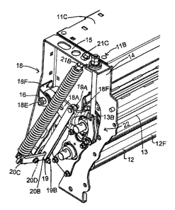
The conditioner 10 includes a conditioner frame 11 defined by end
frame elements 11A and 11 B together with suitable transverse connecting
elements
11 C. The frame supports a pair of rollers 12 and 13 each mounted for rotation
about
a respective longitudinal axis 12A, 13A.
Each end frame element includes a main upstanding plate 14 at right
angles to the axes 12A, 13A at the ends of the rollers together with a rear
flange 16
at a rear edge of the plate 14 and a top flange 15 at a top edge of the plate
with the
flanges extending outwardly from the main plate.
The conditioner rollers 12, 13 are of the fluted intermeshing type with
flutes 12F arranged along the roller in helical manner and formed from a bar
or angle
welded onto the outer surface of the roller.
The first or bottom roller 12 is mounted in the conditioner frame for
rotation about the axis 12A of the first roller with the axis 12A being
mounted in fixed
position in the frame. The roller is carries in bearings 12B carried on a
bearing
mounting plate 12C attached to the end plate 14 at a fixed position thereon.
Thus
the plate 14 has a bottom slot 14A extending upwardly and forwardly from the
bottom of the rear flange 16 into which the bearing slides with the plate 12C
being
attached to the plate 14 on either side of the slot by bolts 12D.
The second or top roller 13 is mounted in the conditioner frame for
rotation about the axis 13A of the second roller. Each respective end of the
second
roller 13 is mounted on a respective mounting assembly 18 arranged to allow up
and
down movement of the respective end of the top roller relative to the bottom
roller in
CA 02709336 2011-06-21
a direction to increase and decrease spacing between the axes 12A and 13A of
the
rollers.
The roller 13 is carried in bearings 13B which are mounted on a pivotal
mounting member 18A arranged to allow pivotal movement of the end of the top
5 roller about a roller pivot axis 18B generally parallel to the axis 13A of
the second
roller and offset to one side thereof. The mounting member 18A comprises a
formed
plate 18P with a sleeve 18C at one end which contains a bearing 18D mounted on
a
pin 18E carried on a bracket 18F bolted to the rear flange 16. The plate 18P
is thus
carried on the end plate 14 parallel to the plate 14 but spaced outwardly from
that
10 plate. A bifurcated support portion 18F is formed integrally with the plate
18P and
extends toward the plate 14 where it supports the bearingsl 3B.
A tension link 19 is connected to the plate 18F at a pin 19A and
extends downwardly therefrom to a bell crank 20 to which is attached by a pin
19B.
The link 19 extends in a direction lying substantially in a radial plane of
the roller
15 pivot axis 12A and has its upper end connected to the pivotal mounting
plate 18P so
as to apply a force to the pivotal mounting member 18A downwardly, that is, in
a
direction to move the top roller downwardly toward the bottom roller.
The bell crank 20 is connected to a tension spring 21 for applying
spring force to the tension link. The bell crank 20 is mounted on the
conditioner
frame by a bushing 21A for pivotal movement of the bell crank. The bushing 21A
is
mounted at the bottom of the rear flange 16. The bell crank 20 has a first end
20B
CA 02709336 2011-06-21
16
connected to the tension link at the pin 19B and a second end 20C connected to
the
spring at a bottom connection 21A.
The bell crank having a crank pivot axis 20D defined by the bushing
20A which lies transversely to a line L at the bell crank parallel to the
pivot axis of
the second roller, that is, the bell crank extends from the first end at the
pin 19B to
the second end at the connection 21A in a direction outwardly of the radial
plane of
the roller pivot axis.
This is contrary to the conventional arrangement in which a bell crank
lies in a radial plane of the roller axis with its pivot axis parallel to the
roller axis. In
the arrangement shown, the crank pivot axis 20D is directly parallel, at 0
degrees, to
the radial plane of the roller pivot axis. However this angle is not
necessarily zero
and there may be some twisting of the various components to provide an
improved
geometry which mean that this is not necessarily so.
The spring 21 extends from its connection 21A to the bell crank at the
lower end upwardly and forwardly to an upper end 21 B where it is connected to
the
top flange 15 by an adjustment screw 21 C. Thus tension generated by the
tension
spring is applied through the bell crank to the tension link acting to pull
downwardly
on the roller 13.
The tension link 19 extends generally downwardly from the pivotal
mounting member IBA and the tension spring 21 extends generally upwardly from
the second end of the bell crank to the top flange 15.
CA 02709336 2011-06-21
17
The tension spring 21 is generally parallel to the tension link 19 and
has its lower end 21A outward from the lower end of the tension link 19 in a
direction
away from or outwardly from the radial plane of the roller pivot axis at the
bearings
13B. The mounting point 21 B is inward of the connection 21A at the outer end
of the
bell crank so that the spring is inclined upwardly and inwardly.
A stop assembly 22 is provided for limiting movement of the top roller
13 downwardly toward the bottom roller 12. The stop assembly includes an
adjustment link 22A extending to a screw 22C at an adjustment point 22B at the
top
flange 15 of the conditioner frame above the top roller. Thus the top end 21 B
of the
spring and its mounting point at the adjustment nut 21C is located on the
frame
adjacent the adjustment point 22B. In this way both adjustments are readily
available at the top flange 15 for adjustment from above the flange.
The stop assembly 22 includes a plate 22B with a hole 22C therein
defining a path of movement of the top roller 13. The adjustment link 22A when
adjusted by the screw 22C is arranged to move the plate upwardly and
downwardly
to locate the bottom of the hole 22C which locates the lowest point of
movement of
the roller 13 which is allowed by the plate 22B.
A drive system 30 is provided and shown only schematically since this
can be of any suitable arrangement for driving the rollers 12 and 13.
Since various modifications can be made in my invention as herein
above described, and many apparently widely different embodiments of same made
within the spirit and scope of the claims without department from such spirit
and
CA 02709336 2011-06-21
18
scope, it is intended that all matter contained in the accompanying
specification shall
be interpreted as illustrative only and not in a limiting sense.