Language selection

Search

Patent 2709565 Summary

Third-party information liability

Some of the information on this Web page has been provided by external sources. The Government of Canada is not responsible for the accuracy, reliability or currency of the information supplied by external sources. Users wishing to rely upon this information should consult directly with the source of the information. Content provided by external sources is not subject to official languages, privacy and accessibility requirements.

Claims and Abstract availability

Any discrepancies in the text and image of the Claims and Abstract are due to differing posting times. Text of the Claims and Abstract are posted:

  • At the time the application is open to public inspection;
  • At the time of issue of the patent (grant).
(12) Patent Application: (11) CA 2709565
(54) English Title: DC POWER TOOL WITH SAFETY DETECTION DEVICE
(54) French Title: OUTIL A COURANT CONTINU AVEC DISPOSITIF DE DETECTION POUR SECURITE
Status: Dead
Bibliographic Data
(51) International Patent Classification (IPC):
  • B25F 5/00 (2006.01)
  • H02H 3/20 (2006.01)
  • H02H 5/04 (2006.01)
  • H02H 7/00 (2006.01)
  • H02J 7/00 (2006.01)
(72) Inventors :
  • YANG, DEZHONG (China)
  • DUAN, JUNYA (China)
(73) Owners :
  • CHERVON LIMITED (China)
(71) Applicants :
  • CHERVON LIMITED (China)
(74) Agent: NORTON ROSE FULBRIGHT CANADA LLP/S.E.N.C.R.L., S.R.L.
(74) Associate agent:
(45) Issued:
(22) Filed Date: 2010-07-15
(41) Open to Public Inspection: 2011-01-17
Examination requested: 2010-10-04
Availability of licence: N/A
(25) Language of filing: English

Patent Cooperation Treaty (PCT): No

(30) Application Priority Data:
Application No. Country/Territory Date
200920233242.X China 2009-07-17

Abstracts

English Abstract


A DC power tool having an interiorly provided lithium battery element and a
charging switch includes a safety protection module to eliminate the risk of
circuitry burn-out
and other dangers resulting from connecting the power tool to a power supply
with
unmatched rated voltage and rated current when charging the power tool via use
of an
adapter.


Claims

Note: Claims are shown in the official language in which they were submitted.


CLAIMS

What is claimed is:


1. A DC power tool having an interiorly provided lithium battery element and a
charging
switch connectable to an exterior power supply wherein the DC power tool
further comprises
a safety protection module.


2. The DC power tool of Claim 1, wherein the safety protection module is an
over-current
and over-voltage protection module.


3. The DC power tool of Claim 2, wherein the over-current and over-voltage
protection
module comprises a locking device.


4. The DC power tool of Claim 1, wherein the safety protection module is an
over-current
protection module.


5. The DC power tool of Claim 1, wherein the safety protection module is an
over- voltage
protection module.


6. The DC power tool of Claim 1, wherein the safety protection module is an
overheating
protection module.


4


7. A DC power tool having an interiorly provided battery element and a
charging switch for
controlling a charging process and an outer adapter connectable to a power
supply in the
charging process wherein the DC power tool further comprises a safety
protection module
electrically connected to the charging circuit for providing safety protection
and wherein the
safety protection module comprises:

a current sampling circuit connected to the battery element to detect a
current
provided to the charging circuit, and

a current reference circuit to provide a predetermined current value;

wherein an over-current signal is generated when the charge provided to the
charging
circuit is detected as being larger than the predetermined value to turn off
said charging
switch.


8. The DC power tool of Claim 7, wherein the safety protection module further
includes a
voltage reference circuit to provide a predetermined voltage value and to
generate an
over-voltage signal to turn off the charging switch when a voltage value
provided to the
charging circuit larger than the predetermined voltage value is detected.


9. The DC power tool of Claim 8, wherein the over-current signal and over-
voltage signal
are transferred to turn off the charging switch via an OR-gate.


10. The DC power tool of Claim 9, wherein the safety protection module further
includes a
locking device to lock an output of the OR-gate.


11. The DC power tool of Claim 7, wherein the safety protection module further
includes
an overheating protection module for generating an overheating signal when a
temperature
value in the charging circuit higher than a predetermined temperature value is
detected to
turn off the charging switch.


12. The DC power tool of Claim 8, wherein the safety protection module further
includes
an overheating protection module for generating an overheating signal when a
temperature
value in the charging circuit higher than a predetermined temperature value is
detected to
turn off the charging switch.


13. The DC power tool of Claim 9, wherein the safety protection module further
includes
an overheating protection module for generating an overheating signal when a
temperature
value in the charging circuit higher than a predetermined temperature value is
detected to
turn off the charging switch.


14. The DC power tool of Claim 10, wherein the safety protection module
further includes

6


an overheating protection module for generating an overheating signal when a
temperature
value in the charging circuit higher than a predetermined temperature value is
detected to
turn off the charging switch.


7

Description

Note: Descriptions are shown in the official language in which they were submitted.


CA 02709565 2010-07-15

DC POWER TOOL WITH A SAFETY DETECTION DEVICE
BACKGROUND
The subject disclosure relates to DC power tools and, more particularly, to a
DC

power tool which has a built-in lithium battery device and a safety detection
device.

A built-in lithium battery device is widely used in power tools. The built-in
lithium
battery device is generally provided with a charging module and is connected
with a power
supply via an outer power adapter for charging the built-in lithium battery.
While power
adapters generally have a uniform standard interface, the rated voltage and
the rated current

of power supplies connectable to power adapters with the same interface may be
different.
Therefore, when a user charges the built-in lithium battery device, they may
use an
inappropriate power supply which may causes the built-in lithium battery
device to rupture or
even explode in severe case.

SUMMARY
The following describes a DC power tool with a safety detection device for
avoiding
a risk that may result from erroneous connection with a power supply. More
particularly,
the DC power tool is interiorly provided with a lithium battery element and a
charging switch.
The power tool can be connected with a power supply via use of an outer power
adapter and
is further provided with a safety protection module. The safety protection
module is an

over-current and over-voltage protection module and the over-current and over-
voltage
protection module comprises a locking device. In this manner, the power tool
eliminates


CA 02709565 2010-07-15

the risk of circuit damage and other dangers resulting from wrongly connecting
the power
tool to a power supply with unmatched rated voltage and rated current when
seeking to
charge the lithium battery element.

BRIEF DESCRIPTION OF THE DRAWINGS

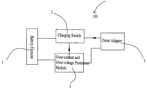
Fig. 1 is an illustrative diagram of an exemplary charging circuit module of a
power
tool constructed according to the description that follows; and

Fig. 2 is an illustrative diagram of an exemplary over-current and over-
voltage
protection module of the charging circuit of Fig. 1.

DETAILED DESCRIPTION

Referring to Fig. 1, a charging circuit module 100 of a DC power tool
comprises at
least one built-in lithium battery element 1, a charging switch 2, and an
outer adapter 4
connected to the charging switch 2. The charging circuit module 100 further
comprises a
safety protection module connected to the charging switch 2 and the adapter 4.
In the
present embodiment, the safety protection module is an over-current and over-
voltage

protection module 3. The adapter 4 can charge the power tool when connected to
an outer
power supply with the charging switch 2 on.

Referring to Fig. 2, the over-current and over-voltage protection module 3 of
the
present embodiment comprises a current reference 31, and the protection module
3 contains a
current sampling circuit 32. The value of the current reference 31 can be
predetermined so
that when the charging current is larger than the predetermined value, the
voltage of the

sampling circuit 32 is increased, and the voltage of the sampling circuit 32
and the reference
2


CA 02709565 2010-07-15

voltage are superposed to form an over-current signal 33. The protection
module 3 can
contain a voltage reference 34. The value of the voltage reference 34 can be
predetermined
so that, when the voltage of the adapter 4 is larger than the predetermined
value, an
over-voltage signal 35 is generated. After the over-current or over-voltage
signal is output

via an OR gate 37, a locking device 36 locks the output and a protection
signal 38 controls
the charging switch 2 to interrupt the charging circuit to stop charging. The
locking is
released when the adapter 4 is removed. In this way, the described system
eliminates the
risk of causing damage to the circuit and other dangers resulting from wrongly
connecting
the adapter with a power supply having unmatched rated voltage and rated
current.

While the foregoing describes a preferred embodiment, it will be understood
that the
safety protection module may only comprise an over-current protection device
or an
over-voltage protection device. Indeed, the safety protection module may
comprise an
overheating protection module to satisfy specific requirements. It will
therefore be further
appreciated that present invention is not intended to be limited to the
embodiment disclosed

in the description and the drawings and that other embodiments are also
feasible. As such,
it is to be understood that other alternations which are apparent to the
person skilled in the art
should be regarded as falling into the protection scope of the claims that
follow.

3
Representative Drawing
A single figure which represents the drawing illustrating the invention.
Administrative Status

For a clearer understanding of the status of the application/patent presented on this page, the site Disclaimer , as well as the definitions for Patent , Administrative Status , Maintenance Fee  and Payment History  should be consulted.

Administrative Status

Title Date
Forecasted Issue Date Unavailable
(22) Filed 2010-07-15
Examination Requested 2010-10-04
(41) Open to Public Inspection 2011-01-17
Dead Application 2014-03-13

Abandonment History

Abandonment Date Reason Reinstatement Date
2013-03-13 R30(2) - Failure to Respond
2013-07-15 FAILURE TO PAY APPLICATION MAINTENANCE FEE

Payment History

Fee Type Anniversary Year Due Date Amount Paid Paid Date
Registration of a document - section 124 $100.00 2010-07-15
Application Fee $400.00 2010-07-15
Request for Examination $800.00 2010-10-04
Maintenance Fee - Application - New Act 2 2012-07-16 $100.00 2012-06-22
Owners on Record

Note: Records showing the ownership history in alphabetical order.

Current Owners on Record
CHERVON LIMITED
Past Owners on Record
DUAN, JUNYA
YANG, DEZHONG
Past Owners that do not appear in the "Owners on Record" listing will appear in other documentation within the application.
Documents

To view selected files, please enter reCAPTCHA code :


To view images, click a link in the Document Description column. To download the documents, select one or more checkboxes in the first column and then click the "Download Selected in PDF format (Zip Archive)" or the "Download Selected as Single PDF" button.

List of published and non-published patent-specific documents on the CPD .

If you have any difficulty accessing content, you can call the Client Service Centre at 1-866-997-1936 or send them an e-mail at CIPO Client Service Centre.


Document
Description 
Date
(yyyy-mm-dd) 
Number of pages   Size of Image (KB) 
Abstract 2010-07-15 1 9
Description 2010-07-15 3 106
Claims 2010-07-15 4 80
Drawings 2010-07-15 1 12
Cover Page 2011-01-07 1 30
Representative Drawing 2010-12-22 1 5
Correspondence 2010-08-18 1 14
Assignment 2010-07-15 8 296
Prosecution-Amendment 2010-10-04 2 73
Prosecution-Amendment 2012-09-13 2 84