Note: Descriptions are shown in the official language in which they were submitted.
CA 02710563 2013-07-23
HEIGHT ADJUSTABLE AND REMOVEABLE CONTAINER SYSTEM
BACKGROUND OF THE INVENTION
Mounting decorative and functional receptacles to and suspending them from
overhead surfaces
is a popular and attractive way of displaying planters, bird feeders, lamps,
and similar container based
items. Whether mounted and hung from an indoor ceiling or outdoors from a roof
overhang or a tree,
suspended planters, birdfccders and similar hanging devices provide an
appealing and convenient
alternative to ground base support of such items.
However, suspended containers present the obvious problem of being out of
reach to the normal
user who must gain access to the container, e.g. to water or attend to a plant
in a suspended planter, to till
a suspended birdfeeder, or maintain a lamp. The use of a step stool to reach
elevated containers, while
functional, presents the normal hazards which are inherent with standing on a
ladder. Moreover, when
step stools are not available, the user may attempt to reach the container by
alternate, unsafe means. Thus,
the removal of a container to attend to its contents and then the replacement
of the container in its
elevated position is an inconvenient, time consuming, and potentially unsafe
process.
The problems associated with suspended, container based items have been
recognized by the
prior art. For example, U.S. Pat Nos. 4,187,996, 5,052,148, and 5,065,971
disclose various height
adjustable planter systems. However, these and similar systems either operate
by means of an inordinate
number of moving parts which are susceptible to breakage, are expensive to
manufacture, and therefore
impractical, or they are unstable and difficult to precisely position. Most
are cumbersome to operate as
well.
The limitations and disadvantages of existing, suspended containers are
largely addressed in US
Patent 8,047,495, which discloses a unique, effective, and efficient height
adjustable container system.
However, that system does not relate to removal of the
CA 02710563 2010-07-20
container from the suspended system, to setting the container at a variety of
heights on the
system, and other important functions.
SUMMARY OF THE INVENTION
It is thus the object of the present invention to provide a height adjustable
and
removeable container system which not only overcomes the limitations and
disadvantages of
prior container suspension systems, but also provides for additional
versatility to the system
disclosed in the above referenced application.
It is the object of the present invention to provide a height adjustable and
removeable
container system which provides quick and easy access to a suspended planter,
bird feeder, lamp
component or similar container-based item.
It is another object of the present invention to provide a height adjustable
and removeable
container system which has a rigid suspended support element for maintaining
the container
precisely in the desired stationary elevated and lowered positions.
It is a further object of the present invention to provide a height adjustable
and
removeable container system which allows the suspended container of this
system to be raised
and lowered with minimal effort.
It is still another object of the present invention to provide a height
adjustable and
removeable container system which allows the suspended container of this
system to be lowered
simply by pushing a button on the inner supporting member on which the
container is suspended,
thus allowing the user to lower the container.
It is another object of the present invention to provide a height adjustable
and removeable
container system which allows the suspended container of this system to be
raised simply by
pushing the container up along its inner supporting member.
2
{2262.00015APF8906)
CA 02710563 2010-07-20
It is a further object of the present invention to provide a height adjustable
and
removeable container system whose up and down operation constitutes a safe and
efficient
means of vertically raising and lowering the container.
It is still another object of the present invention to provide a height
adjustable and
removeable container system which allows the suspended container to be
positioned at
intermediate heights of the system.
It is a further object of the present invention to provide a height adjustable
and
removeable container system which allows the suspended container to be removed
and separated
from the system.
It is another object of the present invention to provide a height adjustable
and removeable
container system which allows the suspended container to be easily rotated
while being
suspended.
It is still another object of the present invention to provide a height
adjustable and
removeable container system which is easy and enjoyable to operate.
It is a further object of the present invention to provide a height adjustable
and
removeable container system which is simply and attractively mountable to an
overhead surface
to maintain the container in a relative immoveable vertical position.
These and other objects are accomplished by the present invention, a height
adjustable
and removeable container system which comprises a container having a center
opening through
which at least one elongated, supporting guide member extends. The container
moves up and
down the guide member and is adjustable to fully raised and fully lowered
positions and can also
be positioned on intermediate heights on the guide member. A handle is
removeably connected
to the end of the guide member to assist in the movement of the container
along the guide
member. The handle can be disconnected and separated from the guide member to
allow the
3
{2262.00015:APF8906)
CA 02710563 2010-07-20
'= ,
container to be removed from the system. A stop pin, stored in the handle when
not in use, is
provided to set the container at intermediate heights on the guide member.
The novel features which are considered as characteristic of the invention are
set forth in
particular in the appended claims. The invention, itself, however, both as to
its design,
construction and use, together with additional features and advantages
thereof, are best
understood upon review of the following detailed description with reference to
the
accompanying drawings.
BRIEF DESCRIPTION OF THE DRAWINGS
FIG. 1. is an elevation view of the height adjustable and removable container
system of
the present invention with its container in the fully raised position.
FIG. 2 is an elevation view of the height adjustable and removable container
system of
the present invention with its container in the fully lowered position.
FIG. 3 is a partial cross-sectional view of the height adjustable and
removable container
system of the present invention depicting the position of the control handle
while supporting the
container.
FIG. 4 is a partially exploded elevation view of the components of the height
adjustable
and removable container system of the present invention.
FIG. 5 is an isometric view of the control handle of the height adjustable and
removable
container system of the present invention with stop pin.
FIG. 6 is an isometric end view of components of the height adjustable and
removable
container system of the present invention.
FIG. 7 is a rear end view of the height adjustable and removable container
system of the
present invention depicting the operation of its keyway system.
FIG. 8 is an end view similar to FIG. 7, depicting the keyway system in locked
position.
4
{2262.00015.APF8906}
CA 02710563 2010-07-20
DETAILED DESCRIPTION OF THE INVENTION
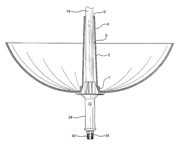
FIGs. 1 and 2 show height adjustable and removal container system 2 with its
container 4
in the fully raised (FIG. 1) and fully lowered (FIG. 2) positions. Container 4
in this embodiment
is bunt-shaped, with upstanding central tubular element 6 and center through
opening 8 (FIG. 3).
The shape and type of container is not to be considered so restrictive, as
many different
containers can be used for the various uses contemplated for the invention,
e.g. for planters, bird
feeders, lighting components, etc.
Outer supporting guide member 14 is positioned within tubular element 6 and
center
opening 8 of container 4. Stop element 16 extends into the interior of outer
member 14. Stop
element 16 can take the form of a screw, bolt, key, or similar structure.
Inner supporting guide
member 18 is positioned within outer member 14. Inner member 18 comprises
elongated slot or
channel 20. Inner member 18 is positioned within outer member 14 such that
stop element 16 is
slideable disposed within slot or channel 20. In this manner, outer member 14
is vertically
slideable over inner member 18 from a retracted position, wherein container 4
is in its fully
raised position (FIG. 1), to an expanded position wherein the container is in
its fully lowered
position (FIG. 2). The design and operation of this system is described
further in co-pending
application S.N. 12/381,346, the subject matter of which is incorporated
herein.
Control handle 24 serves to support container 4 in both its fully raised
position (FIG. 1)
and fully lowered position (FIG. 2). As best seen in FIG. 5, handle 24
comprises a unitary body
26 with through channel 28. Through hole 30 in unitary body 26 is aligned to
receive push
button 32 when container 4 is in its fully raised position. Button 32 is
normally biased outward
by an internal spring located within inner member 18, as more fully described
in co-pending
application S.N. 12/381,346. When button 32 is pressed, both handle 24 and
container 4, which
(2262.00015:APF8906)
CA 02710563 2010-07-20
..=
=
is being supported by the handle, are free to slid down inner member 18 to the
lowered position
shown in FIG. 2.
Handle 24 is normally positioned over the lower end section 15 of outer member
14, this
lower end of outer member 14 being configured to be positioned within through
channel 28 of
handle 24. The distal end of lower end section 15 of outer member 14 has
threads 34. Handle 24
is positioned over lower end section 15 of outer member 14 and slid up over
threads 34. It is
then secured over lower end section 15 by threaded pommel 36 (FIG. 6).
It is important that handle 24 be aligned properly on outer member 14, in
order to ensure
that its through hole 30 can receive button 32 when the handle and container
are slid to their fully
raised position. This is accomplished by the presence of key 38 located at
lower section 27 of
handle 24. A corresponding keyway 40 is located through threads 34 at the
distal end of lower
end section 15 of outer member 14. As shown in FIGS. 6-8, when handle 24 is
slid onto lower
end section 15, it is simply rotated until key 38 enters keyway 40. This locks
handle 24 in
properly aligned position on outer member 14. Pommel 36 can then be screwed
onto threads 34
to secure handle 24 in position on outer member 14.
As best shown in FIG. 5, handle 24 further comprises upper section 41 having
spline
members 42, 43, and 44, which are tapered from the top of the handle to
support platform 25.
Pin socket receptacles 45, 46, and 47 are located on support platform 25 as
well. The socket
receptacles are configured to store stop pin 50 when the pin is not in use.
Stop pin 50 permits container 4 to be adjusted to various heights between its
fully raised
and lowered positions. From the fully lowered position shown in FIG. 2,
container 4 can be slid
off handle 24 and up outer member 14, until it is just above opening 52 which
extends through
the outer member. Stop pin is simply removed from one of the socket
receptacles, e.g. receptacle
45, and inserted through opening 52, thereby maintaining container 4 on outer
member 14 at the
6
(2262.00015:APF8906)
CA 02710563 2010-07-20
=
height of the opening (FIG. 4). It is contemplated that several through
openings at different
heights along outer member 14 can be provided in order to allow the user the
option of
positioning container 4 at these different heights.
The use of stop pin 50 through outer member 14 also allows easy and safe
removal and
separation of container 4 from the outer member. When it is desired to remove
container 4, for
instance when the container is a planter and it is necessary to maintain or
water its plants in
another location, the container is first slid up outer member 14 and retained
in that raised
position by stop pin 50 through opening 52, as previously described and shown
in FIG. 4.
Pommel 36 is unscrewed from threads 34 on outer member 14. Handle 24 is then
slid off the
outer member. Stop pin 50 is removed from opening 52. Container 4 is now free
to slide down
and off outer member 14. The reverse process is employed when container 4
subsequently is to
be reinstalled to the system. It is slid up outer member 14 and retained by
stop pin 50 through
opening 52. Handle 24 is then resecured by pommel 36 to lower end section 15
of outer
member 14 and stop pin 50 is removed from opening 52 and returned to one of
the pin socket
receptacles, e.g. receptacle 45. Now container 4 can be slid down the outer
member to again rest
on support platform 25 of the handle.
Smooth insertion and stability of handle 24 into center opening 8 of container
4 is
accomplished by the tapered nature of wall 5 at the bottom of the container.
As seen in FIG. 3,
wall 5 is wider at its very bottom 7 than at its top 9. Spline Members 42, 43,
and 44 of handle 24
are correspondingly tapered to allow ready interaction between the handle and
container 4, as the
container is slid down over the spline members. Tapered walls 5 also serve to
rotate handle
portion 51 of stop member 50 inward, flush against the surface of outer member
14, when the
stop member is stored within one of receptacles 45, 46, and 47 and container 4
is being slid over
handle 24.
7
(2262.00015:APF8906)
CA 02710563 2010-07-20
Thus the height adjustable and removal container system of the present
invention allows
for increased versatility in such systems. Containers employed with the
present system can be
adjusted to fully raised and fully lowered positions and can also be retained
at intermediate
positions, as desired by the user. The system of the present invention also
permits quick, easy,
and safe removal and reinstallation of the container of the system. When used
as a planter, the
system permits container 4 to be readily rotated about outer member 14, so
that all sides of
flowers and other plants in the container can receive equal sunlight.
Certain novel features and components of this invention are disclosed in
detail in order to
make the invention clear in at least one form thereof. However, it is to be
clearly understood that
the invention as disclosed is not necessarily limited to the exact form and
details as disclosed,
since it is apparent that various modifications and changes may be made
without departing from
the spirit of the invention.
8
{2262.00015 APF8906)