Note: Descriptions are shown in the official language in which they were submitted.
CA 02711020 2013-09-18
TITLE
[0001] METHOD AND CIRCUIT ARRANGEMENT FOR CONNECTING AT
LEAST ONE STRING OF A PHOTOVOLTAIC SYSTEM TO AN INVERTER
FIELD OF THE INVENTION
[0002] The invention relates to a system and method for connecting at least
one
string of a photovoltaic system that contains multiple solar modules to an
inverter that
supplies electrical power from the photovoltaic system to an AC power grid.
BACKGROUND
[0003] A high-performance photovoltaic system usually comprises multiple
strings that contain multiple solar modules each. In such a system, the solar
modules of
each string are connected to each other either in series or in parallel to
ensure that the
desired output voltage and the desired output current are present at each
string. To
connect multiple strings of this type of photovoltaic system to a central
inverter that
supplies electrical power from the photovoltaic system to an AC power grid, it
is often
the case that long power cables have to be installed whose length is
determined by the
surface area of each string as well as the spatial arrangement of all the
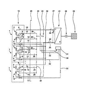
strings. These
power cables are a significant cost factor given their large cross-sections
and moreover
suffer from continuous power loss due to the electrical resistance they cause.
In
general, it would be possible to reduce the requisite cross-section of the
power cables
and the amount of power loss if the output voltage of each string is increased
through
the serial connection of more solar modules while the same number of solar
modules
with less parallel connections would reduce the power accordingly. However,
this
1
CA 02711020 2010-08-06
SMAP105US
09-026 P US
concept cannot be implemented in all cases as it would cause the output
voltages of the
strings to rise to dangerous levels. In the USA, for example, voltages
exceeding 600 V
to ground are generally prohibited in conventional electrical systems. In
practice, this
limits not only the output voltages of the strings in a photovoltaic system
but also the
possibility of conducting smaller currents at higher voltages so as to
minimize the cross-
section of the power cables.
[0004] Known system features implemented in the "Solaron Remote PV Tie
(RPT)"
by Advanced Energy Industries, Inc., Fort Collins, Colorado, USA (see
www.advanced-
energy.com). Based on these features, a string of a photovoltaic system with
multiple
solar modules connected in series and parallel is split into two serially
connected
substrings with a safety switch installed between them. On the output side,
two power
cables with a power switch installed in each are used to connect the string to
an inverter
that supplies electrical power from the photovoltaic system to a three-phase
480 V AC
power grid. While the photovoltaic system is operating, the AC power grid also
provides
a ground reference point for the system. If the photovoltaic system is
disconnected from
the inverter and thus the AC power grid when the power switch in the power
cables
opens, the safety switch between the two substrings opens and the switches in
the
potential cables connecting the substrings to the inverter on both sides of
the safety
switch close. Disconnecting both substrings limits the maximum voltage
generated at
each point of the photovoltaic system and thus the maximum voltage to ground
to 600
volts. Via the potential cable, the two substrings can also be checked for the
presence
of ground faults, provided, of course, the photovoltaic system is switched
off. If the
photovoltaic system is switched on again, the switches in the potential cables
to the
substrings reopen at the same time the safety switch between the substrings
closes to
interrupt the contact provided by the potential cables between the substrings
and the
ground due to the potential reference point of the photovoltaic system via the
480 V AC
power grid. Based on this known circuit arrangement, any ground fault that
occurs while
the photovoltaic system is operating gives rise to major short-circuit
currents that must
be interrupted by triggering a common line circuit breaker or residual current
breaker.
Moreover, while operating the photovoltaic system with the known circuit
arrangement,
the accumulation of voltages greater than 600 V to ground normally cannot be
prevented. One advantage, however, is that only two power cables are needed to
2
CA 02711020 2010-08-06
SMAP105US
09-026 P US
connect the string that supplies an output voltage of 1200 V to the inverter.
All other
cables between the inverter and the strings are not used to conduct power and
can
therefore have a comparatively small cross-section.
SUMMARY
[0005] The invention includes a method and a circuit arrangement for
connecting at
least one string of a photovoltaic system that contains multiple solar modules
to an
inverter that supplies electrical power from the photovoltaic system to an AC
power grid
and which can furthermore be used to detect ground faults in the area of the
photovoltaic system while it is operating (i.e., under load) and prevent the
resulting
voltage to ground condition of more than half the output voltage of the
string.
[0006] According to one embodiment of the method in which at least one
safety
switch is connected between the two substrings, the string is connected to the
inverter
via two power cables and an additional safety switch is installed in each of
the power
cables. The string that is split into two serially connected substrings is
electrically
isolated from the AC power grid at first. This isolation defines a fixed
ground reference
point for the photovoltaic system while it is operating. More specifically,
the string's
center point between the two substrings is connected to a circuit ground while
the
photovoltaic system is operating. During normal operation of the photovoltaic
system,
the grounding ensures that no voltage greater than half of the output voltage
of the
strings is present at any point in the system to ground. lf, given a ground
fault, a current
flows from the center point of the string to the circuit ground and exceeds a
maximum
threshold value, to the extent it is desirable that the grounding of the
string at the center
point between its substrings be terminated to interrupt this current, the
safety switches
between the substrings and in the power cables from the string to the inverter
are
opened. Opening these safety switches disconnects the substrings from each
other and
from the power cables so that, even without grounding, no voltage greater than
half of
the output voltage of the string is present at any point in the photovoltaic
system to
ground.
3
CA 02711020 2010-08-06
SMAP105US
09-026 P US
[0007] Usually, the string is electrically isolated from the AC power grid
using a
transformer through which power is supplied to the grid by the inverter and
which has a
floating contact on the inverter side.
[0008] In one embodiment of the present invention, a shared potential bus
bar is
used to connect the center points of multiple strings to the circuit ground.
If a current
flows to the circuit ground, then all the strings will initially be
disconnected from the
inverter via the safety switches and split into substrings. Normally, however,
a ground
fault only occurs in one of the strings, which means the inverter can continue
to function
using the other strings of the photovoltaic system. To determine the defective
string, a
switch that disconnects all the strings from the potential bus bar and then
reconnects
them one by one is installed, in one embodiment, for each connection between
the
strings and the shared potential bus bar. A significant amount of ground
current will
arise when connecting the string that has the ground fault and consequently is
identified
as a defective string.
[0009] To allow for the localization of the ground fault even if the safety
switch
between the substrings of each string is opened, it is desired in one
embodiment to
have each side of the safety switch between the two substrings connected with
the
circuit ground individually (i.e., the shared potential bus bar) and then wait
and see if the
ground current reappears.
[0010] According to one embodiment, once the ground fault is localized,
only the
strings that do not have a ground fault will be reconnected to the inverter.
With these
strings, the supply of electrical energy from the photovoltaic system to the
AC power
grid can continue without interruption.
[0011] The power cables of multiple strings are also combined to power bus
bars in
one embodiment. In one embodiment, a power switch is included in each of the
two
power bus bars that most of the strings are connected to. This power switch
resides
inside the inverter's enclosure while the safety switches in the individual
power cables
are installed in the same location as the strings in one embodiment.
4
CA 02711020 2010-08-06
SMAP105US
09-026 P US
[0012] In one embodiment, the new circuit arrangement, a GFDI circuit
breaker is
used to connect the center point between the two substrings to the circuit
ground while
the photovoltaic system is operating. The GFDI circuit breaker triggers or
trips when a
ground current exceeds its maximum permissible value as defined by the GFDI
circuit
breaker, which, in turn, indicates the presence of a ground fault. If the GFDI
circuit
breaker trips, then the safety switches are opened accordingly, in one
embodiment.
[0013] Alternatively, in one embodiment the center point between the two
substrings
are grounded via a resistor to achieve a so-called soft grounding in which the
ground
fault protection devices of the circuit arrangement detect any voltage drop
across the
resistor. If this voltage rises to a specific level, then it serves as another
indicator that a
ground current limit has been exceeded. The safety switches are then opened
accordingly. In one embodiment it is advantageous to have the resistor
serially
connected with an additional circuit breaker that opens to interrupt the
excessively high
ground current.
[0014] In one embodiment of the invention, the center point between the two
substrings is connected to a circuit ground in the inverter's enclosure. The
center point
is thus connected to circuit ground in the central inverter, which means a
GFDI circuit
breaker or other circuit breaker for limiting the ground current can easily be
reset to
either localize the ground fault or continue operating the strings that are
unaffected by
any of the ground faults actually found and whose center points remain
grounded.
[0015] To allow for the grounding of the center point in an inverter's
enclosure, in
one embodiment it is not necessary to route power cables from the center point
to the
enclosure. A basic potential cable with a small cross-section routed from the
string to
the enclosure is sufficient in this instance. In one embodiment, multiple
basic cables
with small cross-sections are routed from the string to the enclosure in
addition to the
two power cables. In this embodiment, at least one of the switches assigned to
a
substring is placed between the circuit ground and each substring and then
closed
individually by the ground fault protection devices in order to localize a
ground fault. In
one embodiment, these two switches for each string, which are used to localize
ground
faults, comprise two serially connected safety switches installed between the
two
substrings. Note, however, that these safety switches are placed in the same
location
CA 02711020 2010-08-06
SMAP105US
09-026 P US
as the string since they carry the power current between the substrings. They
are also
individually closable in order to localize ground faults in one embodiment. It
is
nonetheless possible and contemplated in one embodiment to arrange the
switches
assigned to the individual substrings in an inverter's enclosure. In such an
embodiment
one potential cable for each substring are routed to the enclosure where the
switches
are located. In one embodiment, the switches are connected between the
relevant
potential cable and a shared potential bus bar is used to ground multiple
strings.
[0016] While the photovoltaic system is operating, the switches assigned to
the
individual substrings in the inverter's enclosure remain closed in one
embodiment.
Should a current arise from the shared potential bus bar to circuit ground,
the switches
will open so that any circuit breaker that the ground current causes to open
can be reset
without having it triggered directly. If the switches in the individual
potential cables are
closed successively, the ground current will reappear after the switch
assigned to the
substring with the ground fault closes. The string that contains this
substring will not be
used until the ground fault is eliminated, i.e., the safety switches assigned
to the string
and the switches in the potential cables remain open.
[0017] In one embodiment, the safety switches are used to actually connect
or
disconnect the entire photovoltaic system to or from the inverter. A central
power switch
in the power bus bars inside the inverter can also be used for this purpose.
Note that
the power cables from multiple strings are connected to these power bus bars.
[0018] In one embodiment the method and the circuit arrangement are
configured to
connect multiple strings to a remote inverter (i.e., 10 to 1000 meters away)
using just
two power cables, whereby all of the safety switches of each string are placed
in the
same location as this string. Only cables that do not carry a power current
and therefore
have a small cross-section are routed from the respective string to the
inverter.
[0019] Further advantageous embodiments of the invention can be found in
the
patent claims, the description and drawings. The advantages of the features
and
combinations of features mentioned in the introduction of this description
merely serve
as examples and may be applied either alternatively or cumulatively without
the
advantages being necessarily achieved by embodiments according to the
invention.
6
CA 02711020 2010-08-06
SMAP105US
09-026 P US
Additional features can be found in the drawings ¨ particularly in the
depicted
geometries and the relative measurements of components with respect to each
other as
well as their relative arrangement and functional interaction. The combination
of
features in different embodiments of the invention or the combination of
features from
different patent claims may also deviate from the selected retroactive
applications of the
patent claims and is hereby encouraged. This also applies to any features
depicted in
separate drawings or mentioned in their description. These features can also
be
combined with the features of different patent claims. The features defined in
the patent
claims may also be excluded in other embodiments of the invention.
DESCRIPTION OF THE FIGURES
[0020] The invention shall be further explained and described in the
following with
reference to the enclosed figures and based on examples of the various
embodiments.
[0021] Fig. 1 depicts the layout of a string in a circuit arrangement
specified by the
invention.
[0022] Fig. 2 shows the connection of multiple strings (as per Fig. 1) with
an inverter
in one of the first embodiments of the circuit arrangement specified by the
invention.
[0023] Fig. 3 depicts a second circuit arrangement specified by the
invention in
which both the individual strings as well as the inverter vary in relation to
Fig. 2.
[0024] Fig. 4 shows yet another embodiment of the circuit arrangement
specified by
the invention.
DESCRIPTION
[0025] Fig. 1 depicts a string 1 of a photovoltaic system which contains a
multitude of
solar modules 2 and which is split into two substrings 3 and 4 with the same
number of
solar modules 2 each, for example. In each string, the solar modules are
arranged in
multiple serial circuits that are individually protected by a fuse 5 and
connected to each
other in parallel. The substrings 3 and 4 are serially connected through two
safety
7
CA 02711020 2010-08-06
SMAP105US
09-026 P US
switches 6 and 7. Additional safety switches 8 and 9 are installed in power
cables 10
and 11. These cables are connected to the free ends of substrings 3 and 4 and
carry
the electrical power generated by string 1. A shared actuator 12 is provided
for all safety
switches 6 through 9. In one embodiment the actuator 12 is configured so that
the
switches 6 through 9 only close when the control signal is present. At the
safety
switches 6 and 7, the potential cables 13 and 14 lead away from the two
substrings 3
and 4. Fuses 15 are provided in the potential cables. The string 1 depicted in
Fig. 1
features a total of six terminals 16 and 17, whereby only the two terminals 16
of the
power cables 10 and 11 with large cross-sections have to be connected while
the
terminals 17 for the potential cables 13 and 14 and the actuator 12 can be
connected
with the wires of a basic multicore control cable with a comparatively small
cross-
section. To connect the string 1 shown in Fig.1 to an inverter at a greater
distance,
relatively little effort is needed compared to the output power of string 1
provided with
the sum of output voltages of the substrings 3 and 4 amounting to, say, 600 V
each (i.e.,
1200 V) and thus by only half the current that would be supplied if substrings
3 and 4
were connected in parallel to limit the voltage.
[0026] In the
given example, to avoid voltages to ground of more than 600 V even if
the two substrings are serially connected when safety switches 6 and 7 close,
a center
point 18 of string 1 between the two substrings 3 and 4 is connected to the
circuit
ground 23 while the photovoltaic system 19 is operating with the circuit
arrangement
depicted in Fig. 2. The photovoltaic system 19 contains multiple strings 1
(three in this
example). Note that Fig. 2 does not show all the details of the string 1 as
depicted in
Fig. 1. The strings 1 are connected to the circuit ground 23 via the potential
cables 13
and 14 in the enclosure 20 of an inverter 21 that is used to supply electrical
energy from
the photovoltaic system 19 to an AC power grid 22. In order to ground the
center points
18 of the strings 1 while the photovoltaic system 19 is operating, the
photovoltaic
system 19 is electrically isolated from the AC power grid 22 and hence from
the
system's ground, for example by a transformer 24 comprised in the inverter 21
or
installed between the inverter 21 and the AC power grid 22. The center points
18 of the
individual strings 1 are grounded via a shared potential bus bar 25 to which
the potential
cables 13 and 14 are connected in the enclosure 20. A switch 26 is provided in
each
potential cable 13 and 14 at the shared potential bus bar 25 in the enclosure
20. The
8
CA 02711020 2010-08-06
SMAP105US
09-026 P US
fuses 15 in the potential cables 13 and 14 prevent a short-circuit current
from arising
through the potential bus bar 25. The potential bus bar 25 is grounded by
means of a
soft-grounding device 27 in which a circuit breaker 28 is serially connected
to a resistor
29 between the potential bus bar 25 and the circuit ground 23. While the
photovoltaic
system 1 is operating, both switch 26 and switch 28 are closed, and the
voltage drop
across the resistor is used to measure the current flowing from the center
points 18 to
the circuit ground 23 is monitored by a voltage measurement device 30. When
the
voltage drop indicates that the ground current exceeds a maximum threshold
value, the
actuators 12 open the safety switches 6 through 9 after receiving a signal
from a
controller 31 via the activation lines 32. At the same time, switch 28 and
switch 26 are
opened. By opening the safety switches 6 through 9, the substrings 3 and 4 of
all strings
1 are disconnected so that the maximum amount of output voltage of a substring
3 or 4
to ground is present in the area of the photovoltaic system 19, even if a
ground fault has
occurred at the end of substring 3 or 4 that is facing away from the center
point 18 and
the ground connection of the center point 18 has been terminated when the
switch 28
opens to interrupt the unwanted ground current. To localize this ground fault
on the
substring 3 or 4 in question without generating voltages greater than, for
example, 600
V within the area of the photovoltaic system 19, the safety switches 6 through
9 remain
open. Switch 28 is closed and the switches 26 will be closed successively
until the
ground current caused by the voltage drop across the resistor 29 reappears.
This is the
case if the switch 26 for the substring 3 or 4 that is affected by the ground
fault is
closed. The string 1 with the substring 3 or 4 that is identified in this
manner will stop
working until the ground fault is eliminated. This means that the safety
switches 6
through 9 of this string remain open. The associated switch 26 also remains
open. The
other strings 1, however, can continue to be operated safely by closing their
safety
switches 6 through 9 and the associated switches 26 together with switch 28 to
ground
their center points.
[0027] In the embodiment of the circuit arrangement depicted in Fig. 3, the
center
points 18 are grounded over the shared potential bus bar 25 using a GFDI
circuit
breaker 33, which trips (i.e., opens) when a ground current that exceeds a
maximum
threshold value is detected. In this respect, the GFDI circuit breaker 33
offers an
alternative to the soft grounding device 27 shown in Fig. 2. Only one safety
switch 6 is
9
CA 02711020 2010-08-06
SMAP105US
09-026 P US
provided between the substrings 3 and 4 for each string shown in Fig. 3 and
the fuses
15 in the potential cables 13 and 14 may be excluded. As per Figs. 1 and 2,
these fuses
15 typically have a lower trigger value than the soft grounding device 27 or
the GFDI
circuit breaker 33. Finally, Fig. 3 also indicates that power switches 36 for
connecting
the photovoltaic system 19 to the inverter 21 are provided in the power bus
bars 34 and
35. The power cables 10 and 11 from the individual strings 1 are connected to
these
bus bars. In addition, a buffer capacitor 37 between power bus bars 34 and 35
is
connected to the input of the inverter 21. However, the basic function of the
circuit
arrangement shown in Fig. 3 matches the function of the arrangement shown in
Fig. 2.
[0028] The circuit arrangement in Fig. 4 is a modification of the circuit
arrangement
in Fig. 3 insofar as each string 1 has its own GFDI circuit breaker 33 located
in the
same location as the string 1 and a signal line 38 is routed from this circuit
breaker to
the central controller 31 in the enclosure 20 of the inverter 21. In this
arrangement, the
actuators 12 that open the safety switches 6 through 9 are not activated by
the
controller 31 via the activation lines 32. Instead, each of the actuators 12
are connected
to the GFDI circuit breaker via a coupling device 39 in such a way that the
safety
switches 6 through 9 are opened directly by the circuit breaker whenever it
trips. The
controller 31 can then be used to selectively close the two safety switches 6
and 7 that
are also included in this arrangement in order to localize the substring 3 or
4 in which
the ground fault that triggered the GFDI circuit breaker has occurred. As a
matter of
course, the GFDI circuit breaker must be reset (i.e., closed again) before the
ground
fault can be localized. This selective checking of the substrings 3 and 4 is
particularly
advantageous given that multiple GFDI circuit breakers 33 can be tripped when
a
ground fault occurs in just one substring 3 or 4 of the photovoltaic system
19. Before the
substrings 3 and 4 of any string 1 can be reconnected to each other without
risk, it must
be assured that the ground fault is not present in any of these substrings 3
and 4 in one
embodiment. If the controller 31 is unable to activate the safety switches 6
and 7
separately from each other and separately from the other safety switches 8 and
9, each
GFDI circuit breaker 33 can also be connected to the center point 18 via the
two
potential cables 13 and 14 that contain switch 26 as per Fig. 3. This would
also make it
possible to exclude one of the safety switches 6 and 7 in each string 1.
Similar to the
CA 02711020 2010-08-06
SMAP105US
09-026 P US
activation lines 32, the signal lines 38 can have the same small cross-section
as the
potential cables 13 and 14 as depicted in Figures 1, 2, and 3.
[0029] While the
invention has been illustrated and described with respect to one or
more implementations, alterations and/or modifications may be made to the
illustrated
examples without departing from the spirit and scope of the appended claims.
In
particular regard to the various functions performed by the above described
components or structures (assemblies, devices, circuits, systems, etc.), the
terms
(including a reference to a "means") used to describe such components are
intended to
correspond, unless otherwise indicated, to any component or structure which
performs
the specified function of the described component (e.g., that is functionally
equivalent),
even though not structurally equivalent to the disclosed structure which
performs the
function in the herein illustrated exemplary implementations of the invention.
In
addition, while a particular feature of the invention may have been disclosed
with
respect to only one of several implementations, such feature may be combined
with one
or more other features of the other implementations as may be desired and
advantageous for any given or particular application. Furthermore, to the
extent that the
terms "including", "includes", "having", "has", "with", or variants thereof
are used in
either the detailed description and the claims, such terms are intended to be
inclusive in
a manner similar to the term "comprising".
11