Note: Descriptions are shown in the official language in which they were submitted.
CA 02711149 2010-06-29
WO 2009/088495 PCT/US2008/050213
-1-
CONSTANT-VELOCITY JOINT WITH
TORQUE-COMBINING DIFFERENTIAL
Technical Field
The technical field is coupling systems for rotary-wing aircraft.
Description of the Prior Art
Consumer demand is increasing for rotary-wing aircraft to provide more thrust,
higher speeds, and carry heavier loads and/or heavier fuselages. For example,
there is
a demand for more powerful tiltrotor aircraft. Of course, where performance
criteria
such as those listed above are to be increased, the functional systems of the
rotary-
wing aircraft must be improved to provide the desired resultant performance
enhancements. The rotor hub drive system is one of the many functional systems
which
requires improvement in order to meet the demand for improved rotary-wing
aircraft
performance.
Rotor hub drive systems often include constant-velocity drive systems, or
homokinetic drive systems, which have been in use for a very long time. There
are
numerous successful designs of constant-velocity drive systems for various
types of
rotary-wing aircraft. Constant-velocity drive systems are typically designed
for
transferring torque, or rotational force, from a first rotating member to a
second rotating
member, where the first rotating member may not be coaxial with the second
rotating
member. Constant-velocity drive systems are particularly well suited for use
in rotary-
wing aircraft as a means of transferring torque from a rotating mast to a
rotor hub,
especially where the rotor hub is gimbaled to the rotating mast. Two such
constant-
velocity drive systems are taught by Zoppitelli et al. in U.S. Patent No.
6,712,313.
Zoppitelli et al. teaches a first constant-velocity drive system where a
torque-
splitting mechanism (see Zoppitelli et al. Figures 2-6) is associated with a
two-gimbal
CA 02711149 2010-06-29
WO 2009/088495 PCT/US2008/050213
-2-
device (see Zoppitelli et at. Figs. 7 and 8) for driving in rotation and
tilting (with respect
to a mast) a rotor hub. Zoppitelli et at. also teach a second constant-
velocity drive
system where the same torque-splitting mechanism drives a rotor hub in
rotation via
drive links and where the rotor hub is gimbaled to the mast by a gimbal means
comprising half of a flapping thrust bearing (see Zoppitelli et al. Figures 9
and 10). In
the second constant-velocity drive system, the differential mechanism drives
the hub in
rotation via drive links while the hub is connected to the mast with a tilting
means
comprising a flapping thrust bearing.
Referring now to Figure 1, a tiltrotor, rotary-wing aircraft incorporating a
constant-
velocity drive system as taught by Zoppitelli et at. is illustrated. Tiltrotor
aircraft 17 is
shown in an airplane mode of flight operation. When aircraft 17 is in an
airplane mode,
wings 19 (only one shown) are utilized to lift fuselage 21 in response to the
action of
rotor systems 23 (only one shown). Rotor-blades of rotor systems 23 are not
shown.
Two nacelles 25 (only one shown) each substantially enclose a constant-
velocity drive
system 27, obscuring constant-velocity drive system 27 from view in Figure 1.
Of
course, each rotor system 21 is driven by associated engines (not shown), one
engine
housed within each nacelle 25.
Referring now to Figures 2-6, Zoppitelli et al. teach a differential torque-
splitting
mechanism fitted to a rotor mast, for driving in rotation the hub of a
convertible aircraft
tilting rotor, as described above with reference to Figure 1.
In Figures 2-6, mast 29 of the rotor, driven by its base (not shown) in
rotation
about its longitudinal axis Z-Z, supports, a differential mechanism,
designated as a
whole by number 31. This mechanism 31, which belongs to the means for constant-
velocity drive of the rotor hub, mainly comprises an assembly of three discs
coaxial
about the axis Z-Z and placed one on top of the other along this axis, a
central disc 33
of which is arranged axially between the other two discs 35 and 37, one of
which,
arranged axially between central disc 33 and a seating shoulder 39, annular,
peripheral
and projecting radially toward the outside on shaft or mast 29, is termed an
inner disc
CA 02711149 2010-06-29
WO 2009/088495 PCT/US2008/050213
-3-
35, as it is arranged along the axis Z-Z at the base end of mast 29, and
therefore toward
the inside of the convertible aircraft structure, while third disc 37, termed
the outer disc,
is arranged axially between central disc 33 and an axial preload device 41,
fitted along a
threaded portion of mast 29, to provide axial stacking (along Z-Z) of the
three discs 33,
35 and 37 of the assembly with preloading, under the conditions and for the
reasons
which are explained below.
Central disc 33 is made integral in rotation with mast 29 by internal axial
splines
43 in its central bore, which are engaged with external axial splines on a
cylindrical
splined portion 29a of mast 29, to transmit the torque. As can also be seen in
Figure 7,
central disc 33 has a central portion 45, between two cylindrical journals 47
and 49 at
the axial ends, which is extended radially toward the outside by four spider
arms 51
each drilled with two cylindrical bores 55 side by side and with parallel
axes. The four
spider arms 51 are diametrically opposite in twos, and regularly distributed
over the
periphery of central portion 45 of central disc 33.
Each of the inner 35 and outer 37 discs comprises a peripheral portion
respectively 57 and 59, which is offset axially toward central portion 45 of
central disc
33 and surrounds inner axial journal 47 (the lower one in the drawings) or
respectively
outer axial journal 49 (the upper one in the drawings) of the latter, and each
of the
peripheral portions 57 and 59 respectively of inner disc 35 and of outer disc
37 also has,
projecting radially toward the outside, four spider arms respectively 61 and
63, also
diametrically opposite in twos and regularly distributed over the periphery of
said
peripheral portions 57 and 59, and each also drilled with two bores
respectively 65 and
67 side by side and with parallel axes, and of the generally the same diameter
as bores
55 in central disc 33.
Moreover, inner disc 35 supports two drive pins 69, of generally cylindrical
shape
with a circular cross-section, with axes contained within a radial (relative
to the axis Z-Z)
plane, and which project toward the outside of the inner disc and occupy
diametrically
opposite positions, each being between two spider arms 61 of disc 35, and at
the same
CA 02711149 2010-06-29
WO 2009/088495 PCT/US2008/050213
-4-
time offset axially toward central portion 45 of central disc 33, so that they
can be
housed in one of the cut-away portions, delimited at the periphery of this
central portion
45 of central disc 33, between two spider arms 51 of disc 33, (see Figures 5
and 6).
Similarly, outer disc 37 has two drive pins 71, of the same cylindrical form
with a circular
cross-section and of the same size as pins 69 and also diametrically opposite
and
projecting toward the outside of peripheral portion 59 of disc 37, while being
at the same
time offset axially toward central portion 45 of central disc 33, so that they
can each be
housed in one of the four cut-away portions delimited by spider arms 51 on the
periphery of central disc 33 and alternating in a circumferential direction
about the axis
common to these three discs 33, 35 and 37, with drive pins 69 of inner disc
35.
The three discs 33, 35 and 37 are placed one on top of the other axially so
that at
rest spider arms 51, 61 and 63 are directly above each other, and bores 55, 65
and 67
aligned between one disc and another, as shown in the left-hand half-view in
Figure 4,
so that, in each of the eight groups of three bores 55, 65 and 67 aligned in
this way,
there can be housed one respectively of eight connecting pins 73, distributed
in this
way, over the periphery of the three discs, in four assemblies of two adjacent
connecting pins 73, radially at the same distance from the axis Z-Z of mast
29, and
distributed regularly in four pairs of connecting pins 73, diametrically
opposite in twos
and along two diametral planes perpendicular to each other, as shown in Figure
2.
Each connecting pin 73 has its longitudinal geometrical axis A-A substantially
parallel to the axis Z-Z of mast 29, and is hinged in each of the three
corresponding
spider arms 51, 61 and 63 by one respectively of three ball joint connections
75, 77 and
79 which are centered on the axis A-A. As shown in the right-hand half-view in
Figure
4, each connecting pin 73 is a pin with triple ball joints, with a central
ball joint 81 with a
larger diameter than that of two end ball joints 83, of the same diameter,
each of ball
joints 81 and 83 being a laminated ball joint retained radially (relative to
the axis A-A)
inside a cylindrical laminated bearing 85 (for the central ball joint
connection 75) and 87
(for each of the end ball joint connections 77 and 79), cylindrical laminated
bearings 85
CA 02711149 2010-06-29
WO 2009/088495 PCT/US2008/050213
-5-
and 87 being substantially coaxial about the geometrical axis A-A of
corresponding
connecting pin 73. For this reason, each connecting pin 73 is in the form,
viewed from
the outside, of a cylindrical sleeve divided axially into three parts placed
one on top of
the other and slightly spaced apart from each other, with a radial collar at
the upper end
(see Figure 7) and each enclosing three ball joint connections 75, 77 and 79
offset
along the axis A-A.
After the eight connecting pins 73 are installed, central disc 33, integral in
rotation with mast 29, is a driving disc for inner disc 35 and outer disc 37,
which are
driven discs of mechanism 31, and each of which can drive in rotation, about
the axis Z-
Z, and by its two corresponding drive pins 69 or 71, at least one of driving
devices
connected to the hub to cause the latter to rotate, which are each hinged to
the hub, so
as to drive the latter in rotation, from the rotation of mast 29.
For the reasons explained below, in order to allow relative rotation, about
the axis
Z-Z of rotation of mast 29, between each of driven discs 35 and 37, on the one
hand,
and on the other, driving disc 33 and mast 29, each of driven discs 35 and 37
is
mounted, in its portion which surrounds mast 29, axially between two radial
annular
bearings 89, surrounding mast 29 and substantially coaxial about the axis Z-Z
of the
latter. Thus the central portion of driven discs 35 is fitted between an inner
radial
bearing 89, seated against shoulder 39 of mast 29, and an outer radial bearing
89
seated against the inner axial end of journal 47 of driving disc 33, while the
central
portion of the other driven disc 37 is fitted between a radial bearing 89,
seated against
the outer end face of journal 49 of driving disc 33, and another radial
bearing 89 with
loads applied axially, in the direction which applies axial preloading to the
stack of three
discs 33, 35 and 37 and of four bearings 89, by axial preload device 41 which,
in these
drawings, is shown schematically as consisting of a nut 91 screwed around the
externally threaded portion 29b of mast 29.
In addition to radial annular bearings 89, which may be plain but are
preferably
each a cylindrical laminated bearing, as shown, or possibly truncated cone-
shaped,
CA 02711149 2010-06-29
WO 2009/088495 PCT/US2008/050213
-6-
comprising at least one vulcanized elastomer washer between two metal washers,
two
axial bushings 93 are provided to facilitate relative rotation between each of
driven discs
35 and 37, on the one hand, and on the other mast 29 and driving disc 33. One
of two
bushings 93 is fitted between peripheral portion 57 of driven disc 35 and
journal 47 of
driving disc 33, while the other axial bushing 93 is fitted between peripheral
portion 59
of other driven disc 37 and other journal 49 of driving disc 33. These two
axial bushings
93 are also substantially coaxial about the axis Z-Z of mast 29.
In Figures 2-6, differential mechanism 31 is such that two drive pins 69 of
driven
disc 35 are not only diametrically opposite relative to the axis Z-Z, but
project radially
toward the outside of driven disc 35, perpendicularly to the axis Z-Z, and
coaxial about a
first diametral axis X-X of mechanism 31 and of mast 29, so that pins 69
constitute a
first diametral drive arm integral with driven disc 35. Similarly, the two
drive pins 71 of
driven disc 37, also diametrically opposite relative to the axis Z-Z and
perpendicular to
the latter, overhanging and projecting radially toward the outside of driven
disc 37, and
coaxial about a second diametral axis Y-Y of mechanism 31 and which at rest is
perpendicular to the first diametral axis X-X and converging with the latter
on the axis Z-
Z, constitute a second diametral drive arm, integral in rotation with driven
disc 37 and,
when mechanism 31 is at rest, perpendicular to the first diametral drive arm
formed by
pins 69.
This differential mechanism 31 is compatible with a double-gimbal device 96,
as
shown in Figures 7 and 8, for a rotor in which this double-gimbal device 96
constitutes
both the driving means and the tilting means placed between differential
mechanism 31
on the one hand and, on the other, a rotor hub supporting blades, and which is
thus
mounted so as to pivot about any flapping axis intersecting the axis Z-Z of
mast 29 and
extending in any direction about this axis Z-Z, so that the hub, and therefore
the rotor,
can be driven in rotation about a geometrical axis inclined in any direction
about the axis
Z-Z of mast 29.
CA 02711149 2010-06-29
WO 2009/088495 PCT/US2008/050213
-7-
Referring now to Figures 7 and 8, double-gimbal device 96 comprises a first
gimbal 97, substantially in the shape of an octagon (viewed in plan) mounted
so as to
pivot relative to mast 29 by two first bearings 101 a, 101b which may be plain
cylindrical
bearings or, preferably, bearings consisting of cylindrical, conical, and/or
where
appropriate spherical laminated elements. A second gimbal 99, also
substantially
octagonal in shape, and arranged above first gimbal 97, is mounted so as to
pivot in a
similar manner by two second bearings such as 103a (the other one is not
visible), of
the same type as bearings '101 a and 101 b so that second gimbal 99 can pivot
relative to
mast 29.
The two gimbals 97 and 99 are thus each driven in rotation by one respectively
of
driven discs 35 and 37, themselves driven by mast 29 and driving disc 33,
about the
axis Z-Z of mast 29, while being mounted so as to pivot each about one
respectively of
the two axes, normally perpendicular, X-X and Y-Y.
In addition, the first gimbal 97 is hinged to a casing or hub body by two
first ball
joint connections such as 107a (see Figure 8), preferably comprising laminated
ball
joints, each combined with a cylindrical or conical laminated bearing, and
which are
diametrically opposite relative to the axis Z-Z of mast 29, and each centered
on the
second diametral axis Y-Y, being retained in two small sleeves 105 coaxially
about the
axis Y-Y on gimbal 97, in the neutral or rest position of the rotor, the two
first ball joint
connections such as 107a remaining centered substantially in a diametral
plane,
defined by the axis Z-Z and by the second diametral axis Y-Y, when first
gimbal 97 is
pivoted about the first diametral axis X-X.
In a similar manner, second gimbal 99 is hinged to a hub body by two second
ball joint connections 109a and 109b, also preferably comprising laminated
ball joints
combined with cylindrical or conical laminated bearings and, diametrically
opposite
relative to the axis Z-Z and each centered, at rest or in the neutral position
of the rotor,
on the first diametral axis X-X, while being retained in small sleeves 111
coaxial about
the axis X-X on gimbal 99, these second ball joint connections 109a and 109b
CA 02711149 2010-06-29
WO 2009/088495 PCT/US2008/050213
-8-
remaining substantially centered in a diametral plane defined by the axis Z-Z
and the
first diametral axis X-X when second gimbal 99 is pivoted about the second
diametral
axis Y-Y.
In this embodiment, a rotor hub is connected to mast 29 by two crossing
gimbals
97 and 99, hinged to the inside of the hub by ball joint connections,
preferably laminated
such as 107a and 109a, 109b, and hinged so as to pivot about the two
perpendicular
diametral drive arms 69-69 and 71-71, at rest, by bearings 101a, 101b and such
as
103a, according to an arrangement at the same time constituting a mechanism
for tilting
the hub and the blades, allowing pivoting of the hub as a whole about any
flapping axis
intersecting the axis Z-Z of mast 29 and running in any direction about the
axis Z-Z, and
a mechanism giving constant velocity drive of the hub and of the blades about
a
geometrical axis of rotation of the hub, which may be inclined in any
direction about the
axis Z-Z of mast 29 by causing gimbals 97 and 99 to pivot about their
respective
diametral axes X-X and Y-Y. The torque is transmitted between mast 29 and the
hub
by two transmission trains each comprising mast 29, the central disc 33, one
respectively of the driven discs 35 and 37, and therefore gimbal 97 or 99
pivoting on
driven disc 35 or 37, the corresponding two bearings 101a, 101b or such as
103b, the
corresponding two ball joint connections such as 107a or 109a, 109b and the
hub.
With a pivoting device of this type with two gimbals 97 and 99, it is known
that
tilting of the rotor disc and therefore of the hub relative to the axis Z-Z of
mast 29
induces a cyclic relative rotation of these two gimbals 97 and 99, at a
frequency of 20
(where 0 is the frequency of rotation of the rotor), the two gimbals 97 and 99
performing
rotation movements in opposite directions and of equal amplitude about the
drive axis
and in a plane perpendicular to this drive axis. The differential mechanism 31
compensates kinematically for this cyclic relative rotation of the two gimbals
97 and 99,
by means of the connecting pins 73, linking driven discs 35 and 37 to driving
disc 33,
and which are inclined slightly while accompanying the rotation of driven
discs 35 and
37 in opposite directions about the axis Z-Z of mast 29. At the same time, the
static
CA 02711149 2010-06-29
WO 2009/088495 PCT/US2008/050213
-9-
torque transmitted by mast 29 to two gimbals 97 and 99 is split by driving
disc 33
between two driven discs 35 and 37, by means of connecting pins 73. This
capability of
the differential mechanism 31 to allow any relative movement of two gimbals 97
and 99
in the plane perpendicular to the drive axis eliminates the hyperstatic
characteristics of a
device in which the tilt mechanism with two gimbals would be directly
connected to mast
29.
The constant velocity characteristics are thus obtained by the kinematic
compatibility between the tilting and drive means using two gimbals 97 and 99,
by
means of differential mechanism 31.
Transmission of the loads from the rotor (lift and coplanar loads) to mast 29
is
provided, from the hub to mast 29, via two gimbals 97 and 99 which, in
opposite
directions, transmit the torque from mast 29 to the hub. The radial annular
bearings 89
and axial bushings 93, allowing relative rotation between driven discs 35 and
37
(connected to gimbals 97, 99) and driving disc 33 connected to mast 29, assist
in
transmitting the lift load and the coplanar loads, the lift also being
transferred through
the presence of axial preload device 41 with elastic deformation of the stack
of three
discs 33, 35 and 37 and of four annular radial bearings 89 against shoulder 39
on mast
29.
While the constant-velocity drive systems taught by Zoppitelli et al. may be
suitable for smaller, lighter, less powerful rotary-wing aircraft, significant
limitations
become apparent when the constant-velocity drive systems taught by Zoppitelli
et al.
are considered for use in larger, heavier, more powerful rotary-wing aircraft.
For
example, in order to increase the torque transfer capability of a constant-
velocity drive
system taught by Zoppitelli et al., the overall size of the torque-splitting
mechanism
would necessarily increase. Additionally, since the two-gimbal device
associated with
the torque-splitting mechanism substantially envelopes the torque-splitting
mechanism,
the overall size of the two-gimbal device would also necessarily increase. It
is desirable
to configure the rotating components of rotor systems to remain as close to
the axis of
CA 02711149 2010-06-29
WO 2009/088495 PCT/US2008/050213
-10-
rotation of the mast as possible to minimize undesirable resultant forces.
Clearly,
increasing the size of the torque-splitting mechanism and the two-gimbal
device taught
by Zoppitelli et al. is not desirable and does not provide a satisfactory
solution for
providing a constant-velocity drive system for a larger, heavier, more
powerful rotary-
wing aircraft.
While the above described rotor hub advancements represent significant
developments in rotor hub design, considerable shortcomings remain.
Brief Description of the Drawings
Figure 1 is a side view of a prior art tiltrotor aircraft having a constant-
velocity
drive system as taught by Zoppitelli et al.
Figure 2 is top view of a differential mechanism of the constant-velocity
drive of
Figure 1.
Figure 3 is a cross-sectional view, taken at cutting line III of Figure 2, of
the
differential mechanism of Figure 2.
Figure 4 is a cross-sectional view, taken generally near cutting line IV of
Figure 2,
of the differential mechanism of Figure 2.
Figure 5 is an exploded oblique view of the differential mechanism of Figure
2.
Figure 6 is an oblique view of the differential mechanism of Figure 2.
Figure 7 is an exploded oblique view of the differential mechanism and a
double-
gimbal device of the constant-velocity drive system of Figure 1.
Figure 8 is an oblique view of the differential mechanism and a double-gimbal
device of the constant-velocity drive system of Figure 1.
CA 02711149 2010-06-29
WO 2009/088495 PCT/US2008/050213
-11-
Figure 9 is a front view of a tiltrotor aircraft having a constant-velocity
drive
system as described herein.
Figure 10 is an oblique view of an embodiment of a constant-velocity drive
system.
Figure 11 is an exploded oblique view of the constant-velocity drive system of
Figure 10.
Figure 12 is an exploded oblique view of a connecting pin assembly of Figure
10.
Figure 13 is an oblique view of another embodiment of a constant-velocity
drive
system.
Figure 14 is an exploded oblique view of the constant-velocity drive system of
Figure 13.
Figure 15 is an oblique view of a portion of the drive system of Figure 13.
Figure 16 is an exploded oblique view of a portion of the drive system of
Figure
13.
Description of the Preferred Embodiment
An improved high-torque constant-velocity drive system for a rotary-wing
aircraft
has a torque-combining differential. While specific reference is made to using
the drive
system with tiltrotor aircraft, the drive system may alternatively be used
with any other
type of rotary-wing aircraft or in other applications.
Figure 9 illustrates a tiltrotor aircraft having four-blade rotors, each
utilizing a
constant-velocity drive system as described below. Tiltrotor aircraft 201 is
shown in an
airplane mode of flight operation, in which wings 203 are utilized to lift
aircraft body 205
in forward flight. Aircraft 201 has two rotor systems 207, 209, and each rotor
system
CA 02711149 2010-06-29
WO 2009/088495 PCT/US2008/050213
-12-
207, 209 has four blades 211 and is driven in rotation by engines (not shown)
carried
within nacelles 213, 215. A spinning cover 217 is mounted on a forward portion
of each
rotor system 207, 209, and each cover 217 substantially encloses a constant-
velocity
drive system, such as one of those described below, obscuring the constant-
velocity
drive systems from view in Figure 9. Blades 211 are attached to a yoke of each
rotor
system 207, 209.
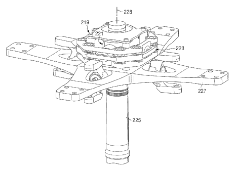
Figures 10 and 11 illustrate a portion of a rotor system, which may be rotor
system 207 or 209, having a constant-velocity drive system 219. Figure 10 is
an
oblique view showing system 219 as assembled, and Figure 11 is an oblique view
showing system 219 as exploded. Drive system 219 comprises a gimbal mechanism
221 and a torque-combining differential mechanism 223 and provides for the
transfer of
torque from rotor mast 225 to yoke 227 for driving yoke 227 in rotation with
mast 225
about mast axis 228 while allowing yoke 227 to pivot relative to rotor mast
225 during
flapping.
Referring now to Figure 11, a trunnion carrier 229 is affixed to mast 225 with
splines 231. Trunnion carrier 229 is preferably formed as a unitary piece and
has two
opposing pairs of trunnions 233 extending therefrom, the pairs of trunnions
233 defining
perpendicular gimbal axes 235, 237. Gimbal mechanism 221 comprises first
gimbal
239 and second gimbal 241, and gimbals 239, 241 are preferably identical in
construction. Each gimbal 239, 241 comprises a pair of opposing inner bearings
243
and a pair of opposing outer bearings 245, such that each pair of inner
bearings defines
an axis 247 and each pair of outer bearings 245 defines an axis 249. Axes 247,
249 of
each gimbal 239, 241 are perpendicular to each other. When assembled onto
trunnion
carrier 229, each inner bearing 243 engages one of trunnions 233, so that axis
247 of
each gimbal is coaxial with one of axes 235, 237. This configuration allows
each gimbal
239, 241 to pivot on its inner bearings 243 about one of axes 235, 237 and
relative to
trunnion carrier 229 and mast 225. It should be noted that inner bearings 243
and outer
CA 02711149 2010-06-29
WO 2009/088495 PCT/US2008/050213
-13-
bearings 245 may be any appropriate type of bearing, such as cylindrical,
ball, conical,
and/or or laminated.
Torque-combining mechanism 223 comprises first ring 251, middle ring 253, and
second ring 255. First ring 251 and second ring 255 are preferably identical
in
construction, and middle ring is located between rings 251, 255. Each of first
ring 251
and second ring 255 comprises a pair of opposing bearing housings 257, and
each pair
of bearing housings 257 defines an axis 259. When each ring 251, 255 is
assembled
onto one of gimbals 239, 241, each bearing housing 257 engages one of outer
bearings
245, so that axis 249 of each gimbal is coaxial with axis 259 of the
associated ring 251,
255. This configuration allows each ring 251, 255 to pivot on outer bearings
245 about
one of axes 249 and relative to gimbals 239, 241. Trunnion carrier 229, while
shown
within middle ring 253, is not directly attached to middle ring 253.
Each of first ring 251, middle ring 253, and second ring 255 has a plurality
of
cylindrical bores 261, 263 that extend in a direction generally parallel to
mast axis 228.
When assembled, bores 261, 263 on rings 251, 253, 255 are nominally coaxial
and are
connected using pin assemblies 265, which are shown as installed in bores 261
of
middle ring 241.
Figure 12 is an exploded view of a pin assembly 265, which comprises a pin 267
and pair of opposing ball joint assemblies 269. Pin 267 comprises a central
shaft 271,
two ball ends 273 at opposing ends of shaft 271, and a central cylindrical
member 275.
Cylindrical member 275 is carried within cylindrical bearing 277 (shown split
in half in
the figure), which is configured to be installed in one of bores 263 of middle
ring 253.
When assembled, axis 279 of each pin assembly is oriented to extend generally
radially
relative to mast axis 228, and this configuration allows for rotation of pin
assembly 265
about axis 279 relative to middle ring 253. Each ball joint assembly 269 is
configured to
be installed in one of bores 261 of rings 251, 255 and comprises a spherical
bearing
281, a cylindrical bearing 283, and a cylindrical sleeve 285. Each of ball
ends 273 is a
rigid ball end is retained within spherical bearing 281. Likewise, spherical
bearing 281
CA 02711149 2010-06-29
WO 2009/088495 PCT/US2008/050213
-14-
is retained within cylindrical bearing 283, and cylindrical bearing 283 is
retained within
cylindrical sleeve 285. When installed, cylindrical sleeve 285 is mounted in
one of
bores 263 of rings 251, 255. The configuration of each ball joint assembly 269
allows
pin assembly 265 to rotate about a focus at the center of each ball end 273
relative to
rings 251, 255. The assembly of rings 251, 253, 255 and pin assemblies 265
allows for
first ring 251 and second ring 255 to rotate in opposite directions relative
to middle ring
253 while providing a constant torque path from gimbals 239, 241 to middle
ring 253,
which serves as the output component for mechanism 223. It should be noted
that
each of bearings 281, 283 are preferably laminated bearings, and that
cylindrical
member 275 may be configured in a different form, such as a ball joint, in
alternate
embodiments.
Referring again to Figure 11, cylindrical barrels 287 are fixedly attached to
middle
ring 253 and extend in directions generally parallel to mast axis 228 when
system 219 is
in the nominal position. Barrels 287 are configured to fit over posts 289,
which extend
upward from yoke 227 between an upper hub spring 291 and a lower hub spring
293,
and barrels 287 transfer torque from middle ting 253 to yoke 227 through posts
289.
Posts 289 may be formed as components of lower hub spring 293, as shown, or
posts
may extend upward from yoke 227 and locate hub spring 291, 293 relative to
yoke 227.
In operation, torque is transferred from mast 225 to trunnion carrier 229
through
splines 231. Torque is then transferred from trunnions 233 to gimbals 239, 241
through
inner bearings 243 and from gimbals 239, 241 to rings 251, 255 through outer
bearings
245. Torque is then transferred from rings 251, 255 to middle ring 253 through
pin
assemblies 265 and from ring 253 to yoke 227 through barrels 287 and posts
289. The
torque is transferred from mast 225 to yoke 227 even while allowing for yoke
227 to
pivot relative to mast 225 about gimbal axes 235, 237.
Figures 13 and 14 illustrate a portion of a rotor system, which may be rotor
system 207 or 209, having a constant-velocity drive system 295. Figure 13 is
an
oblique view showing system 295 as assembled, and Figure 14 is an oblique view
CA 02711149 2010-06-29
WO 2009/088495 PCT/US2008/050213
-15-
showing system 295 as exploded. Drive system 295 comprises a gimbal mechanism
297 and a torque-combining differential mechanism 299. Drive system 295
provides for
the transfer of torque from rotor mast 225 to yoke 227 for driving yoke 227 in
rotation
with mast 225 about mast axis 228 while allowing yoke 227 to pivot relative to
rotor
mast 225 during flapping.
Referring to Figure 14, trunnion carrier 301, which has a configuration
similar to
that of trunnion carrier 229, described above, is preferably formed as a
unitary piece
and is affixed to mast 225 with splines 231. Trunnion carrier 301 has two
opposing
pairs of trunnions 303 extending therefrom, the pairs of trunnions 303
defining
perpendicular gimbal axes 305, 307. Gimbal mechanism 297 comprises first
gimbal
309 and second gimbal 311, and gimbals 309, 311 are preferably identical in
construction. Each gimbal 309, 311 comprises a pair of opposing inner bearings
313
and a pair of opposing outer bearings 315, such that each pair of inner
bearings defines
an axis 317 and each pair of outer bearings 315 defines an axis 319. Axes 317,
319 of
each gimbal 309, 311 are perpendicular to each other. When assembled onto
trunnion
carrier 301, each inner bearing 313 engages one of trunnions 303, so that axis
317 of
each gimbal is coaxial with one of axes 305, 307. This configuration allows
each gimbal
309, 311 to pivot on its inner bearings 313 about one of axes 305, 307 and
relative to
trunnion carrier 301 and mast 225. It should be noted that inner bearings 313
and outer
bearings 315 may be any appropriate type of bearing, such as cylindrical,
ball, conical,
and/or or laminated.
Torque-combining mechanism 299 comprises first ring 321, second ring 323, and
cage 325. First ring 321 and second ring 323 are preferably identical in
construction,
and each ring 321, 323 comprises a pair of opposing trunnions 327 that define
axes
329. When each ring 321, 323 is assembled onto one of gimbals 309, 311, each
pair of
trunnions 327 engages outer bearings 315 of one of rings 321, 323, so that
axis 319 of
each gimbal is coaxial with axis 329 of the associated ring 321, 323. This
configuration
allows each ring 321, 323 to pivot on outer bearings 315 about one of axes 319
and
CA 02711149 2010-06-29
WO 2009/088495 PCT/US2008/050213
-16-
relative to gimbals 309, 311. It should be noted that second ring 323, while
shown near
yoke 227, is not directly attached to yoke 227.
In the present embodiment, torque is transferred from first ring 321 and
second
ring 323 to yoke 227 through cage 325, which serves as the output component
for
mechanism 299 and is attached directly to yoke 227. Cage 325 comprises a
central
hub spring 331 and four arms 333 extending therefrom and arrayed around hub
spring
331. Referring also to Figure 15, each arm 333 comprises upper endplate 335,
lower
endplate 337, and a bar 339 extending between endplates 335, 337. Each upper
endplate 337 rigidly connects the associated bar 339 to hub spring 331, and
each
endplate 335, 337 extends generally perpendicularly to bar 339. A transfer
block 341
extends inwardly from an inner surface of each bar 339. Wedge assemblies 343,
which
are detailed below, are located adjacent each transfer block 341 and are used
to
transfer forces from rings 321, 323 and through transfer blocks 341 into arms
333 of
cage 325. Endplates 337 are rigidly fastened to yoke 227, which allows for
torque from
mast 225 to be transferred through trunnion carrier 301, into gimbal mechanism
297,
then into torque-combining differential mechanism 299, and through cage 325
into yoke
227 for driving yoke 227 in rotation with mast 225.
Referring to Figures 15 and 16, details of one of arms 333 and two wedge
assemblies 343 are illustrated. Wedge assemblies 343 provide a similar
function as pin
assemblies 265, described above, in that wedge assemblies 343 allow for
relative
rotation of rings 321, 323 about mast axis 228 while forces are continuously
transferred
from rings 321, 323 into transfer block 341.
Each wedge assembly 343 comprises two wedges 345, with each wedge 345
having an inclined face 347 and a curved face 349. Pairs of wedges 345 are
located on
opposing sides of transfer block 341 and oriented so that their inclined faces
form a "V"
and their curved faces are aligned, as shown in the figures. To limit or
prevent wear on
faces 347, 349, bearings 351 are located adjacent faces 347, and curved
bearings 353
are located adjacent faces 349. In addition, a bearing 355 is located between
adjacent
CA 02711149 2010-06-29
WO 2009/088495 PCT/US2008/050213
-17-
wedges 345. Bearings 351, 353, 355 are preferably elastomeric bearings, though
any
appropriate bearing may be used. As shown in the exploded view of Fig. 16,
transfer
block 341 has opposing curved faces 357, which are shaped to receive curved
bearings
349 on wedges 345. The curvature allows for wedges 345 to rotate about an axis
generally parallel to mast axis 228 while remaining in contact with faces 357
of contact
block 341.
In order to transfer forces from ring 321, 323 to transfer blocks 341, each
wedge
assembly 343 engages trapezoidal notches 359 on rings 321, 323, as shown in
Figure
14. Upon assembly, notches 359 of each ring 321, 323 are nominally aligned
with
notches 359 of the other of rings 321, 323 to form hexagonal enclosures. The
enclosures are sized to receive an upper or lower portion of transfer block
341 and the
two adjacent wedges 345. This configuration provides for transfer of forces
from each
ring 321, 323 to transfer blocks 341 through pairs of wedges 345 and also
allows for
first ring 321 and second ring 323 to rotate in opposite directions relative
to each other
while providing a constant torque path from gimbals 309, 311 to cage.
Additional
bearings 361, which are preferably elastomeric, are located between rings 321,
323 are
endplates 335, 337 and between notches 359 and the ends of transfer blocks
341.
In operation, torque is transferred from mast 225 to trunnion carrier 301
through
splines 231. Torque is then transferred from trunnions 303 to gimbals 309, 311
through
inner bearings 313 and from gimbals 309, 311 to rings 321, 323 through outer
bearings
315. Torque is then transferred from rings 321, 323 to cage 325 through wedge
assemblies 343, and from cage 325 to yoke 227 through endplates 337. The
torque is
transferred from mast 225 to yoke 227 even while allowing for yoke 227 to
pivot about
gimbal axes 305, 307 relative to mast 225.
This description includes reference to illustrative embodiments, but it is not
intended to be construed in any limiting sense. Various modifications and
combinations
of the illustrative embodiments, as well as other embodiments, will be
apparent to
persons skilled in the art upon reference to this description.