Note: Descriptions are shown in the official language in which they were submitted.
DEVICE FOR REGULATING BLOOD FLOW
1. Field of the Invention
The subject invention is directed to a device for regulating blood flow in the
venous
system, and more particularly, to an implantable valve device for regulating
the flow of
blood through a blood vessel.
2. Description of Related Art
The blood system, and in particular the venous blood system of the legs and
arms is provided with valves that are uniquely located in a manner so as to
ensure
that blood will not flow back upstream in the direction from which it has been
pumped from the heart. In the arms and legs, there is a deep venous system and
a
surface (superficial) venous system.
Due to various causes, thrombosis can occur in the deep venous system. Blood
thinning
can alleviate this problem. However, valves do not effectively close and often
leak when
the blood in thinned. This can cause increased venous blood pressure in the
direction of
the ankles, which can lead to a variety of problems including pain, swelling,
varicose
veins
1
CA 2711245 2017-06-30
CA 02711245 2010-06-30
WO 2009/088957 PCT/US2009/000001
and ulcers. Complaints of this type are wide spread among those who spend
prolonged
periods of time in a standing position, for instance, surgeons.
The surface venous system of the leg is relatively weaker than the deep venous
system, and it has the tendency to spontaneously widen due to the increased
pressure of
blood from above. This widening prevents the valves from functioning
effectively and can
lead to varicose veins, which are both unattractive and painful. Major surgery
is often
required to treat these blood vessel problems. For example, varicose veins are
treated by
either closing off the vein, which leads to a reduced blood flow capacity and
increased
pressure on surrounding blood vessels to ensure blood drainage, or by
completely
removing the varicose veins, which leads to the same problem. The deep veins
require
invasive surgery and because of the swelling, risk of infection and trauma is
seldom
attempted. In either case, the treatment of the surface veins does not treat
the failed valves
in the deep system, thereby causing the continued pressure and back flow into
the legs. The
subject invention is directed to a device for obviating problems of this type.
SUMMARY OF THE INVENTION
The subject invention is directed to a new and useful implantable valving
device for
mechanically regulating blood flow through a blood vessel.
The present invention provides in one aspect an implantable device for
regulating
blood flow through a blood vessel comprising an elongated support dimensioned
and
configured to be implanted in a blood vessel and a valve membrane. The support
includes
axially spaced apart first and second substantially annular support portions
and a first
linking member linking the axially spaced apart portions to one another. The
valve
membrane extends between the axially spaced apart support portions and has an
upper
2
CA 02711245 2010-06-30
WO 2009/088957 PCT/US2009/000001
portion, a lower portion and an intermediate portion. The valve membrane
includes a first
region and a second lower region wherein the first region is folded over the
first linking
member for attachment and the second region is adjacent the first region and
unattached to
the first linking member. The second region is movable between a first
position to enable
blood flow and a second position to inhibit blood flow.
The device preferably further includes a third region folded over for
attachment to
the first linking member, wherein the second region is positioned between the
first and
third region.
In one embodiment, the first linking member is curved and traverses a
longitudinal
axis of the device. In some embodiments, the support is formed at least in
part from a
shape memory alloy material and the valve membrane is formed at least in part
from
ePTFE. Preferably, the valve membrane is coated at least in part with an anti-
clotting
agent. The support can be integrally formed from a laser cut tube.
The device may further include a second linking member, wherein the valve
membrane has a fourth region folded over the second linking member for
attachment.
In some embodiments, the upper portion of the valve membrane is attached to a
bottom region of the first support portion and the lower portion of the
membrane is
attached to a top region of the second support portion, wherein a section of
the lower
portion of the membrane is wrapped around a section of the top region of the
support
portion.
The present invention also provides an implantable device for regulating blood
flow through a blood vessel comprising an elongated support dimensioned and
configured
to be implanted in a blood vessel and a valve membrane supported by the
support and
3
CA 02711245 2010-06-30
WO 2009/088957 PCT/US2009/000001
including first, second and third portions. The first portion is attached at a
first region of
the support, the third portion is attached at a second region of the support,
and the second
portion is positioned between the first and third portions and unattached to
the support. The
second portion is movable with respect to the support between a first position
to enable
blood flow and a second position closer to the support to inhibit blood flow.
Preferably, the first and third portions of the valve membrane form a flap
wrapped
around a portion of the support, and the second portion forms a flap movable
with respect
to the first and third portions to create an opening for antegrade blood flow.
In a preferred
embodiment, the second portion of the valve membrane is closer to a top region
than a
bottom region of the valve membrane.
The valve membrane may further comprise a fourth portion separate from the
second portion and unattached to the support, the fourth portion movable with
respect to
the support between a first position to enable blood flow and a second
position to inhibit
blood flow.
In one embodiment, the support includes first and second linking members
extending between first and second annular portions of the support, and the
second portion
forms a first flap adjacent the first linking member and the fourth portion
forms a second
flap adjacent the second linking member, the flaps each creating a space
between the flap
and the respective linking member during antegrade blood flow to enable blood
flow
through the space and the flap closing the space during retrograde blood flow.
The present invention also provides an implantable device for regulating blood
flow through a blood vessel comprising an elongated support dimensioned and
configured
to be implanted in a blood vessel and engagable with a blood vessel wall and a
valve
4
CA 02711245 2010-06-30
WO 2009/088957 PCT/US2009/000001
membrane. The support includes axially spaced apart first and second support
portions and
a first linking member linking the axially spaced apart portions to one
another. The valve
membrane is attached to the linking member, the valve membrane having an upper
portion
attached to a first section of the support and a lower portion attached to a
second section of
the support. The valve membrane has an enabling condition to enable blood flow
when
blood flows in one direction and an inhibiting condition to inhibit blood flow
when blood
flows in an opposite direction. The upper attached portion of the membrane and
the lower
attached portion of the membrane remain substantially fixed in position in
both the
enabling condition and the inhibiting condition and the lower and upper
attached portions
remain adjacent opposing regions of the vessel wall in both conditions.
The valve membrane preferably includes an intermediate portion between the
upper
and lower attached portions and a first flap in the intermediate portion, the
first flap
unattached to the support and movable for creating the flow inhibiting and
flow enabling
conditions while the upper and lower attached portions remain fixed.
The present invention also provides an implantable device for regulating blood
flow through a blood vessel comprising an elongated support dimensioned and
configured
to be implanted in a blood vessel and a valve membrane supported by the
support and
having a first condition to enable blood flow and a second condition to
inhibit blood flow.
The valve membrane is positioned in the vessel at a first angle extending
across the vessel
to traverse a longitudinal axis of the vessel such that opposite ends of the
membrane are
adjacent opposing walls of the vessel, and the membrane remains substantially
at the first
angle in the first and second conditions.
5
CA 02711245 2010-06-30
WO 2009/088957 PCT/US2009/000001
Preferably the valve membrane has a first region unattached to the support
formed
by at least one cut in the membrane and creating an opening adjacent the
support during
antegrade blood flow. Preferably, the first unattached region moves adjacent
the support to
close the opening during retrograde blood flow.
In a preferred embodiment, the valve membrane has a second region unattached
to
the support and spaced from the first region, the second unattached region
formed by at
least one cut in the membrane and creating an opening adjacent the support
during
antegrade blood flow. In this embodiment, the second unattached region moves
adjacent
the support to close the opening during retrograde blood flow.
In one embodiment, the valve membrane has an upper region and a lower region,
and the first unattached region and second unattached region are closer to the
top region
than the bottom region.
BRIEF DESCRIPTION OF THE DRAWINGS
So that those skilled in the art to which the subject invention appertains
will readily
understand how to make and use the apparatus of subject invention without
undue
experimentation, preferred embodiments thereof will be described in detail
hereinbelow
with reference to certain figures, wherein:
Figure 1 is a perspective view of the flow regulating device of the present
invention,
prior to full assembly;
Figure 2 is a perspective view of the support of the flow-regulating device of
Figure
1;
6
CA 02711245 2010-06-30
WO 2009/088957 PCT/US2009/000001
Figure 3 is a Side perspective view of the flow regulating device illustrating
how the
membrane is attached to the frame;
Figure 4 is a front perspective view of the top (distal) portion of the flow
regulating
device of Figure 1 showing the membrane in the closed position;
Figure 5A is a side perspective view showing the membrane in the open
position;
Figure 5B is a side perspective view similar to Figure 5A showing the membrane
in
the closed position;
Figure 6A is a cross-sectional view of the identified area of Figure 5A
showing the
membrane in the open position, resulting from antegrade blood flow;
Figure 6B is a cross-sectional view of the identified area of Figure 6A
showing the
membrane in the closed position, resulting from retrograde blood flow;
Figure 6C is a top view of the upper region of the membrane of Figure 5B
showing
the membrane in the closed position;
Figure 6D is a top view of the upper region of the membrane of Figure 5A
showing
the membrane in the open position;
Figure 6E is a top view of the upper region of an alternate embodiment of the
membrane shown in the open position;
Figure 7 is a view similar to Figure 4 showing another alternate embodiment of
the
membrane with flaps forming larger openings for increased antegrade blood
flow;
Figure 7A is a cross-sectional view similar to Fig 6B except showing the
membrane
of Figure 7 in the closed position; and
Figure 8 is a drawing of the anatomy of the patient showing two examples of
locations of placement of the flow regulating device.
7
CA 02711245 2010-06-30
WO 2009/088957 PCT/US2009/000001
DETAILED DESCRIPTION OF PREFERRED EMBODIMENTS
Referring now to the drawings wherein like reference numerals identify similar
or
like components throughout the several views, there is illustrated a flow
regulating device
constructed in accordance with a preferred embodiment of the subject
invention, and
designated generally by reference numeral 10. Regulating device 10 includes an
elongated
support 12 that has upper and lower substantially annular ring portions 14 and
24, each
having a series of rounded V-shaped apices 15a facing in an upward direction
and a series
15b facing in a downward direction. That is, the upper or distal (with respect
to the
direction of blood flow) ring portion 14 has a first series of angled struts
13a forming a V
and a second series of angled struts 13b forming an inverted V which together
form a
group of closed substantially diamond shaped cells 19 connected at region 17.
Similarly,
the lower or proximal (with respect to the direction of blood flow) ring
portion 24 has a
first series of angled struts 29a and a second series of angled struts 29b,
facing in opposite
directions and forming closed substantially diamond shaped cells 28 connected
at region
27. The cells 28 have upper. apices 25 and lower apices 26. For clarity, not
all of the
identical parts in the drawings are labelled. Note that in the preferred
embodiment, the
rings and linking member (described below) are preferably integral so that
terms "joined",
"connected", etc. are used for ease of description.
Support 12 has two curved linking or connecting members 21a, 21b, best shown
in
Figure 2 in which the membrane is removed for clarity. The top of each
connecting
member 21a, 21b extends from a common lower apex 15b of one of the pairs of
angled
struts 13b of upper ring 14 (see also Figs. 3 and 4) The lower end of
connecting members
8
CA 02711245 2010-06-30
WO 2009/088957 PCT/US2009/000001
21a, 21b extend from separate upper apices 25a, 25b, respectively, of cells 28
of lower ring
24. In the illustrated embodiment, the apices 25a, 25b, are about 36 degrees
apart as ten
cells are formed. However, a different number of cells can be provided with
different
spacing between apices. Also, it should be appreciated that the connecting
members can
extend from other apices of lower ring 24 or upper ring 14. The connecting
members 21a,
21b have a curve or twist extending close to about 180 degrees (and extending
substantially across the vessel when implanted) so that an upper end is
connected to one
end (viewed radially/transversely) of the device 10 and the lower end is
connected to an
opposite end (viewed radially/transversely) of the device 10. That is, with
ten closed cells
in the illustrated embodiment, apex 15b is approximately 162 degrees out of
phase from
apex 25a and from apex 25b. Other spacing and alternate number of cells is
also
contemplated.
Although two connecting members are shown, one connecting member or more
connecting members could be provided. Also, the connecting members could be
spaced
further or closer apart and have different curves than shown.
The rings 14, 24 are collapsed to a reduced diameter (profile) position for
delivery.
The rings 14, 24, when implanted, are substantially perpendicular to the
direction of blood
flow. Preferably, the rings 14, 16 in their expanded (deployed) configuration
are larger in
diameter than the internal diameter of the target vessel to apply a sufficient
radial force
against the vessel to ensure that the device remains in a desired position and
orientation
after implantation. For example, for use in an 8mm vessel, the rings could
have an
expanded outer diameter of about 10mm 'and preferably could be collapsed
sufficiently to
9
be delivered through a 12Fr (4mm) delivery catheter. Others ring diameters are
also
contemplated.
The support 12 is preferably composed of shape memory material, such as
NitinolTM or ElgiloyTM, with a shape memorized larger diameter configuration
as
shown in the drawings. In the illustrated embodiment, the support is laser cut
from a tube
so that the connecting members and rings are integral. However, it is also
contemplated
that alternatively the support can be formed from wire(s). Also, it should be
appreciated
that instead of being integral, separate members could be provided, with
separate rings
joined by separate linking (connecting) members.
Device 10 includes a valve member or membrane 50 that is operatively
associated with support 12 for regulating the flow of blood through a vessel
by moving
between open and closed positions. Membrane 50 is preferably formed from a
sheet of
ultra thin membrane material such as a ePTFE material or the like. It is
envisioned that the
membranes disclosed herein could be bonded or otherwise coated with an anti-
clotting or
anti-coagulant/anti-thrombogenic agent such as HeparinTM and/or an anti-
proliferative
coating, to retard the body's desire to reject the implant. In a preferred
embodiment, the
membrane is coated with an anti-thrombogenic agent and the frame is coated
with an anti-
proliferative agent, such as DexamethasoneTM by way of example.
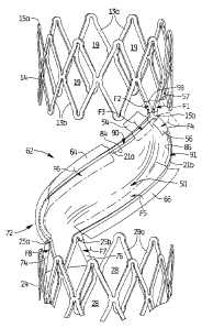
As shown, valve membrane 50 has an upper portion 52, an intermediate
portion 62, and a lower portion 72. With reference to Figure 3 which
illustrates how the
membrane 50 is attached to support 12 in manufacture, the top portion 52 has
first and
second flaps 54, 56 which are folded down over respective connecting members
21a, 21b
and attached to the membrane to secure the upper portion 52 of membrane 50
about the
support 12. Figure
CA 2711245 2017-06-30
CA 02711245 2010-06-30
WO 2009/088957 PCT/US2009/000001
3 illustrates flap 56 already folded in the direction of arrow F4 from its
unfolded position
shown in phantom. Figure 3 also illustrates flap 54 in its unfolded position
before
movement in the direction of arrow F3 in manufacture to its folded position
depicted in
phantom. Flaps 57 and 59 at the uppermost region of membrane 50 are wrapped
around
-- struts 13b in the direction of arrows Fl, F2, respectively.
With continued reference to Figure 3, the intermediate portion 62 of membrane
50
has flaps 64, 66 for connection to linking (connecting) members 21a, 21b,
respectively.
Flap 64 is shown in a mostly unfolded position to be folded in the direction
of arrows F6 to
its folded position shown in phantom where it is attached to the membrane 50.
Flap 66 is
-- shown in its unfolded position to be folded in the direction of arrows F5
to its folded
position depicted in phantom.
Lower portion 72 of membrane 50 has flaps 74 and 76 which are each folded
around a separate strut 29a. Arrows F8, F7, respectively, illustrate the
direction of the fold.
Cuts in the membrane 50 create an unattached flap 84 between upper attached
flap
-- 54 and intermediate attached flap 64 and an unattached flap 86 between
upper attached flap
56 and intermediate attached flap 66. These unattached flaps 84, 86 are
positioned
adjacent the respective connecting member 21a, 21b as shown, but create a
respective
opening 90, 91 for blood flow between the membrane 50 and connecting members
21a,
21b as described below. Note, alternatively, the flaps 84, 86 can extend over
the
-- connecting member, as long as it remains unattached and creates a
sufficient space from
the linking member to create a sufficiently sized opening to allow blood flow
therethrough.
Note that Figure 1 shows the membrane 50 with the flaps open, prior to
connection
in manufacture, to illustrate how it is wrapped around the support 12 and
connected to
11
CA 02711245 2010-06-30
WO 2009/088957 PCT/US2009/000001
other portions of the membrane for securement/attachment of the membrane to
the support
12. The flaps, after wrapping over/around the region of support 12, can be
connected to
the membrane body by welding, adhesive, suturing or other methods. Also, an
intermediary material can be used to facilitate welding, such as polyurethane
or
polycarbonate/polyurethane impregnated or otherwise combined with the ePTFE
material.
It is also contemplated that the membrane can be attached to the support 12
itself by
methods such as by adhesive or use of suture material.
As can be appreciated, the body portion of the membrane 50 extends
substantially
if not entirely across the expanse of the vessel in the open position.
However, the openings
90 and 91 adjacent the unattached flaps 84, 86 provide a sufficient gap for
the necessary
amount of blood flow, it being appreciated by applicants that a normally
functioning valve
is only open about 35%. In some embodiments, the openings in the membrane
created by
the space between flaps 84, 86 and the support create a space gap in the range
of about 5%
to about 15% of the diameter of the vessel. In the alternate embodiment
depicted in Figure
7, larger openings 90' and 91' are formed to allow more antegrade blood flow.
In these
large opening embodiments, a space (opening) can be created preferably
representing
about 15% to about 45%, and more preferably from about 15% to about 30% of the
diameter of the vessel. (In all other respects the regulating device of Figure
7 is identical to
that of Figure 4 and the corresponding parts are labelled by numerals with a
prime
designation and therefore are not discussed herein). These percentages are
defined in
terms of the diameter of the blood vessel. For example, if a rectangular
opening is formed
of dimension of 2mm x 4mm, and is placed in a lOmm vessel, the cross section
occupied
by the two openings (about 16mm) would be about 20% of the overall diameter of
the
12
CA 02711245 2010-06-30
WO 2009/088957 PCT/US2009/000001
vessel (about 78mm). It should be appreciated that the foregoing ranges and
percentages
are provided by way of example and other size openings creating a different
percentage
opening are also contemplated. Also, other shape openings can be provided
other than
rectangular, including square, semicircular, etc. Figure 6E shows by way of
example
substantially semicircular openings 90", 91" formed by flaps 84". 86",
respectively.
Movement of the membrane 50 between an open (blood flow enabling)
position/condition to allow antegrade blood flow and a closed (blood flow
inhibiting
position/condition) to essentially block flow are shown in respective Figures
5A and 5B,
and shown in more detail in Figures 6A-6D. In the closed position, however, a
minimal
amount of blood flow is allowed as will be discussed below.
More specifically, and with reference to Figure 5A, blood flowing through the
blood vessel V in the downstream direction (antegrade flow) indicated by arrow
"D" will
act against the valve membrane 50 in such a manner as to push the body portion
upwardly
as viewed in the drawing, creating a concave belly on the underside. The blood
will travel
along the concave surface and up the membrane and the blood pressure will
force the flaps
84 and 86 upwardly, separating (spreading) them from the respective connecting
members
21a, 21b as also shown in Figures 6A and 6D to form an opening or gap.
After the pulsed blood travels in the direction of arrow D1 (Fig. 5A), through
the
openings (spaces) 90, 91, the blood backs up in the direction of arrow C of
Figure 5B.
This retrograde blood flow will act against the angled body of the membrane
50, forcing it
downwardly as viewed in Figure 5B to form a convexity on its underside. This
downward
pressure will force flaps 84, 86 downwardly adjacent to the connecting members
21a, 21b,
respectively, and against the connecting member as shown for example in Figure
6B and
13
CA 02711245 2010-06-30
WO 2009/088957 PCT/US2009/000001
6C, thus essentially closing the openings 90, 91 to prevent blood flow
therethrough.
However, a small amount of blood will force its way between the membrane 50
and the
vessel wall as depicted by arrow Cl in Figure 5B, thereby reducing stasis or
stagnation that
could lead to clotting. In embodiments wherein a larger flap is utilized to
create a larger
opening, such as in the embodiment of Figure 7, the flap 84' (and 86', not
shown) in the
closed position would lie adjacent the connecting members, and extend
underneath the
connecting member (e.g. connecting member 21a') to lie against the vessel wall
as shown
in Figure 7A, thereby inhibiting blood flow.
It should be appreciated that the membrane extends at an angle across the
vessel of
about 50 to about 70 degrees to help direct the blood flow and continuously
wash the
membrane body to prevent blood stagnation. (Other angles are also
contemplated) More
specifically, blood contacting the body portion of the membrane 50 in the open
position
will be directed upwardly, along the concave surface, thereby washing the
membrane body
to wash away clots to reduce the likelihood of clotting. In the closed
position, blood
contacting the membrane body will be directed downwardly along the angled body
to wash
the opposing side of the membrane to likewise reduce the likelihood of
clotting.
As can be appreciated, the membrane 50 remains at substantially the same angle
across the blood vessel in the open (flow allowing) and closed (flow
inhibiting)
positions/conditions. That is, as shown in Figures 5A and 5B, the upper region
of the
membrane 50 is adjacent one side of the vessel wall in the open (flow
allowing) position-
The upper region remains adjacent the same wall in the closed (flow
inhibiting) position.
Similarly, the lower region of the membrane 50 is adjacent an opposite side of
the vessel
wall, and remains adjacent that wall in both the open and closed positions of
Figures 5A,
14
5B, respectively. Thus, the upper and lower attached regions of the membrane
remain in
substantially the same position.
One example of the location of placement of the flow regulating device in
a patient's leg is shown in Figure 8 with areas Al and A2 showing possible
placement sites of the device, e.g. upstream or downstream of the native valve
V.
If composed of shape memory, the device will automatically expand to the
position shown either upon release from a delivery member or in response to
temperature change. However, if composed of other materials, the device can be
designed to automatically expand due to the springiness of the material or can
alternatively be implanted in a blood vessel using a balloon catheter (not
shown) as
described in copending U.S. patent application serial no. 11,801,691. That is,
rings 14 and
24 can be moved from a closed position to an expanded position by inflating
the balloon
or by use of a mechanical expander. Upon expansion, the rings 14 and 24 apply
a force
against the vessel wall, thereby being retained therein. The balloon or
mechanical
expander is then deflated and the catheter is removed from the blood vessel so
the device
10 can regulate the flow of blood through the vessel in the manner described
above.
In the embodiments disclosed herein showing substantially circular rings, it
should be understood that the rings can be shaped to have a size larger than
the diameter of
the vessel and therefore, depending on the size of the vessel, may not assume
a circular
shape but have an oval shape pressing against the vessel wall toward a
circular
configuration. While the above description contains many specifics, those
specifics should
not be construed as limitations on the scope of the disclosure, but merely as
exemplifications of
CA 2711245 2017-06-30
CA 02711245 2010-06-30
WO 2009/088957 PCT/US2009/000001
preferred embodiments thereof. Those skilled in the art will envision many
other possible
variations that are within the scope and spirit of the disclosure.
16