Note: Descriptions are shown in the official language in which they were submitted.
CA 02711403 2015-09-10
POROUS BIOCOMPATIBLE POLYMER MATERIAL AND METHODS
TECHNICAL FIELD
The present structures and methods relate toporuus polymer
materials and methods for making porous polymer materials and structures.
Example structures include, but are not limited to, spacers for spinal fusion,
Craniomaxillofacial (CMF) structures, other materials and structures for bone
replacement.
BACKGROUND
Spinal fusion is a common technique used to treat chronic back
pain caused by degenerated or herniated disk. The technique involves the
removal of a disc between two vertebrae and replacing it with an intex-
vertebral
spacer. The intervcrtebral spacer maintains spacing between the two vertebrae
and preferably results in fusion through the spacer. The intervertebral
spacers
may be constructed of autogenic bone tissue taken from a patient's own bone.
Allogenic spacers are constructed of bone harvested from donors. Artificial
spacers are currently the most common spacer type and may be constmeted of
metallic material such as titanium or stainless steel or polymers such as
polyetheretherketone (PEEK).
PEEK has recently become popular due to its biocompatibility
and naturally radiotranslucent characteristics, resulting in limited
interference
with x-ray and CT imaging. However, while PEEK is biocompatible, bone treats
it as a foreign body during the remodeling process and isolates it with a
fibrous
tissue capsule. This fibrous tissue prevents direct bony apposition and
adhesion
CA 02711403 2010-07-05
WO 2009/099559
PCT/US2009/000604
to the implant. Other materials, such as titanium, allow for direct bony
apposition and ongrowth, but they are typically not radiotranslucent and it
becomes difficult to assess the fusion formation.
Other areas where PEEK is used as an orthopedic biomaterial
experience similar fibrous encapsulation. Such indications include custom
machined bodies that are used to fill defects in the skull and cranium. With
PEEK, MRI and CT imaging is generally easier as compared to titanium, but the
implant is never fully incorporated into the bone and soft tissue does not
adhere
to the implant.
Ceramic materials such as calcium phosphates, (3-TCP,
hydroxyapatites and the like allow for direct bony apposition much like
titanium.
However, they are typically limited in their strength and toughness.
Therefore, it
is desireable to construct a material that combines more of the desired
properties
from other individual materials described above, such as toughness and
strength,
less interference with MRI, X-ray or CT imaging, tissue adhesion, etc.
BRIEF DESCRIPTION OF THE SEVERAL VIEWS OF THE
DRAWINGS
The foregoing summary, as well as the following detailed
description of preferred embodiments of the invention, will be better
understood
when read in conjunction with the appended drawings. For the purposes of
illustrating the polymeric porous bodies for promoting ingrowth/throughgrowth
of the present application, there is shown in the drawings preferred
embodiments. It should be understood, however, that the application is not
limited to the precise arrangements and instrumentalities shown. In the
drawings:
Fig. 1A illustrates a top view of a porous biocompatible material
according to an embodiment of the invention.
Fig. 1B illustrates a top view of a porous biocompatible material
according to the prior art.
2
CA 02711403 2010-07-05
WO 2009/099559
PCT/US2009/000604
Fig. 2 illustrates a top plan view of PEEK granules with O-TCP
on the surface according to an embodiment of the invention.
Fig. 3 illustrates a top perspective view of a porous spacer with a
through hole according to an embodiment of the invention.
Figs. 4A, 4B, and 4C illustrate a front plan view, a front sectional
perspective view, and a front exploded view, respectively, of a spacer having
a
solid core according to an embodiment of the invention.
Figs. 5A, 5B, and 5C illustrate a front plan view, a front
perspective sectional view, and a front perspective exploded view of a spacer
having a solid band according to an embodiment of the invention.
Figs. 6A, 6B, and 6C illustrate a top perspective view, a front
perspective view, and a top perspective exploded view of another spacer with a
solid portion according to an embodiment of the invention.
Figs. 7A, 7B, and 7C illustrate a front perspective sectional view,
a side perspective exploded view, and a front perspective view of another
spacer
according to an embodiment of the invention.
Fig. 8 illustrates a front perspective view of a total disc
replacement implant for disc arthroplasty according to an embodiment of the
invention.
Figs. 9A, 9B, and 9C illustrate a front perspective view, a top
plan view, and a side perspective view of a spacer and a fixation plate
according
to an embodiment of the invention.
Fig. 10 illustrates a side perspective view and a side perspective
sectional view of a spacer including an instrument engagement feature
according
to an embodiment of the invention.
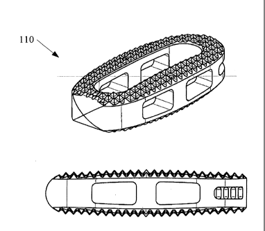
Fig. 11 illustrates a perspective view and a side view of a lumbar
spinal spacer including a porous material according to an embodiment of the
invention.
Fig. 12 illustrates a perspective view and a side view of another
lumbar spinal spacer including a porous material according to an embodiment of
the invention.
3
CA 02711403 2010-07-05
WO 2009/099559
PCT/US2009/000604
Fig. 13 illustrates a perspective view and a side view of another
lumbar spinal spacer including a porous material according to an embodiment of
the invention.
Fig. 14 illustrates a perspective view and a side view of another
lumbar spinal spacer including a porous material according to an embodiment of
the invention.
Fig. 15 illustrates a perspective view and a side view of another
lumbar spinal spacer including a porous material according to an embodiment of
the invention.
Fig. 16 illustrates a perspective view and a side view of another
lumbar spinal spacer including a porous material according to an embodiment of
the invention.
Fig. 17 illustrates a perspective view and a side view of another
lumbar spinal spacer including a porous material according to an embodiment of
the invention.
Fig. 18 illustrates a perspective view and a side view of another
lumbar spinal spacer including a porous material according to an embodiment of
the invention.
Fig. 19 illustrates a perspective view and a side view of another
lumbar spinal spacer including a porous material according to an embodiment of
the invention.
Fig. 20 illustrates a perspective view and a side view of another
lumbar spinal spacer including a porous material according to an embodiment of
the invention.
Fig. 21 illustrates a perspective view of a cervical spinal spacer
including a porous material according to an embodiment of the invention.
Fig. 22 illustrates a perspective view of another cervical spinal
spacer including a porous material according to an embodiment of the
invention.
Fig. 23 illustrates a perspective view of another cervical spinal
spacer including a porous material according to an embodiment of the
invention.
Fig. 24 illustrates a front perspective view of a porous lumbar
spacer according to an embodiment of the invention.
4
CA 02711403 2010-07-05
WO 2009/099559
PCT/US2009/000604
Figs. 25A and 25B illustrate a side plan view and a top plan view,
respectively, of a porous spacer according to an embodiment of the invention.
Fig. 26 illustrates a graph showing the relationship between the
compressive strength and the porosity of the spacer of Fig. 24.
Fig. 27 illustrates a graph showing the relationship between the
compressive strength of the spacer of Fig. 25A-25B.
Figs. 28A and 28B illustrate a front perspective views of sample
structures with solid cores according to an embodiment of the invention.
Fig. 29 illustrates a graph showing the differences between the
compressive moduli (stiffnesses) of various structures according to an
embodiment of the invention.
Fig. 30 illustrates a graph showing the ultimate compressive
strengths of various structures according to an embodiment of the invention.
DETAILED DESCRIPTION OF THE INVENTION
Numerous embodiments are described in this patent application,
and are presented for illustrative purposes only. The described embodiments
are
not, and are not intended to be, limiting in any sense. The presently
disclosed
invention(s) are widely applicable to numerous embodiments, as is readily
apparent from the disclosure. One of ordinary skill in the art will recognize
that
the disclosed invention(s) may be practiced with various modifications and
alterations, such as structural and chemical modifications. Although
particular
features of the disclosed invention(s) may be described with reference to one
or
more particular embodiments and/or drawings, it should be understood that such
features are not limited to usage in the one or more particular embodiments or
drawings with reference to which they are described, unless expressly
specified
otherwise.
The present disclosure is neither a literal description of all
embodiments nor a listing of features of the invention that must be present in
all
embodiments.
Neither the Title (set forth at the beginning of the first page of this
patent application) nor the Abstract (set forth at the end of this patent
5
CA 02711403 2010-07-05
WO 2009/099559
PCT/US2009/000604
application) is to be taken as limiting in any way as the scope of the
disclosed
invention(s).
In reference to Fig. 1 and Fig. 2, there is illustrated the difference
in final structure between a PEEK/r3-TCP, tricalcium phosphate, mixture and a
PEEK- only material placed in a 400 C furnace for 5 minutes. Specifically,
Fig.
1 shows PEEK granules that may be utilized to construct a porous spacer
according to embodiments described in more detail below. The granules of the
first preferred embodiment include a PEEK/beta-TCP mixture, having particles
within a size range of 0.5-1.0 mm, with TCP applied at 400 degrees Centigrade
for 5 minutes.
Inventive subject matter described herein relates to porous or
partially porous body composites used to manufacture devices such as spacers
for spinal fusion and tissue ingrowth surfaces in orthopedic devices, and to
methods for making and using the porous bodies.
In one embodiment, a method is shown for making a porous
intervertebral spacer usable in spinal fusion. The porous intervertebral
spacers
described herein include a main body made partially or totally of a composite.
In selected embodiments, a main body includes polyetheretherketone, particles
and a surface coating of beta tricalcium phosphate (13-TCP) covering at least
a
portion of the PEEK particles. Although PEEK is a polymer used in one
example the invention is not so limited. Other embodiments utilize various
thermoplastics other than or in addition to PEEK or combinations of polymers.
Porous spacer embodiments provide an initial stability and
ultimately allow bony ingrowth from an inferior and superior vertebrae. In
order
to have good vascularization and bony ingrowth, pore structure of a porous
spacer is generally interconnecting. In one example, a mean pore size as
measured with mercury porosimetry, and is preferably in a range of 100-500 m.
The range of 100-500 Am is not intended to be limiting and at least a portion
of
the pores may fall outside of this range. It is generally understood that to
allow
mammalian tissue ingrowth, the pores must be large enough to allow a vascular
network to be formed which at minimum requires passage of a red cell which is
6
CA 02711403 2010-07-05
WO 2009/099559
PCT/US2009/000604
approximately 5-10 m and thus this defines the desired lower size limit of at
least a portion of the pores. A broader range of pores could thus be 5-5000 m.
In one embodiment, a porous body formed using techniques
described in the present disclosure are further perfused with patients' bone
marrow and/or blood. The use of these autologous biologically active
substances can provide a source of cells and growth factors that can
accelerate
the formation of bone and tissue into and on the porous structure and can also
help to lead the precursor cells to differentiate down the desired path (i.e
stem
cells into osteoblasts that form bone). In one embodiment, the porous bodies
are
infused with allogenic biological substances to impart a similar effect. In
selected embodiments, biologically active substances such as growth factors
including, but not limited to BMP II, BMP VII and PDGF are infused. Synthetic
small molecules that stimulate bone or tissue formation are included in some
embodiments. Such small molecules include, but are not limited to, statins.
Although individual additive substances are recited above, combinations of
substances are also within the scope of the invention.
In some embodiments, the porous structure is modified to retain
these biologically active substances and release them over an extended period
of
time or direct the location of their release and activity. In some embodiments
the
porous structure is coated with a substance that holds and then releases an
active
substance over a desired period. The materials used in such a coating include
but are not limited to materials that hydrolytically degrade such as aliphatic
polyesters such as PLA and PGA and hydrogels such as PEG and CMC.
Alternately, in some embodiments the surface of the porous structures or
treatments provides the desired release kinetics. Such surface structures
include
microporosity and changing the surface wettability.
In other embodiments a biologically active substance is applied to
a separate carrier that is applied or inserted into the porous body of this
invention. In one embodiment, a separate carrier is pre-inserted into a porous
body. In one embodiment, a porous body is modified with areas of at least
partially reduced porosity to reduce or prevent the release of the
biologically
active substance in certain directions. In one example, a thin outer shell of
a
7
CA 02711403 2010-07-05
WO 2009/099559
PCT/US2009/000604
non-porous polymer or other material is placed on a porous core to prevent the
release of a biologically active substance in a radial direction. An advantage
of
such a configuration is realized in cervical fusion where the release of
growth
factors such as BMP II in a radial direction can lead to undesired tissue
growth.
In selected embodiments a non-porous material is made from a resorbable
material so that the directionally controlled release is time dependant.
In one example method, polymer particles that have a specific
particle size range are mixed with beta tricalcium phosphate (P-TCP), to form
a
mixture of polymer granules and coating powder. In one embodiment, the
mixing provides an at least partial coating of the 13-TCP around the surface
of the
polymer particles. Alternate materials that can be used to coat the polymer
include, but are not limited to, calcium powders, bone powder, hydroyapatite,
titanium (including titanium alloys and titanium oxides), barium salts and
zirconium oxide. The mixture is placed in one or more molds at a temperature
above a melting point of the polymer and held for a time effective to form
bonding at the contact points of melted polymer particles.
In selected embodiments the powder coating the surface the of the
polymer is subsequently removed and a microporous surface structure is
obtained, the mircopores resulting from the volume previously occupied by the
powder coating particles. An effective pore size of this microporous structure
is
in range of 0.1 and 100 microns.
In one example, the 13-TCP powder inhibits, slows or in some
embodiments, prevents the flow of polymer material above the melt temperature
and causes the polymer particles to bead. An end product is a continuously
porous material with a specific geometry that generally replicates the
geometry
of the mold. Examples of polymer material include, but are not limited to,
PEEK, carbon reinforced PEEK, PEKK, PAEK family, PEK PEKK, PEKEKK,
PCL, PLA, PGA, polyphenylene, self-reinforced polyphenylene,
polyphenylsulphone, polysulphone, PET, polyethylene, polyurethane or other
biocompatible polymers.
In some embodiments, additional materials are incorporated into
the porous body. In one embodiment, the polymer particles are fused throughout
8
CA 02711403 2010-07-05
WO 2009/099559
PCT/US2009/000604
a reinforcing structure. This reinforcing structure could be made from any
known biocompatible material including titanium and stainless steel or the
polymer itself and can provide additional mechanical strength to the porous
body. In another embodiment, radiopaque materials are incorporated to provide
selective areas of radiopacity so the location of the body can be visualized
with
X-rays or CT. These radiopaque materials include, but are not limited to,
biocompatible metals (e.g. titanium aluminum nitride (TAN), titanium aluminum
vanadium (TAV), tantalum, gold, barium, titanium, stainless steel), barium
sulfate, zirconium oxide and radiopaque dyes. In other embodiments, the
radiopaque material is used to mechanically reinforce the porous structure.
In some embodiments, the porous structure is selectively
compressed in selective areas to impart increased mechanical strength. This
compression is achieved through a combination of heat and and or pressure.
Methods to produce this heat and pressure include but are not limited to
ultrasonics, radio frequency heating, induction heating, lasers or direct
heating.
These areas of reinforcement may form features for engagement with an
instrument or structural ribs.
Exemplary Embodiments
Porous PEEK Method
One process embodiment creates porous intervertebral spaces.
The process embodiment includes using a polymer in particulate form. The
particle size is in a range of 0.25-1.0mm. This range is not intended to be
limiting and other particle sizes can be used. The particles are mixed with 1-
TCP at a ratio of 90% polymer 10% P-TCP. The particle size of P-TCP is in a
range of 0.01-0.1mm. The particles are placed in a container and are mixed
thoroughly. This mixing can be performed using a standard lab vortex shaker.
The shaking allows the smaller 13-TCP particles to at least partially cover
the
surface of the polymer particles. A sieve with a mesh size larger than p-TCP
particle size but smaller than polymer particle size is used to remove the
excess
P-TCP particles. The resulting powder mix includes polymer particles coated
with P-TCP. The purpose of the P-TCP is to prevent the polymer particles from
9
CA 02711403 2010-07-05
WO 2009/099559
PCT/US2009/000604
flowing freely when heated above melting point. The presence of p-TCP causes
the particles to bead and to prevent flow at or above melt point of the
polymer.
This allows for strong bonding between polymer particles while maintaining the
interstitial space. When cooled, the final material defines an interconnecting
porous polymer with P-TCP coating. The resulting material has the
interconnecting porous structure for boney ingrowth and a P-TCP coating to
produce a calcium rich surface for better osteoconduction.
As discussed above, in selected embodiment, the p-TCP or other
coating powder is later removed from exposed surfaces within pores via an acid
leaching, a selective solvent process, or another powder removal process. In
this
case the surface is calcium poor but has a microporous structure that can be
advantageous from a wettability and cellular attachment perspective.
Figure lA and 1B illustrate the difference in final structure
between a PEEK/P-TCP mixture and a PEEK- only material placed in a 400 C
furnace for 5 minutes. Figure 1A illustrates an interconnecting sample formed
using methods described above with P-TCP on the surface. The particle size and
the amount of the mixed particles inside the mold determine the porosity. The
final mold geometry determines the final porous component size and shape.
Figure 1B illustrates a collapsed structure of PEEK particles at
the same temperature and time where no coating particles such as 13-TCP were
used. As can be seen from the Figures, interstitial spaces are more greatly
preserved when coating particles such as P-TCP are included prior to melting
the
mixture. The process embodiments described herein allow for stronger bonding
compared to standard sintering methods at quicker processing time. Because
sintering involves heating the material below melt point, the bonding between
the particles is not as strong as materials bonded by heating the particles to
above melting point.
Figure 2 illustrates PEEK polymer particles coated with fl-TCP
powder by mixing 90% PEEK and 10% 0-TCP by weight prior to melting. The
mixture was placed in a 250 m sieve to remove the excess 13-TCP powder. The
resulting powder consisted of PEEK granules covered with13-TCP powder, as
shown in Figure 2.
CA 02711403 2010-07-05
WO 2009/099559
PCT/US2009/000604
Although a PEEK polymer coated with P-TCP powder is
described in the exemplary embodiment above, the invention is not so limited.
Other polymers coated with other power particles are within the scope of the
invention. One of ordinary skill in the art, having the benefit of the present
disclosure will recognize that with other polymers and other coating powders,
other processing conditions such as heating temperature and time, etc. can be
adjusted to form porous polymer structures using alternative materials.
Monolithic Porous Structure
One embodiment of the Porous PEEK structure is a prosthesis for
interverbral body fusion that is made completely of porous PEEK, as is shown
in
Figs. 3, 11, and 12A - 12B. The prostheses can assume the form of a variety of
external shapes in order to optimize endplate coverage. The superior and
inferior surfaces may include pyramidal or unidirectional teeth or ridges
molded
in order to increase the devices' primary stability in the intervertebral
space.
Some embodiments, one of which is as spacer 30 in Fig. 3, defines one or more
axial holes 32 to allow solid bony through growth. In one embodiment, lateral
windows in a side 34 of the spacer 30 are further provided to enhance the
assessment of fusion via radiograph or other suitable techniques. Although a
generally cylindrical shape is shown in Figure 3 as a monolithic porous
structure
example, other monolithic porous geometries such as solid cylinders, scaffold
shapes, complex molded custom fitted shapes, etc. are within the scope of the
invention.
Solid Core
Figures 4A, 4B and 4C illustrate an implant 40 for intervertebral
body fusion. The implant 40 is constructed of a solid PEEK core 42 thermally
bonded to porous endplates 44. This implant embodiment 40 serves to increase
the ultimate axial compressive strength of the implant while maintaining the
benefits of bony ingrowth and primary stability.
11
CA 02711403 2010-07-05
WO 2009/099559
PCT/US2009/000604
Figures 5A, 5B and 5C illustrate an implant embodiment 50 that
includes a porous PEEK main body 52 and a solid band 54, annularly positioned
about the main body 52.
Solid Implant Holder
During conventional implantation of an intervertebral body
device, it is desirable that a surgeon maintains precise control of the
implant.
One important part of such control is achieved by tightly gripping an implant.
It
is desirable for the steps of gripping and releasing to be such that an
introduction
profile of the spacer is not increased or otherwise changed in any significant
way.
In Figures 6A, 6B and 6C, an implant holding feature 62 is
integrated into a solid portion 64 of the implant embodiment 60 that is
mechanically connected to a porous component 66. An example of a mechanical
connection includes tabs 63 that fit into corresponding slots. Although tabs
63
are shown, other configurations of mechanical connections such as other
interference fit geometries, bayonette fasteners, etc. The embodiment of
Figures
6A, 6B and 6C shows the solid portion 64 extending from an inferior to the
superior surface of one side 68 of the implant which can be positioned to bear
the greatest axial loads and to increase a shear strength of the implant by
reinforcing the porous component 66.
In the embodiment show, the holding feature 62 includes a pair of
slots. In one embodiment a pair of slots such as slots 62 are configured to
interface with a surgeon's tool to provide precise control. One of ordinary
skill
in the art will recognize that a number of other possible holding feature
configurations such as single slots, protruding features, etc. are within the
scope
of the invention.
Figures 7A, 7B and 7C, illustrate another example of a holding
feature 72. In the example of Figures 7A-C, the holding feature 72 is
integrated
into a solid core 74 of the implant 70. Similar to embodiments described
above,
the implant 70 is composed of a solid portion 74 which includes the holding
12
CA 02711403 2010-07-05
WO 2009/099559
PCT/US2009/000604
feature 72, and a porous polymer portion 76 formed using methods described in
embodiments above.
Figure 10 illustrates another example embodiment 100 including
an implant holder feature 102 that is integrated into an exterior geometry of
a
solid portion 104 which is bonded to a porous body 106. As can be seen from
the examples, a number of possible configurations for implants and holding
features are contemplated.
Porous Endplate Feature on a Device for Disc Arthroplasty
Figure 8 illustrates one embodiment of an intervertebral
prosthesis for disc arthroplasty at 80 that includes porous PEEK endplates 82
thermally bonded to solid PEEK 84 with lateral insertion slots 86.
Multi-Component Constructs
Figures 9A, 9B and 9C illustrates one embodiment of an
intervertebral spacer 90 with integrated fixation showing porous PEEK
endplates
92 thermally bonded to a solid PEEK core 94 and mechanically connected to a
metallic plate 96. A central distractor slot aides insertion.
Spinal Spacer Example Configurations
Figures 11-20 illustrate a number of example configurations of
lumbar spinal spacers including at least a portion of porous polymer material
formed using methods described in the present disclosure. Although a number
of examples are shown, the invention is not so limited. In each example, the
entire spacer may be formed from porous polymer material as described, or only
a portion of the spacer may be formed from porous polymer material as
described. As described herein, other material configurations include a solid
portion bonded, mechanically joined, or otherwise attached to a porous
portion.
Example solid portions include solid cores, solid bands, solid skins, etc.
attached
to a porous polymer portion.
Figures 21-23 illustrate a number of example configurations of
cervical spinal spacers including at least a portion of porous polymer
material
13
CA 02711403 2010-07-05
WO 2009/099559
PCT/US2009/000604
formed using methods described in the present disclosure. Similar to
discussion
of lumbar spacers, a number of configurations utilizing porous polymer
materials
are within the scope of the invention. Configurations that utilize portions of
solid material as described above are also included.
Figure 11 shows a spacer 110 that includes at least a portion of
porous polymer material. Figure 12 shows a spacer 120 that includes at least a
portion of porous polymer material. Figure 13 shows a spacer 130 that includes
at least a portion of porous polymer material. Figure 14 shows a spacer 140
that
includes at least a portion of porous polymer material. Figure 15 shows a
spacer
150 that includes at least a portion of porous polymer material. Figure 16
shows
a spacer 160 that includes at least a portion of porous polymer material.
Figure
17 shows a spacer 170 that includes at least a portion of porous polymer
material.
Figure 18 shows a multi-component spacer 180 that includes at
least a portion of porous polymer material. A first portion 182, a second
portion
184, and a third portion 186 are shown attached together. In the embodiment
shown, the portions are attached using a mechanical attachment 188. In one
example, the mechanical attachment includes a dovetail configuration as shown
in the figure. Although a dovetail is an easy and effective mechanical
attachment, the invention is not so limited. Other geometries of mechanical
attachments 188 are within the scope of the invention.
Figure 19 shows a spacer 190 that includes at least a portion of
porous polymer material. Figure 20 shows a spacer 200 that includes at least a
portion of porous polymer material. Figure 21 shows a spacer 210 that includes
at least a portion of porous polymer material. Figure 22 shows a spacer 220
that
includes at least a portion of porous polymer material.
Figure 23 shows a multi-component spacer 230 that includes at
least a portion of porous polymer material. A first portion 234, and a second
portion 236 are shown attached together using a mechanical attachment 236.
Similar to spacer 180 described above, in one example the mechanical
attachment 236 includes a dovetail arrangement or similar mechanical
attachment.
14
CA 02711403 2010-07-05
WO 2009/099559
PCT/US2009/000604
Additional Surface Preparation
Embodiments described in the present disclosure can also include
various finishing processes depending on desired final properties. One
additional surface treatment includes using a plasma treatment with ionized
oxygen or other gas. In selected embodiments, such a plasma treatment alters
surface chemistry in a to increase wetability. Another surface treatment
includes
a Hydroxylapatite (HA) coating to increase an osteoconductive potential of the
implant surface. Another surface treatment includes a Calcium Phosphate
Coating to increase the osteoconductive potential of the implant surface.
Another surface treatment includes a titanium nitride coating to provide a
surface
desirable for bony ongrowth. Other surface treatments to provide a surface
desirable for bony ongrowth include titanium or other biocompatible metal or
oxide coatings applied by any of a number of processes such as physical vapor
deposition, chemical vapor deposition, etc.
Alternate Design Embodiments
Additional embodiments include an incorporation of larger,
discrete 13-TCP, titanium or other osteoconductive particles to the coating
powder mix. These larger osteoconductive particles are of approximately the
same size as the thermoplastic material. In selected embodiments, the discrete
osteoconductive particles enhance the osteoconduction properties of the porous
material already coated with 13-TCP powder. One source of osteoconductive
particles include CronOSTM manufactured by Synthes.
Alternate Applications
As noted above, other uses for the porous material include
scaffolds for tissue ingrowth applications other than spinal spacers. The
porous
material as described in embodiments above is further usable as a bone void
filler in a number of applications where bone ingrowth is desired in
anatomical
locations under physiological mechanical stresses. An example of an
application
other than a spinal spacer includes manufacturing at least part of an implant
suitable for use in cranial or craniofacial defect repair.
CA 02711403 2010-07-05
WO 2009/099559
PCT/US2009/000604
For applications other than those described in spinal spacer
examples above, it may be desirable to modify mechanical properties of the
porous polymer such as modulus, shear strength, etc. Changing the polymer
and/or coating powder results in different mechanical properties as desired.
In
selected embodiments, porous polymer structure properties are modified such
that they are suitable for soft tissue ingrowth.
Alternate Materials/Coatings
The main bodies, or portions thereof, of some of the spacer
embodiments of the present invention are formed from PEEK polymer or other
polymers. In addition to various polymer choices, coating powder materials can
be selected that are other than13-TCP. Alternative powders such as Barium
Sulfate (Ba504) or Strontium Carbonate (SrCO3) have similar effects on the
polymers during heating above the melt point as 13-TCP.
Mechanical Testing
In reference to Figs. 24 and 25A-25B, porous PEEK spacers were
created by placing the PEEK/O-TCP powder described above into a mold. The
amount of powder mixture placed inside the mold determined the porosity of the
final structure. The particle size range determined the pore size. Two types
of
samples with varying surface areas and heights were made to form spacers
similar in geometry to those known in the industry. The final samples were
tested for compressive strength. Fig. 26 illustrates a graph showing the
relationship between the compressive strength and the porosity of the spacer
of
Fig. 24, while Fig. 27 illustrates a graph showing the relationship between
the
compressive strength of the spacer of Fig. 25A-25B, having a 40 percent
porosity, and the height of the spacer.
In reference to Figures 28A-28B, composite samples, as opposed
to the fully porous samples, were made in which a solid PEEK cylinder was
sandwiched between two porous PEEK endcaps. The solid core gives the
composite it's higher compressive strength and the porous endcaps allow bone
ingrowth from top and bottom vertebrae. Fig. 29 is a graph showing the
16
CA 02711403 2010-07-05
WO 2009/099559
PCT/US2009/000604
differences between the compressive moduli (stiffnesses) of a spacer formed
entirely from porous PEEK, a spacer formed from solid PEEK spacer and having
porous PEEK endplates (such as the spacer illustrated in Figures 28A-28B), a
spacer formed entirely from solid PEEK, and a spacer formed entirely from
cancellous bone. Fig. 30 illustrates a graph showing the ultimate compressive
strengths of a spacer formed entirely from porous PEEK, a spacer formed from
solid PEEK and having porous PEEK endplates (such as the spacer illustrated in
Figures 28A-28B), and a spacer formed entirely from solid PEEK.
While a number of embodiments of the invention are described,
the above examples are not intended to be exhaustive. The foregoing
description
of the specific embodiments of the present invention have been described in
detail for purposes of illustration. In view of the descriptions and
illustrations,
others skilled in the art can, by applying, current knowledge, readily modify
and/or adapt the present invention for various applications without departing
from the basic concept of the present invention; and thus, such modifications
and/or adaptations are intended to be within the meaning and scope of the
appended claims.
17