Note: Descriptions are shown in the official language in which they were submitted.
CA 02711543 2011-03-18
-1-
ANTI-COGGING APPARATUS FOR PERMANENT
MAGNET ELECTRICAL MACHINES
TECHNICAL FIELD
The invention relates to permanent magnet electrical machines. More
specifically,
the invention relates to an apparatus for reducing the cogging torque in a
rotary
permanent magnet electrical machine.
BACKGROUND
The rotary permanent magnet (PM) electrical machines are known to suffer from
cogging torque. The cogging torque is an undesirable component of the torque
of a
PM machine and is caused by the interaction between the rotor permanent
magnets and the stator poles of the machine. It causes undesirable vibrations
of
the machine and it is particularly prominent on start up of the machine.
Several methods have been proposed for reducing the cogging torque in PM
machine. Those methods include :
- uniform or variable air gap thickness;
- phase shifting of the poles;
- skewing of the stator poles or of the rotor magnets; and
- use of fractional poles.
Most of the proposed methods used for reducing the cogging torque also reduce
the efficiency of the machine.
One proposed method for reducing the cogging torque of a PM machine is the
mechanical coupling of two machines, each machine having a stator with
electromagnets and a rotor with permanent magnets. The two machines are phase
shifted such that the cogging torques of the two machines cancel out. In such
a
CA 02711543 2011-03-18
-2-
dual machine, most of the critical components are doubled and the cost of the
machine is substantially increased.
SUMMARY
It is an aim of the present invention to provide an apparatus for reducing the
cogging torque of a rotary PM machine by generating an anti-cogging torque
that at
least partly cancels out the cogging torque of the rotary PM machine.
Cancellation of the cogging torque is provided by two sets of magnetic
elements,
one set being mechanically coupled to the stator and the other set being
mechanically coupled to the rotor of the PM machine. At least one of the two
set
comprises permanent magnets and the other set can comprise permanent magnets
or non-magnetized ferromagnetic materials such as soft iron. If the
arrangement of
the elements of the two sets is properly designed, magnetic attraction and
repulsion forces between the elements of the two sets as the machine operates
produce an anti-cogging torque that substantially cancels out the cogging
torque of
the machine.
One aspect of the invention provides An anti-cogging apparatus for
installation on a
permanent magnet electrical machine having a rotor, a stator and a cogging
torque,
said anti-cogging apparatus for reducing said cogging torque, said anti-
cogging
apparatus comprising: a first component mechanically coupled to one of said
rotor
and said stator and having a first set of elements of magnetic material
disposed
along a first circle; and a second component mechanically coupled to the other
one
of said rotor and said stator and having a second set of a plurality of
elements of
magnetic material disposed along a second circle coaxial with said first
circle, the
elements of said first set being uniformly arranged on the first circle with a
first
angular period and the elements of said second set being uniformly arranged on
the second circle with a second angular period, and with the first and second
sets
facing each other, with an air gap there between, for passive magnetic
interaction;
and wherein: at least one of said first and second sets has permanent magnets
for
CA 02711543 2011-03-18
-3-
generating an anti-cogging torque as a result of the passive magnetic
interaction
between said first and second sets, said anti-cogging torque having a
magnitude
substantially matching a magnitude of said cogging torque and a direction
opposite
to the direction of said cogging torque, thereby substantially canceling out
said
cogging torque, and said cogging torque has a main angular period component as
a function of a mechanical angle between the rotor and the stator, and said
main
angular period component is equal to a greatest common divisor of said first
angular period and said second angular period.
Another aspect of the invention provides a permanent magnet electrical machine
with reduced cogging torque, said machine comprising: a rotor with permanent
magnets; a stator, concentrically mounted to said rotor, for relative rotation
of said
rotor with respect to the stator thereby generating a cogging torque; a first
component mechanically coupled to one of said rotor and said stator and having
a
first set of elements of magnetic material disposed along a first circle; and
a second
component mechanically coupled to the other one of said rotor and said stator
and
having a second set of a plurality of elements of magnetic material disposed
along
a second circle coaxial with said first circle, the elements of said first set
being
uniformly arranged on the first circle with a first angular period and the
elements of
said second set being uniformly arranged on the second circle with a second
angular period, and with the first and second sets facing each other for
passive
magnetic interaction and with an air gap therebetween; and wherein : at least
one
of said first and second sets has permanent magnets for generating an anti-
cogging torque as a result of the passive magnetic interaction between said
first
and second sets, said anti-cogging torque having a magnitude substantially
matching a magnitude of said cogging torque and a direction opposite to the
direction of said cogging torque, thereby substantially canceling out said
cogging
torque, and said cogging torque has a main angular period component as a
function of a mechanical angle between the rotor and the stator, and said main
angular period component is equal to a greater common divisor of said first
angular
period and said second angular period.
CA 02711543 2011-03-18
-4-
Yet another aspect of the invention provides a method for reducing the cogging
torque of a permanent magnet machine, the method comprising the step of:
providing a permanent magnet machine having a rotor and a stator; determining
the cogging torque of the machine; providing a first component having a first
set of
elements of magnetic material disposed along a first circle, and a second
component having a second set of a plurality of elements of magnetic material
disposed along a second circle, the elements of said first set being uniformly
arranged on the first circle with a first angular period and the elements of
said
second set being uniformly arranged on the second circle with a second angular
period, wherein at least one of said first and second sets has permanent
magnets
for generating an anti-cogging torque as a result of passive magnetic
interaction
occurring between said first and second sets, said anti-cogging torque having
a
magnitude substantially matching the magnitude of said cogging torque and a
direction opposite to the direction of said cogging torque, thereby
substantially
canceling out said cogging torque, and said cogging torque has a main angular
period component as a function of a mechanical angle between the rotor and the
stator, and said main angular period component is equal to a greatest common
divisor of said first angular period and said second angular period; and
mechanically coupling one of the first and second components to the rotor and
mechanically coupling the other one of the first and second components to the
stator such that the first circle is coaxial with the second circle and the
said first set
faces the second set, with an air gap situated there between, for the magnetic
interaction.
BRIEF DESCRIPTION OF THE DRAWINGS
Further features and advantages of the present invention will become apparent
from the following detailed description, taken in combination with the
appended
drawings, in which:
CA 02711543 2011-03-18
-5-
Fig. 1 is an exploded perspective view of a rotary PM machine including an
anti-
cogging apparatus, according to an embodiment of the invention wherein the
anti-
cogging apparatus comprises two disks;
Fig. 2 is a longitudinal cross sectional view of the rotary PM machine of Fig.
1;
Fig. 3 comprises Fig. 3A and Fig. 3B, wherein Fig. 3A is a front view of the
disk that
is coupled to the rotor in the anti-cogging apparatus illustrated in Fig. 1
and Fig. 3B
is a back view of the disk that is coupled to the stator in the anti-cogging
apparatus
illustrated in Fig. 1;
Fig. 4 is an exploded perspective view of a rotary PM machine including an
anti-
cogging apparatus, according to another embodiment of the invention wherein
the
anti-cogging apparatus comprises two rings, one fitted within the other, each
having a set of magnetic elements, the two sets facing one another;
Fig. 5 comprises Fig. 5A and Fig. 5B, wherein Fig. 5A is a front view of the
disk that
is coupled to the rotor and Fig. 5B is a back view of the disk that is coupled
to the
stator in an anti-cogging apparatus, wherein each disk has thirty permanent
magnets distributed thereon;
Fig. 6 comprises Fig. 6A and Fig. 6B, wherein Fig. 6A is a front view of a
first disk
that is coupled to the rotor and Fig. 6B is a back view of a second disk that
is
coupled to the stator in an anti-cogging apparatus, wherein the front disk has
six
uniformly distributed permanent magnets and the second disk has five uniformly
distributed permanent magnets;
Fig. 7 comprises Fig. 7A and Fig. 7B, wherein Fig. 7A is a front view of the
disk that
is coupled to the rotor and Fig. 7B is a back view of the disk that is coupled
to the
stator in an anti-cogging apparatus, wherein each disk has thirty permanent
magnets distributed thereon and PM shape modifiers located on each side of
each
permanent magnets; and
CA 02711543 2011-03-18
-6-
Fig. 8 is a graph showing the effects of the PM shape modifiers of Fig. 6A and
Fig.
6B on the torque produced by the anti-cogging apparatus, wherein curve A shows
the shape of the cogging torque to be cancelled out, curve B shows the shape
of
the anti-cogging torque produced by an anti-cogging apparatus having no PM
shape modifier and curve C shows the shape of the anti-cogging torque produced
by an anti-cogging apparatus having PM shape modifiers and wherein curves A, B
and C are normalized in amplitude and curves B and C are sign-inverted for
better
visual comparison with the cogging torque.
It will be noted that throughout the appended drawings, like features are
identified
by like reference numerals.
DETAILED DESCRIPTION
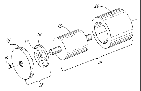
Now referring to the drawings, Fig. 1 and Fig. 2 illustrate a rotary PM
machine 10
along with an anti-cogging apparatus 12, according to an embodiment of the
invention. The PM machine 10 comprises a rotor 15 and a stator 20. In this
embodiment, the stator 20 is external to the rotor 15 but in other
embodiments, the
stator 20 could be internal to the rotor 15. An anti-cogging apparatus 12 is
installed
on the PM machine 10 for reducing its cogging torque. The anti-cogging
apparatus
12 comprises a first disk 16 having a first set of magnetic elements 17 (see
Fig. 3A)
and a second disk 21 having a second set of magnetic elements 23 (see Fig.
3B).
The magnetic elements of each set 17, 23 are circularly arranged about the
axis of
their respective disk 16, 21 with a space between each two successive elements
of
the set. Fig. 3A shows the first set of magnetic elements 17 on the first disk
16 and
Fig. 3B shows the second set of magnetic elements 23 on the second disk 21.
The
two disks 16, 21 are placed side-by-side such that the two sets of magnetic
elements 17, 23 face one another with an air gap 32 (shown in Fig. 2). In this
embodiment, the axes of the two disks 16, 21 are aligned on the axis of
rotation of
the PM machine 10, but the two disks 16, 21 could alternatively be misaligned
from
the PM machine 10 (using geared transmission for example) as long as one disk
16 is mechanically coupled to the rotor 15 and the other disk 21 is
mechanically
CA 02711543 2011-03-18
-7-
coupled to the stator 20 such that the rotation of the first disk 16 relative
to the
second disk 17 follows the rotation of the rotor 15 relative to the stator 20.
The two
disks 16, 17 are respectively affixed to the rotor 15 and the stator 20 using
bolts
and nuts, rivets, adhesive, or any other coupling means (not shown in the
figures).
In the embodiment of Fig. 1, the first set 17 is composed of six permanent
magnets
and the second set 23 of six soft iron elements. In this embodiment, the
permanent
magnets all have the same polarity facing the second set 23, i.e. the north
pole of
each permanent magnet faces the second set 23 (non-alternating permanent
magnets). This embodiment is adapted to cancel out a cogging torque having an
angular period of 60 as a function of the mechanical angle between the rotor
15
and the stator 20.
As the rotor 15 rotates, the first disk 16, which is mechanically coupled to
the rotor
15, follows and rotates relative to the second disk 21 which is mechanically
coupled
to the fixed stator 20. The soft iron elements 23 react in the magnetic field
of the
permanent magnets elements 17 and are attracted by the permanent magnet
elements 17. Since the set of permanent magnet elements 17 and the set of soft
iron elements 23 are periodically arranged respectively along the first disk
16 and
the second disk 21, the magnetic attraction force produces a torque that
varies as a
function of the angle between the rotor 15 and the stator 20. When the two
sets of
magnetic elements 17, 23 are phase shifted, the attraction force between the
two
sets 17, 23 produces a torque that tends to realign the two sets 17,23. When
the
two sets are aligned, the torque is null. An angularly variable torque is thus
provided and when the phase shift between the anti-cogging apparatus and the
PM
machine 10 is properly adjusted, the anti-cogging torque at least partly
cancels out
the cogging torque of the machine 10. The number of elements in each set of
magnetic elements 17, 23, their shape, their orientation and their position
are
adjusted such that the magnetic interaction between the first set of magnetic
elements 17 on the first disk 16 and the second set of magnetic elements 23 on
the
second disk 21 produces an anti-cogging torque having a magnitude as close as
possible to the magnitude of the cogging torque of the PM machine 10 but with
a
CA 02711543 2011-03-18
-8-
direction opposite to the direction of the cogging torque, thereby
substantially
canceling out the cogging torque of the PM machine 10.
It is noted that the first disk 16 and the second disk 21 could be
interchanged such
that the first disk 16 be coupled to the stator 20 and the second disk 21 be
coupled
to the rotor 15. This substitution would have no effect on the magnitude of
the
provided anti-cogging torque. One skilled in the art will appreciate that the
weight of
each set of magnetic elements 17, 23 should be considered in selecting which
disk
is to be coupled to the rotor 15.
Any PM machine 10 having a cogging torque, including motors and generators,
can
benefit from the present invention. For example, the PM machine 10 can be an
alternating current motor, a brushless direct current motor, a three-phase
electrical
generator, a transverse flux electrical generator, PM machines with phase
shifted
poles or skewed poles for reducing cogging torque, etc.
If the cogging torque to be cancelled out has a large amplitude, the soft iron
elements of the second set could be replaced by permanent magnets. In one
embodiment, the south poles of all the permanent magnets of the second set
face
the north poles of the permanent magnets of the first set. During operation of
the
PM machine 10, the elements of the first and the second sets are attracted and
the
angularly variable attractive force provides an anti-cogging torque.
In another embodiment, the north poles of all the permanent magnets of the
second set face the north poles of the permanent magnets of the first set. In
this
case, the angularly variable repulsion force of the magnets provides the anti-
cogging torque. It should be appreciated that a set of south-pole permanent
magnets could be inserted between the north-pole permanent magnets of the
first
set so that polarities would alternate along the disk. The number of permanent
magnets would then be doubled and the amplitude of the anti-cogging torque
would
be increased.
CA 02711543 2011-03-18
-9-
Similarly, if the cogging torque to be cancelled out has a rather small
amplitude,
whether the elements of the second set be soft iron elements or permanent
magnets, the number of elements of the second set can be reduced. For example,
in one embodiment, the second set is only composed of one permanent magnet
aligned with and facing one of the permanent magnets of the first set. The
angular
period of the anti-cogging torque (as a function of the angle between the
rotor and
the stator) is then the same as if the number of elements of the second set
would
be equal to the number of elements of the first set but the amplitude of the
produced anti-cogging torque is lower. The number of elements of the second
set
can be any divisor of the number of elements of the first set without
modifying the
angular period of the cogging torque.
Fig. 4 illustrates a rotary PM machine 10 along with an alternative
configuration of
the anti-cogging apparatus 35 which uses two concentric rings 40, 50 fitted
one
over the other and each bearing a set of magnetic elements 41, 51. The first
ring
41 is mechanically coupled to the rotor 15 of the PM machine 10 and the second
ring 50 is mechanically coupled to the stator 20. The two sets of magnetic
elements
41, 51 face one another for magnetic interaction, with an air gap
therebetween.
Fig. 5A and Fig. 5B respectively illustrate a first disk 52 and a second disk
53 of an
anti-cogging apparatus adapted to substantially cancel out the cogging torque
of a
transverse flux electrical generator having fifteen stator cores and fifteen
pairs of
rotor permanent magnets. The first disk 52 is to be coupled to the rotor and
the
second disk 53 is to be coupled to the stator of the generator. The cogging
torque
of the generator has a main period component of 12 . The first disk 52 and the
second disk 53 respectively comprise a first set 54 and a second set 55 of
thirty
circularly distributed permanent magnets. In each set 54, 55, the permanent
magnets are separated and have no direct contact with one another, i.e. they
are
angularly spaced by non magnetic material or air. The two disks 52, 53 are to
be
mounted such that the first set 54 faces the second set 55 with an in-between
air
gap. Both the first set 52 and the second set 53 comprise non-alternating
polarity
CA 02711543 2011-03-18
-10-
permanent magnets, i.e. all having the same polarity (the north pole) facing
the air
gap.
Generally, a suitable anti-cogging apparatus can be designed for any PM
machine.
In order to design a suitable configuration of magnetic elements, first, the
cogging
torque to be compensated is determined. The main period component of the
cogging torque can be easily determined since it is related to the number of
teeth
(m) on the stator, or the number of stator cores (m) in the case of a
transverse flux
machine, and to the number of pairs of magnets of circularly alternating
polarities
(n) on the rotor. The main period component can be generally calculated by
dividing rr by the least common multiple (LCM) of the number of stator
teeth/cores
(m) and the number of pairs of magnets of circularly alternating polarities on
the
rotor (n) (rr / LCM(m,n)). The exact variation of the cogging torque as a
function of
the relative angular position of the rotor to the stator can be measured using
an
appropriate method known by one skilled in the art. It can also be numerically
calculated using, for instance, finite element analysis or an analytical
solution.
The number of elements of the first set and of the second set of magnetic
elements
must be selected. The main angular period component of the anti-cogging torque
should be the same as the main angular period component of the cogging torque
to
be cancelled out. Generally, if the like magnetic elements in the first set
and the like
magnetic elements in the second set are uniformly spaced, the main angular
period
component of the anti-cogging torque is calculated by dividing 2rr by the
least
common multiple of the number of like magnetic elements in the first set (p)
and the
number of like magnetic elements in the second set (q) (2rr / LCM(p,q) ). For
the
purpose of this equation, soft iron elements are to be considered as like
elements
and permanent magnets having the same polarity facing the air gap are to be
considered as like elements. If the permanent magnets of one group alternate
in
polarity, p (or q) is the number of pairs of magnets.
For example, for a PM machine having fifteen teeth and fifteen pairs of
permanent
magnets, the main angular period component of the cogging torque is 12
(rr/15).
CA 02711543 2011-03-18
-11-
Fig. 6A and 6B illustrates one suitable design of an anti-cogging apparatus
for
reducing the cogging torque of such a PM machine. The anti-cogging apparatus
has a first set 56 of six uniformly spaced non-alternating permanent magnets
54
and a second set 57 of five uniformly spaced non-alternating permanent magnets
55. Another suitable design of an anti-cogging apparatus has a first set of
thirty
non-alternating polarity and uniformly spaced permanent magnets and a second
set of two uniformly spaced soft iron elements. Yet another suitable design
has a
first set of thirty uniformly spaced non-alternating permanent magnets and a
second set of thirty uniformly spaced non-alternating permanent magnets. Still
another suitable design has a first set of sixty uniformly spaced alternating
polarity
permanent magnets and a second set of sixty uniformly spaced alternating
permanent magnets.
In alternative embodiments, the number of magnetic elements in the first set
is
selected such that the angular period (2rr/p) of the arrangement of the first
set
matches the main angular period component of the cogging torque. The second
set
may have a number q equal to p of uniformly spaced like magnetic elements, or
one or more elements of the second set may be omitted while the other elements
remain at their original position. Accordingly, the number of like magnetic
elements
of the second set is any positive integer no greater than p and the like
magnetic
elements are located on selected ones of p uniformly spaced positions. In
other
words, the spacing between two consecutive magnetic elements in the second set
is a multiple of the first angular period (2rr/p). For instance, according to
the above
described example where a PM machine has fifteen teeth and fifteen pairs of
permanent magnets, the angular period (2n/p) of the arrangement of the first
set is
12 and the number of uniformly spaced like magnetic elements in the first set
is
thirty. The second set may have a number q of thirty uniformly spaced like
magnetic elements or one to twenty-nine elements may be omitted while the
other
elements remains at their original position.
The amplitude of the anti-cogging torque can be matched to the amplitude of
the
cogging torque by varying the number of magnetic elements in the first and the
CA 02711543 2011-03-18
-12-
second set. For example, for a main angular period component of the cogging
torque to be cancelled out of 12 (rr/15), one suitable first set is composed
of thirty
non-alternating polarity permanent magnets. The second set can then be
composed of only one permanent magnet but the amplitude of the produced torque
may then be too weak to cancel out the cogging torque of the PM machine. As
described above, the number of permanent magnets in the second set can be
increased to up to thirty, depending on the amplitude of the cogging torque to
be
cancelled out. Additionally, the radial position of the two sets can be varied
to
match the amplitude of the anti-cogging torque to the cogging torque to be
cancelled out.
It should be noted that the variation of the magnitude of the cogging torque
as a
function of the angular position can be more complex. For a better cogging
torque
cancellation, the magnitude of the anti-cogging torque as a function of the
angular
position should be matched to the magnitude of the cogging torque (same
magnitude but opposite direction). In order to adjust the angular variation of
the
magnitude of the anti-cogging torque, the shape of the magnetic elements can
be
tweaked. Trial and error, analytical and finite element resolution methods can
be
used for this purpose.
One embodiment wherein the magnitude of the anti-cogging torque is adjusted by
modifying the shape of the magnetic elements is shown in Fig. 7A and Fig. 7B.
This
embodiment is equivalent to the embodiment illustrated in Fig. 5A and 5B but
the
shape of the permanent magnets of both the first set 54 and the second set 55
is
tweaked by providing PM shape modifiers 60. Fig. 7A shows the first disk 58
that is
coupled to the rotor and Fig. 7B shows the second disk 59 that is coupled to
the
stator of the PM machine. As in the embodiment of Fig. 5A and Fig. 513, this
embodiment is adapted for a transverse flux electrical generator having
fifteen
stator cores and fifteen pairs of rotor permanent magnets. The PM shape
modifiers
60 are pieces of non-magnetized magnetic material such as soft iron pieces.
One
PM shape modifier 60 is placed on each side of each permanent magnet. In the
illustrated embodiment, each permanent magnet is rectangular and has its
longest
CA 02711543 2011-03-18
-13-
length along the radius of the anti-cogging apparatus. Each PM shape modifier
60
is also rectangular and its longest length is about half of the longest length
of the
permanent magnets. The PM shape modifiers 60 are juxtaposed to the radially
external half of the permanent magnets and on each of their sides. The
addition of
the PM shape modifiers 60 results in an angular widening of the permanent
magnets on their radially external half. The resultant modified permanent
magnet
has a "T"-shape and the resultant modified permanent magnets still have no
direct
contact with one another.
Fig. 8 is a graph showing the effect of the PM shape modifiers shown in Fig.
7A
and Fig. 7B on the torque produced by the anti-cogging apparatus, by comparing
it
to the torque produced by the anti-cogging apparatus illustrated in Fig. 5A
and
Fig. 5B and having no PM shape modifier. Curve A shows the shape of the
cogging
torque to be cancelled out as a function of the angular position of the
generator (the
torque as shown is normalized in amplitude). Curve B shows the shape of the
anti-
cogging torque produced by the anti-cogging apparatus illustrated in Fig. 5A
and
Fig. 5B and having no PM shape modifiers, as a function of the angular
position
(the torque is normalized in amplitude and sign-inverted for better visual
comparison with the cogging torque). One should appreciate that the match
between curve A and curve B is not perfect and that the anti-cogging torque
shown
in curve B does not fully, but still substantially does, cancel out the
cogging torque
of the generator. Curve C shows the shape of the anti-cogging torque produced
by
the anti-cogging apparatus illustrated in Fig. 7A and Fig. 7B and having PM
shape
modifiers, as a function of the angular position (as for curve B, the torque
is
normalized in amplitude and sign-inverted). Compared to the anti-cogging
torque of
curve B, the anti-cogging torque of curve C better matches the shape of
cogging
torque of the generator as a function of the angular position of the
generator.
It should be appreciated that the configuration of the PM shape modifiers 60
illustrated in Fig. 7A and Fig. 7B and described herein is given as an example
and
that any shape of magnetic element could be designed or chosen by trial and
error
so that the anti-cogging torque cancels out with the best possible match the
CA 02711543 2011-03-18
-14-
cogging torque of a given PM machine. For example, a resultant shape of a
magnetic element could be a cross, a "V" or any other shape.
It is noted that, since the magnetic elements are passive ones, such as
permanent
magnets and other ferromagnetic materials, the interaction between the two
sets of
magnetic elements is passive as opposed to, for instance, the active
interaction
between electromagnets and permanent magnets, which uses an external energy
source and control to provide electrical current to the coils of the
electromagnets to
magnetize its ferromagnetic core.
Multiple pairs of sets of magnetic elements could be used in the anti-cogging
apparatus in order to fine tune the magnitude of the anti-cogging torque to
match
the one of the cogging torque. For example, one pair of sets of magnetic
elements
could be used for canceling out the cogging torque associated with each phase
of a
three-phase machine.
Magnetic elements could be uniformly or non-uniformly disposed in a circular
array,
magnetic elements could be phase shifted or magnetic elements of the same set
could be radially misaligned in order to modify the magnitude of the anti-
cogging
torque as a function of the angular position in order better match the
magnitude of
the cogging torque of the PM machine.
It is also noted that while in the illustrated embodiments one of the two
poles of
each permanent magnet faces the air gap between the first and the second set
of
magnetic elements, each permanent magnet could alternatively be disposed such
that its both poles are to be adjacent to the air gap, each permanent magnet
thereby providing two magnetic poles alternating along the disk or the tube.
The embodiments of the invention described above are intended to be exemplary
only. The scope of the invention is therefore intended to be limited solely by
the
scope of the appended claims.