Note: Descriptions are shown in the official language in which they were submitted.
CA 02711551 2010-07-07
PCT/DE2008/000 909
DESCRIPTION
CATALYTIC ACTIVE COATING OF CERAMIC HONEYCOMB BODIES, METAL
SURFACES AND OTHER CATALYST CARRIERS FOR WASTE AIR
PURIFICATION SYSTEMS AND BURNER SYSTEMS
The device described in the present patent application is
an active coating, and the method described is a method for
using the active coating. Both the method and the device
are described.
The object of the invention is to improve the purification
of waste air and combustion in two stages by ensuring
flameless catalytic gasification with intermediate cooling
and flameless catalytic combustion of the gasification
gases on catalytic surfaces for the purpose of reducing
pollutants in the waste gases, thereby reducing consumption
and at the same time minimising production of nitrogen
oxides and combustible residual gases such as CO and
hydrocarbons.
In this context, the underlying idea is inspired by the
hypothesis that it is possible to improve the properties of
waste air purification and combustion significantly if a
catalyst is able to be used so that the oxidation reactions
of the fuel may take place at lower temperatures on stable
catalytic surfaces, evenly over large temperature ranges
and completely until extremely small quantities of residue
are left.
A device for catalytic purification of waste air containing
hydrocarbons is described in patent application PA 198 00
420.6 "Compact system for catalytically purifying waste air
from furnaces".
In that system, Catalytic honeycomb bodies in a sheet steel
housing are preheated with electric heating rods until they
CA 02711551 2010-07-07
- 2
are able to trigger a reaction between the hydrocarbon-
containing air that is passed through them and the surface
of the honeycomb bodies, causing the hydrocarbons to be
oxidised to water vapour and carboxylic acid, thereby
purifying the air.
In that application, an innovative catalyst uses the
constituents cobalt, cerium and lanthanum to achieve
vigorous activity through crystal formation. This enables
the platinum component to be significantly reduced and
results in a purification effect in the temperature range
between 300 and 600 C.
It has now been found that this invention suffers from a
number of drawbacks, which the new technology is designed
to overcome. These drawbacks are the abatement of activity
at temperatures only slightly above the reaction
temperature range, due to the wash coat, which cannot
withstand temperatures higher than 600 C, reduced adhesion
of the catalytic layer to the surface, so that the coat is
stripped off when exposed to higher flow speeds, and the
configuration of the device, which only allows cold gages
to be fed in but is not suitable for connecting a
downstream device for burner systems.
Burners, which are also used in thermal waste air
purification systems, as also suitable for downstream
connection to catalytic systems as well, in which case they
are operated at reduced power. In this context, however, in
contrast to the property described in PA 198 00 420.6, they
must also possess the property that the catalytic layer is
able to withstand considerably higher temperatures, flow
speeds, and mechanical stresses. This is not possible with
the coating described in PA 198 00 420.6.
A temperature limitation is imposed not least by the use of
molecularly fine aluminium oxide, condea, whose use is
CA 02711551 2010-07-07
- 3 -
essential to provide the greater surface area necessary for
the catalytic technique.
This aluminium oxide component loses its structure at
600 C, and as a result the catalytic layer on top of it
becomes detached. The same thing happens at higher flow
speeds and under the impact of fine particles that are
swept along with the flow.
These drawbacks also render the catalytic coatings
unsuitable for the catalysts made from cobalt, cerium and
lanthanum in this form of the coating. While it is true
that they have comparable catalytic properties to the
platinum in the form described in patent application 198 00
420.6, yet, like platinum, they are not suitable for the
catalytic postreaction in thermal air puxifacation plants.
Surprisingly, it has been found that there is a way to
eliminate all of these drawbacks. The key in the invention
consists in a new coating technique, and in a consequential
new use of these catalysts, coated in this manner by this
new coating technique, in the air purification and burner
technique.
It was discovered completely unexpectedly that precoatings
with precious metal powder having a grain size smaller than
}gym are capable of providing the firm basis, thermst.
stability and a sufficient surface for the subsequent
coating of the lanthanum, cerium and cobalt crystal to
enable a catalytic reaction to begin at low temperature
(figure 1). In this regard, it has proven particularly
advantageous if the metal powder precoating is carried out
with a sugar solution.
It was not previously known that alloys of metal and
pZQ-Cious metal powder form an ideal, abrasion resistant
base for the catalytic coating (figure 2). At the same
CA 02711551 2010-07-07
- q
time, the application field for the catalyst is extended
beyond 600 C and up to 1000 C.
The temperature-sensitive surface enlargers consisting of
aluminium oxide (condea) that were essential in the past
are completely replace and are no longer needed.
The activity of the catalyst was not even reduced by
blowing out with compressed air (> 50m/s). The metal-coated
catalyst was able to withstand temperature peaks of 1100 C
without measurable loss of activity (figure 3 / diagram 2).
Repeated continuous loads of 550 C are tolerated by the new
catalyst with no loss of performance.
Total loss of catalyst activity was not observed until
temperatures >1200 C. Accordingly, the coatings according
to the invention are also suitable for subsequent use
downstream of thermal waste air purification plants in this
form. Also in this form, they help to reduce fuel
consumption because they enable the burner temperature to
be lowered by 5o - 70%.
An example of the device according to the invention is the
coating of honeycomb bodies. The honeycomb bodies are dried
by heating to 200 C. After cooling, they are immersed in a
suspension of sugar solution with precious metal powder
having a grain size < 10 um, wherein one honeycomb body of
size 150 mm x 150 mm x 150 mm is able to hold between 500
and 1,000 g metal power, in other words each litre volume
of catalyst maintains from 150 to 300 g metal powder
distributed evenly on the surface of the honeycomb bodies
and their channels.
The honeycomb bodies are then calcined to form a solid
coating by heating them rapidly to 800 to 10000C within 1-2
hours in the furnace, together with the suspension. After
CA 02711551 2010-07-07
55 -
the honeycomb body has been allowed to cool, they are then
immersed in an aqueous bath containing lanthanum-cerium-
cobaltite and oxal.;.c acid.
In this context, a quantity of 37-185 g per honeycomb body,
that is to say 10 to 50 g/litre of the lanthanum-cerium-
cobaltite crystal powder, is spread over the aqueous
solution. The soaked honeycomb body is then burned at a
temperature from 500-8006C, and is then ready for use.
The figures shown in the following explain the method and
the device according to the invention with reference to the
images of the coating and of the effects of the catalysts
in the conversion of hydrocarbons into the gases C02 and
H20.
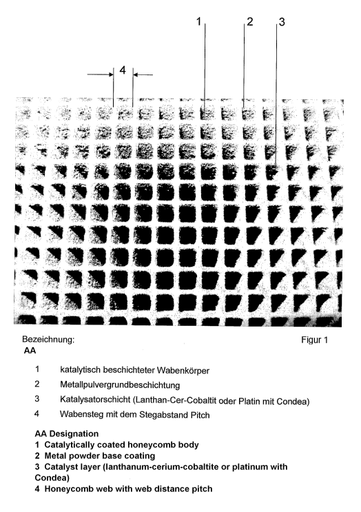
Figure 1 shows the image of doubly coated catalyst 1. The
non-homogeneous surface of stainless steel coating 2 is
clearly evident. The non-homogeneous surface is evidence of
the second coating with lanthanum-cerium-cobaltite crystals
3. Coating takes place in a honeycomb structure having a
web spacing 4, also called the pitch.
In order to explain the production of the coating in
greater detail, figure 2 shows a magnified image of the
surface of the honeycomb body with the same elements,
wherein the surface has only been coated with the metal
powder and burned. Since the two figures are different view
of the same body, the same reference numbers are used to
refer to the same items in both. The application of the
lanthanum -cerium -cobalt ite powder in aqueous solution with
oxalic acid as a binding agent is the second step in the
coating.
The result of the second coating is evident in figure 3,
which shows the finished catalyst body in use. The
hydrocarbon component of the gas passing through this body
CA 02711551 2010-07-07
triggers a flameless increase in temperature due to the
oxidation reaction, which becomes visible when the catalyst
body begins to glow at 900 C.
Figure 4 shows the mode of operation of the catalytic
coating. T1 designates the temperature of the hydrocarbon-
air mixture at the inlet.
T2 indicates the temperature that is reached at the inlet
to the catalyst. T3 designates the temperature farther back
in the honeycomb body. This is lower because heating the
ceramic consumes some of the heat energy, thus lowering the
temperature. T4 represents room temperature, which is below
the horizontal axis of the diagram. T5 indicates the
temperature scale, and T6 refers to the time scale.
Figure 5 shows another plot of these parameters from a
technical application. Here too, the same reference numbers
are used as. in figure 4. Ti indicates the inlet
temperature, T2 the temperature at the catalyst inlet, T3
the temperature farther back in the catalyst, and T4 the
temperature at the end of the technical device. T5 refers
to the temperature scale and T6 designates the time scale.
Figures 4 and 5 shows that the device according to the
invention has a significantly expanded application range.
Temperature fluctuations up to more than lo00 C and gas
flow speeds of up to 5 m/s over the catalytic surface are
tolerated with no loss of activity, and the catalytic
coating functions in the same way as before.
The effect of the heat dissipation by the underlying metal
coating has a powerfully stabilising influence on the
catalytic activity. Without this coating according to the
invention, the same active substances, such as platinum and
lanthanum-cerium -cobalt ite, are not able to withstand such
temperatures, instead they suffer equal or even greater
CA 02711551 2010-07-07
- 7
damage than those with the coating according to the
invention, but at temperatures 400 C lower.
The method will be explained with a description of 3
practical cases of use of these coated honeycomb bodies.
A flamelees catalytic firing chamber in a condensing boiler
includes in sequence the igniter, the gasification catalyst
layer in the form of metal honeycombs, ceramic honeycombs
and/or metal meshes, the heat exchanger 1, the mixing
chamber for the gasification gases and secondary air, and
the combustion catalyst layer, with heat exchangers
downstream.
In this way, a flame is not required. The volume of the
condensing boiler may be smaller since a flame is not
required. The exhaust gas values achieved with this
catalytic combustion are only a fraction of those for flame
combustion, that is to say catalytic combustion is
extremely clean.
A further embodiment of the method is catalytic post--
purification in thermal waste gas purification processes.
when a honeycomb catalyst layer is arranged after the
burner for thermal waste air purification, the process may
be carried out using the burners at a fraction of their
capacity, since the layer is fully active starting from an
average temperature of 3540C. An average temperature of
450OC-6000C is optimal.
The catalytically coated honeycombs retrofitted in thermal
burner systems are installed as segments and bolted to the
Corners of the honeycomb bodies. The honeycombs, which are
adapted to the round cross-section, have a metal outside
frame, which is affixed to the outer pipe by a threaded
connection. This outside frame transfers the support to the
CA 02711551 2010-07-07
8
inner honeycombs via the bolts in the corners of the
honeycomb.
In a third embodiment of the method for using the coating,
it is applied to a fuel cell. The metal power coat applied
to the fuel cell membrane not only assures adhesion, it
also serves to increase the surface area and fulfils the
function of current drain.
The lanthanum-cerium-cobaltite layer not only replaces the
platinum coating completely, it also enables a
significantly longer service life. Depending on the field
of application and the temperature range, this service life
factor is in the order of 5-100, that is to say the layer
retains its activity for a period that is longer by this
factor.
The invention will now be explained in greater detail with
reference to special operational examples for the coating
device and the method of the application in the fields of
burner technology, retrofitting thermal waste air
purification systems and fuel cells.
In a first application example, a condensing boiler with a
thermal output of 18 kW has a ball distribution nozzle that
uses compressed air to distribute 1.5 kg heater oil via a
rotating, grooved distribution ball evenly in an air volume
of 12 m3/h and converts it to a fuel gas in a ceramic
honeycomb of the type shown in figure 1. No flame Is
produced, instead the conversion takes place in the
flameless catalytic manner as described in figure 3, on the
surface according to the invention,
Water flows through the heat exchanger that is arranged
thereafter, and the beat is transferred first to the heat
reservoir, the residual heat going to the heating circuit.
In giving off heat in the heat exchanger, the gasification
CA 02711551 2010-07-07
gases cool to temperatures below 300 C. The heat exchanger
is made from stainless steel to resist corrosion by CO.
In the subsequent mixing chamber with tangential injection
of the secondary air, which is preheated in the heat
exchanger at the end of boiler and with the downstream
mixer, a Venturi mixer manufactured by Sulzer, a
gasification gas/air mixture with :Lambda close to 1.0 is
created via the secondary 12 m3/h.
In this way, the exhaust gases may be reduced in terms of
both the. nitrogen oxides and the air via a three-way
catalytic converter, similar to the low values in an
automobile.
In this context, the more sulphur-resistant mode of
operation of the catalytic converter according to the
invention also has distinct advantages over the
conventional automobile catalytic converter. It brings the
temperature of the combustion mixture to the optimum
temperature of 800 C, which enables heat to be drawn off in
the downstream heat exchangers for the heating circuit and
hot water during peak consumption times.
In a second application example, retrofitting of a thermal
waste air purification system with the honeycomb bodies
according to the invention is described. For this, the
temperature of the thermal waste air purification system is
lowered from an operating temperature of 900 C to an
operating temperature of 500 C by reducing the quantity of
fuel, natural gas or heating oil introduced. An
intermediate chamber for the catalytic honeycomb bodies is
created in the round firing chamber.
This intermediate chamber consists of a honeycomb retaining
ring having an annular gap of 155 mm, into which the four
honeycomb sections are inserted like four slices of a cake.
CA 02711551 2010-07-07
The honeycomb sections are manufactured from a porous
honeycomb ceramic with 150 x 1SO x 150 mm honeycombs having
a pitch of 4 mm.
They are conformed to the geometry of the quarter-circle,
coated in accordance with the invention, and bolted to each
other in the corners of the honeycomb bodies via threaded
rods with washers on both sides. In this way, the retaining
force of the ring on the pipe is transferred via the mutual
bracing of the ceramic elements as far as the innermost
honeycomb body, so that it cannot be blown out of the
structure, since it is held in place via the outer ring and
the threaded rods.
The effect of the catalytic disc may be seen in figure 3.
In order to guarantee that the limit values are maintained,
a second honeycomb layer is provided. This is attached
securely to a second outer ring in the catalyst chamber.
The two layers are installed in the catalyst chamber from
both sides of the pipe, which is then flange-mounted on the
burner chamber. A diffuser disc with baffles is arranged at
the end of the burner chamber to completely prevent the
radiation of the flame from affecting catalyst, thereby
ensuring the catalytic layers will have a long service
life.
In a third application example, the use of the inventive
use of the catalytic coating in a fuel cell is described.
In this example, the coating according to the invention is
exceptionally effective, since it also significantly
improves the current drain from the membranes via the metal
powder surface.
An aluminium fibre fuel cell membrane is furnished on both
sides with the coating according to the invention and
inserted in a fuel cell for the fuels hydrogen, methane,
methanol, ethanol, and gas-phase hydrocarbons on one side
CA 02711551 2010-07-07
li.
and air on the other side. in this context, the potential
of the coating for converting and gasifying hydrocarbons
with the coating according to the invention is a further
advantage.
The membrane is produced with dimensions 150 x 150 mm,
coated, and equipped with the corresponding gas ducts
distributed evenly in the frame. in this case, the inlets
are connected alternatingly to the fuel side and the air
side. The fuel plates are wired in the same way as for
conventional fuel cells.
The effect of the coating according to the invention
consists in significantly improved effectiveness due to the
lower electrical resistances in the catalytic coating, in
the current drain, and considerably extended service life.
The coating requires no platinum, even in the case of fuel
cells that have originally been designed for platinum
coating. The coating has equivalent properties to those of
the platinum coating but with lower conduction resistance,
lower sensitivity to contamination, and a significantly
longer service life due to the greater stability of the
crystals of coating according to the invention compared
with the platinum flake coating.