Note: Descriptions are shown in the official language in which they were submitted.
CA 02711745 2010-07-08
WO 2009/050478
PCT/GB2008/003522
1
Catheter Apparatus
This invention relates to catheter apparatus, particularly, but not
necessarily exclusively,
catheter apparatus for the treatment of chronic total occlusions.
A chronic total occlusion (CTO) is a blockage in a blood vessel, which is
typically more than
three months old, formed due to the build up of atherosclerotic plaque in the
blood vessel
wall, narrowing the path through the blood vessel and ultimately closing it
off, preventing
blood flow through the vessel.
Patient's with CTOs suffer symptoms such as angina and myocardial infarction,
leading to a
high level of morbidity. If a CTO is reopened there is known to be a benefit
in terms of
reduced morbidity and mortality.
Currently, coronary artery bypass graft (CABG) surgery is the preferred
treatment of a CTO,
which works by establishing blood flow round the CTO. However, bypass surgery
is
invasive, complex, expensive and not without risk to the patient. In view of
this, in some
cases, percutaneous transluminal coronary angioplasty (PTCA) are employed.
CA 02711745 2010-07-08
WO 2009/050478
PCT/GB2008/003522
2
Typically, PTCAs involve specialist guidewire exchange at the CTO site. For
example, a
guide catheter is sent to the proximal part of the coronary artery, and a
stiff guidewire is then
passed down the catheter towards the CTO. The wire is then used to probe the
calcified cap
of the CTO to either find a pathway, such as a microvessel, through the CTO,
or penetrate
the cap of the CTO and allow a new pathway through the CTO to be established.
Once the thin guidewire has successfully crossed the CTO, a balloon catheter
is passed
along the guiding wire and through the CTO. The inserted balloon is then
inflated, crushing
the calcification and plaque against the vessel wall. A stent can then be
inserted into the
open vessel and expanded in an attempt to ensure the vessel remains open.
Known devices employing guidewires for the treatment of CTO's include the
"Conquest"
device by Asahi Intecc Co., Ltd. and the "CrosswireTm" device by Terumo
Medical
Corportation. These devices employ stiff guidewires to increase the
pushability of the
guidewires to facilitate crossing of the CTO; however, the increased stiffness
limits the ability
of the wire to find an appropriate path through the CTO, and because of their
stiffness may
of themselves cause complications.
Other known guidewires employ microcatheters to stabilize guidewires. For
example,
microcatheters are used in Ev3 Inc.'s "Echelonn1", Boston Scientific
"Excelsior " and St.
Jude Medical, Inc.'s "Venture'", relating to US2005/0209559. Abbott
Laboratory's "Asahi
Tornuse" is a modified guide wire.
Microcatheters add support to the wire. However, with the exception of St.
Jude Medical,
Inc.'s "Venture", they do not allow, in situ, any alteration in the direction
of travel of the
guide wire, meaning that it is difficult to probe different areas of the CTO
with the guidewire
in order to find an appropriate path through the CTO.
CA 02711745 2010-07-08
WO 2009/050478
PCT/GB2008/003522
3
St. Jude Medical, Inc.'s "Venture'" has a microcatheter which uses wires
embedded in the
catheter which can be pushed and pulled in order to steer the tip of the
catheter, and thus a
guidewire extending through the catheter. However, it has been found that the
response of
the catheter tip to steering can be difficult to predict.
Alternative known devices for treating CTOs include Lumend Inc.'s Frontrunner
device,
relating to US2005/0222595, which uses expansion tongs to break up the CTO via
blunt
microdissection. However, this device is complicated and expensive, and may
cause
dissection of the blood vessel wall, potentially leading to vessel rupture.
FlowCardia Inc's CrosserTM device, relating to US6942677, is used to re-
canalize CTOs and
relies on a monorail catheter delivering vibrational energy to facilitate the
crossing of CTOs.
Although considered less traumatic than the Frontrunner , it suffers similar
problems, and
relies on an expensive control system.
IntraLuminal Therapeutics, Inc.'s Safe-Cross device, relating to US6852109,
uses optical
coherence reflectometry which provides information on the cap of the CTO, to
enable the
user to probe the guidewire at an optimal area of the CTO. However, this
device has been
found to be difficult to use and expensive_
According to a first aspect of the present invention, there is provided a
catheter apparatus,
the catheter apparatus having a proximal end and a distal end, the distal end
being for
insertion into a patient's body, the catheter apparatus comprising:
a catheter having a proximal end and a distal end;
first and second lumens for accommodating first and second guidewires
respectively,
each lumen comprising a distal opening, the distal openings of the first and
second lumens
being moveable relative to each other; and
CA 02711745 2010-07-08
WO 2009/050478
PCT/GB2008/003522
4
an actuator for controllably changing the separation between the distal
openings of
the first and second lumens.
One or both of the first and second lumens may be provided within the
catheter, whereupon
the distal openings of the first and/or second lumens are preferably provided
at the distal end
of the catheter. As an alternative, the apparatus may comprise an additional
section, e.g., a
tube, in which one of the first and second lumens is provided. This may
provide what is
known as a 'rapid exchange lumen'. The additional section is preferably fixed
to the
catheter, and may extend alongside the catheter from a position at the distal
end of the
catheter, along all or part of the length of the catheter.
Since the actuator can change the separation between the distal openings, the
separation
between the first and second guidewires, which can project from the distal
openings, can
also be changed accordingly.
According to a second aspect of the present invention, there is provided a
catheter
apparatus, the catheter apparatus having a proximal end and a distal end, the
distal end
being for insertion into a patient's body, the catheter apparatus comprising:
a catheter having a proximal end and a distal end;
first and second guidewires, the guidewires arranged to project at the distal
end of
the catheter apparatus, and
an actuator for controllably changing the separation between the guidewires at
the
distal end of the catheter apparatus.
Preferably, the first and second guidewires are disposed in first and second
lumen, which
may be arranged as described above with respect to the first aspect of the
invention.
CA 02711745 2010-07-08
WO 2009/050478
PCT/GB2008/003522
In the first and second aspects, preferably the first guide wire is an
introducer guidewire for
guiding the apparatus to a destination in the patient's body and preferably
the second guide
wire is a work wire for probing and passing through an occlusion, e.g. a CTO,
in a blood
vessel. Since the separation between the second guide wire and the first
guidewire can be
5 adjusted, the second guidewire can probe different areas of the calcified
cap of the CTO in
order to find an appropriate pathway, e.g. a microvessel, through the CTO.
Once through, a
balloon catheter may be inserted through the pathway to widen the pathway. The
inserted
balloon can then be inflated, crushing the calcification and plaque of the CTO
against the
vessel wall. A stent can then be inserted into the open vessel and expanded to
ensure the
vessel remains open, and allow blood flow beyond the previous occlusion.
By changing the separation between the first and second guidewires, the second
guidewire
can be probed along a generally linear surface section of the CTO. However,
preferably the
catheter is controllably rotatable. For example, the catheter, and thus the
second guidewire,
may be controllably rotatable about the longitudinal axis of the first
guidewire. Accordingly, a
substantially circular or annular surface section of the CTO may be swept out
and probed in
a controlled manner by the second guidewire. The first and second guidewires
may be
swapped between the first and second lumens.
Preferably, the catheter has a tip region at its distal end comprising first
and second
sections, the first and second sections being moveable relative to each other,
the distal
openings of the first and second lumens being located in the first and second
sections
respectively, wherein the actuator is arranged to change the separation
between the first and
second sections in order to change the separation between the distal openings
of the first
and second lumen.
The tip region of the catheter may comprise catheter side walls which are
split, to permit
separation of the first and second sections. Alternatively, the tip region of
the catheter may
CA 02711745 2010-07-08
WO 2009/050478
PCT/GB2008/003522
6
have catheter sidewalls which are flexible, to permit separation of the first
and second
sections.
Preferably, the first and second sections, first and second lumen and/or first
and second
guide wires are biased toward a position in which they are close together. The
actuator may
be arranged to push or pull, or repel or attract, the first and second
sections, first and second
lumens and/or first and second guide wires apart in order to change the
separation between
the guidewires.
As the separation between the guidewires changes, the longitudinal axes of the
first and
second guidewires may remain in alignment, e.g., parallel alignment, or the
longitudinal axes
may converge or diverge from each other as they project from the distal end of
the catheter
apparatus.
- Preferably, the actuator comprises an expandable device, for example an
inflatable balloon.
The expandable element may be arranged to press against the first and second
lumens, the
first and second sections and/or the first and second guidewires, such that,
when expanded,
it pushes the first and second guidewires apart. The expandable device may be
expanded
and contracted to vary the separation of the first and second guidewires as
required. By
using an inflatable balloon as the expandable device, the separation of the
first and second
guidewires can be controlled precisely by inflation and deflation of the
balloon. The balloon
may be comprised in a balloon catheter, which extends to the proximal end of
the catheter
apparatus for control by a user, e.g. a doctor or clinician.
As an alternative, the actuator may comprise a moveable wedge element. The
wedge
element may be moveable into a position between the first and second sections,
the first and
second lumens and/or the first and second guidewires in order to push the
guidewires apart,
and moveable away from the this position in order to allow the guidewires to
move closer
CA 02711745 2010-07-08
WO 2009/050478
PCT/GB2008/003522
7
together. Preferably, the wedge element is attached to an elongate control
element, e.g. a
guidewire, which extends to the proximal end of the catheter apparatus for
control by a user,
e.g. a doctor or clinician.
As another alternative, the actuator may comprise at least two relatively
moveable magnetic
elements, at least one of the magnetic elements being moveable such that the
magnetic
poles of the at least two magnetic elements can be brought in and out of
alignment.
Preferably, three of the magnetic elements are provided. For example, a first
magnet may be
located adjacent the first guide wire, e.g. by being embedded in the first
section of the tip
region, and a second magnet may be located adjacent the second guide wire,
e.g. by being
embedded in the second section of the tip region. A third magnet may be
located between
the first and second magnets and may be rotatable between first and second
positions. In
the first position the north and south poles of the third magnet may be
adjacent the south
and north poles respectively of the adjacent first and second magnets,
whereupon the first
and second magnets, and thus the first and second guidewires, will be
attracted toward each
other. In the second position the north and south poles may be adjacent the
north and south
poles respectively of the adjacent first and second magnets, whereupon the
first and second
magnets, and thus the first and second guidewires, will be repelled away from
each other.
Preferably, the third magnet element is attached to an elongate control
element, e.g. a
guidewire, which extends to the proximal end of the catheter apparatus for
control by a user,
e.g. a doctor or clinician.
As yet another alternative, the actuator may comprise a rotatable cam element.
The cam
element may be located between the first and second sections, the first and
second lumens
and/or the first and second guidewires and shaped such that, upon rotation,
its diameter
CA 02711745 2010-07-08
WO 2009/050478
PCT/GB2008/003522
8
across an axis between these first and second elements varies, thus pushing
the first and
second guidewires apart by varying degrees.
The apparatus may comprise a controller, the controller having an actuation
means for
moving the actuator, e.g. wedge element, cam element or magnet, relative to
the first and/or
second lumens to separate their distal end openings. The controller may
comprise a
housing, and the actuation means may be moveably connected to the housing. The
actuation means may comprise a slide button, a rotatable drum, wheel or
pusher, for
example. The controller housing may comprise a hand grip.
The apparatus may further comprise an introducer, for guiding the guidewires
into the
lumens. The introducer may be integrated with the controller. The introducer
may have a
housing having input openings through which the guidewires can be inserted.
The housing
may comprise tactile features, to enable a person to distinguish by touch one
input opening
from another.
Optionally, the first guidewire, i.e. the introducer guidewire for guiding the
catheter to the
CTO, has first and second guidewire sections, the first guidewire section
projecting from the
distal end of the catheter apparatus and having a spiral shape, and the second
guidewire
section, connected to the first guidewire section, being located within the
first lumen and
having a linear shape.
In this application, the term 'spiral shape' is intended to describe a
circling, coiling,
corkscrewing and/or helical shaped guidewire section. The term 'linear shape'
is intended to
describe a straight or substantially straight guidewire section.
CA 02711745 2010-07-08
WO 2009/050478
PCT/GB2008/003522
9
The spiral shaped first guidewire section can follow a spiral path along the
inner walls of a
blood vessel in which the catheter is located in order to fix the position of
the second
guidewire section, and thus the catheter, between the blood vessel walls.
Preferably, the first guidewire section spirals around a central axis which is
an extension of
the longitudinal axis of the second guidewire section. Accordingly, the first
guidewire section
may fix the second guidewire section in a central position between the blood
vessel walls.
By fixing the position of the second guidewire section centrally with respect
to the blood
vessel walls, variation of the separation between the first and second
guidewires, and
rotation of the second guidewire about the longitudinal axis of the second
guidewire section,
will ensure that a circularly symmetrical central area of a calcified cap of a
CTO can be
probed. Nevertheless, alternatively, the first guidewire section may fix the
second guidewire
section in a position offset from centre, between the blood vessel walls.
Preferably the first guidewire section is moveable in and out of the first
lumen, and is
collapsible into a substantially linear shape when positioned and constrained
in the first
lumen. Preferably, the first guidewire section is arranged to expand
automatically into the
spiral shape when released from the distal end of the first lumen.
Preferably, the diameter of the spiral shape when in a relaxed, non-
constrained state is
larger than the diameter of the blood vessel. Accordingly, the first guidewire
section may
apply a pressure to the blood vessel wall when expanded in order to provide a
frictional
holding force therebetween. The second guidewire may extend from the distal
end of the
catheter apparatus through one or more loops of the spiral shape so that it
may reach,
probe, and traverse the calcified cap of a CTO without obstruction.
CA 02711745 2010-07-08
WO 2009/050478
PCT/GB2008/003522
According to a third aspect of the present invention, there is provided a
catheter apparatus,
the catheter apparatus having a proximal end and a distal end, the distal end
being for
insertion into a patient's body, the apparatus comprising:
a catheter having a proximal end and a distal end;
5
first and second lumens, each lumen comprising a distal opening at the distal
end of
the catheter apparatus; and
first and second guidewires accommodated in the first and second lumens
respectively, the guidewires being arranged to project from the distal
openings of the
lumens, wherein
10 the
first guidewire has first and second guidewire sections, the first guidewire
section
projecting from the distal opening of the first lumen and having a spiral
shape, and the
second guidewire section, connected to the first guidewire section, being
located within the
first lumen and having a linear shape.
The catheter, first and second guidewires and/or first and second lumens in
the third aspect
may be configured, and serve the same purposes, as the catheter, first and
second
guidewires and/or first and second lumen described above with respect to the
first and
second aspects of the invention. For example: preferably the second guidewire
is for
probing a CTO; preferably the first guidewire section spirals around a central
axis which is
an extension of the longitudinal axis of the second guidewire section; and
preferably, the
second guidewire extends from the distal end of the catheter apparatus through
one or more
loops of the spiral of the first guidewire section so that it may reach,
probe, and traverse the
calcified cap of a CTO without obstruction.
In any of the above aspects of the invention, the catheter apparatus may be
provided with a
plurality of first lumens and/or a plurality of second lumens. This means that
lumens can be
selected to accommodate the first and/or second guidewires as desired. The
distal openings
of all the lumens may effectively be arranged to, in combination, cover the
entire surface
CA 02711745 2010-07-08
WO 2009/050478
PCT/GB2008/003522
11
area of the CTO. Preferably, a plurality of second lumens are provided, each
being for
accommodating the guidewire for probing a CTO. With this arrangement, rather
than rotate
the catheter apparatus, so that the second guidewire can be positioned for
probing different
areas of the CTO, the appropriate second lumen for guiding the guidewire to
the desired
area of the CTO can be selected. This means that little or no rotation of the
catheter may be
necessary to probe a large surface area of the CTO.
According to a fourth aspect of the present invention, there is provided a
catheter apparatus,
the catheter apparatus having a proximal end and a distal end, the distal end
being for
insertion into a patient's body, the apparatus comprising:
a catheter having a proximal end and a distal end;
a guidewire, the guidewire arranged to project from the distal end of the
catheter;
a deflection surface at the distal end of the catheter, and
an actuator arranged to act between the deflection surface and the guidewire
in order
to change the separation between the deflection surface and the guidewire at
the distal end
of the catheter.
The catheter may be inserted into a blood vessel. If the distal end is
positioned adjacent a
CTO in the blood vessel, by changing the separation between the guidewire and
the
deflection surface, the guidewire may be used to probe different areas of the
calcified cap of
a CTO located in a blood vessel in order to find an appropriate pathway, e.g.
a microvessel,
through the CTO (see discussions above).
The catheter of the fourth aspect of the invention may include any of the
features described
above with respect to the first, second and third aspects of the invention.
For example, the
distal end of the catheter may have a tip region comprising first and second
sections, the first
and second sections being moveable relative to each other, the first section
providing the
deflection surface and the second section having a lumen which accommodates
the
CA 02711745 2014-07-17
12
guidewire. The first section may have a lumen accommodating a second guidewire
for guiding the
catheter to the appropriate destination, e.g. a CTO in a blood vessel. The
actuator may comprise
an inflatable balloon, a wedge element, magnets, electrical means or cam
element, configured e.g.,
as described above.
Preferably, the actuator is an inflatable balloon. The catheter may be a
balloon catheter which
comprises the expandable balloon. The deflection surface may be provided on an
element separate
from the balloon catheter, wherein, when the balloon is inflated, the balloon
pushes against the
deflection surface, causing the distal end of the balloon catheter to deflect,
moving the guidewire
away from the deflection surface.
According to another aspect of the present invention, there is provided a
catheter apparatus, the
catheter apparatus having a proximal end and a distal end, the distal end
being for insertion into a
patient's body, the catheter apparatus comprising: a catheter having a
proximal end and a distal
end; first and second lumens for accommodating first and second guidewires
respectively, each
lumen comprising a distal opening, the distal openings of the first and second
lumens being
moveable relative to each other; and an actuator for controllably changing the
separation between
the distal openings of the first and second lumens; wherein a plurality of the
first lumen and/or a
plurality of the second lumen are provided, to provide a plurality of
selectable lumens for
accommodating the first and/or second guidewires; wherein the catheter
apparatus further
comprises a first lumen and a plurality of second lumens and the distal
openings of the plurality of
second lumens are arranged around the distal opening of the first lumen, and
the actuator for
controllably changing the separation between the distal openings of the lumens
is arranged to
move the distal openings of the second lumens in radial directions from the
distal opening of the
first lumen.
CA 02711745 2014-07-17
12A
According to another aspect of the present invention, there is provided a
catheter apparatus, the
catheter apparatus having a proximal end and a distal end, the distal end
being for insertion into a
patient's body, the catheter apparatus comprising: a catheter having a
proximal end and a distal
end, the distal end being for insertion into a patient's body; first and
second guidewires, the first and
second guidewires arranged to project at the distal end of the catheter
apparatus; and an actuator
for controllably changing the separation between the first and second
guidewires at the distal end of
the catheter apparatus; and wherein the actuator comprises an expandable
element.
Embodiments of the present invention will now be described by way of example
only, with
reference to the accompanying drawings, in which:
Figs. la and lb show oblique views of a catheter apparatus according to a
first embodiment of the
present invention in a normal and expanded state respectively;
Fig. 2 shows a cross-sectional view of the catheter apparatus of Fig. la;
Fig. 3 shows a side view of the catheter apparatus of Fig. la with a delivery
sleeve
Figs. 4a and 4b show an oblique view and a cross-sectional view respectively
of a catheter
apparatus according to a second embodiment of the present invention;
Figs. 5a and 5b show cross-sectional side views of a catheter apparatus
according to a third
embodiment of the present invention in a normal and expanded state
respectively;
Figs. 6a and 6c show cross-sectional views of catheter apparatus according to
a fourth
embodiment of the present invention in a normal and expanded state
respectively;
Figs. 6b and 6d show cross-sectional views along the planes indicated by
dotted lines B--B and D--
D in Figures 6a and 6c respectively.
Figs. 7a and 7c show cross-sectional views of catheter apparatus according to
a fifth embodiment
of the present invention in a normal and expanded state respectively;
CA 02711745 2010-07-08
WO 2009/050478
PCT/GB2008/003522
13
Figs. 7b and 7d show cross-sectional views along the planes indicated by
dotted lines B¨B
and D--D in Figures 7a and 7c respectively.
Figs 8a and 8b show side views of catheter apparatus according to a sixth
embodiment of
the present invention in a deflected and non-deflected state respectively;
Figs. 9a and 9b show a side view and an end view respectively of a catheter
and a
guidewire with a spiral shaped distal end.
Fig. 9c shows a cross-sectional view of the catheter of Fig. 9a with the
distal end retracted
into the catheter;
Fig. 10 shows a cross-sectional side view of a catheter apparatus as shown in
Fig. 2 used
with guidewire with a spiral shaped distal end as shown in Figs. 9a to 9c.;
Fig. lla shows an end view, and Fig. 11b shows a cross-sectional side view, of
a catheter
apparatus according to a seventh embodiment of the present invention;
Fig. 12a shows an end view, and Fig. 12b shows a cross-sectional side view, of
the catheter
apparatus of Figs. 11a and llb with distal end openings of lumens moved apart
by a wedge
element;
Fig. 13a and 13b show distal and proximal end views of the wedge of Figs. lla
to 12b, Fig.
13c shows a close-up view of area B in Fig. 13b, Fig. 13d shows a side view of
the wedge,
Fig..13e shows a cross-section side view of the wedge, and Figs. 13f and 13g
show oblique
views of the wedge;
Figs. 14a to 14c show perspective views, and Figs. 15a and 15b show end views,
of the
wedge separating the distal end openings of the catheter apparatus of Figs.
lla and 11b;
Fig. 16a shows a guidewire with a bent tip, for probing a CTO, and Fig. 16b
shows the area
that the bent tip can be moved when the guidewire extends from the distal end
openings of
the catheter apparatus of Figs. lla and 11b;
Fig. 17a shows a side view of a first example of a guidewire introducer,
attached to the
catheter of catheter apparatus of Figs. 11a and 11 b, and Fig. 17b shows and
end view, and
Fig. 17c shows a cross-sectional view of the guidewire introducer;
CA 02711745 2014-07-17
14
Figs. 18a and 18b show a side view and end view respectively of a second
example of a guidewire
introducer;
Figs. 19a and 19b show an oblique view and a side view respectively of a third
example of a
guidewire introducer;
Fig. 20 shows a first example of a controller for controlling movement of the
wedge element of the
catheter apparatus of Figs. lla and 11b;
Fig. 21 shows a second example of a controller for controlling movement of the
wedge element of
the catheter apparatus of Figs. lla and 11b;
Fig. 22 shows a third example of a controller for controlling movement of the
wedge element of the
catheter apparatus of Figs. lla and 11b;
Fig. 23a to 23e show a top view, side view, oblique view, proximal end view
and distal end view,
respectively, of a fourth example of a controller for controlling movement of
the wedge element of
the catheter apparatus of Figs. 11a and 11b;
Fig. 24 shows a cross-sectional side view of the controller of Figs. 23a to
23e;
Fig. 25 shows an oblique transparent view of the controller of Figs. 23a to
23e; and
Figs. 26a and 26b show the movement of the actuation mechanism of the
controller of Figs. 23a to
23e.
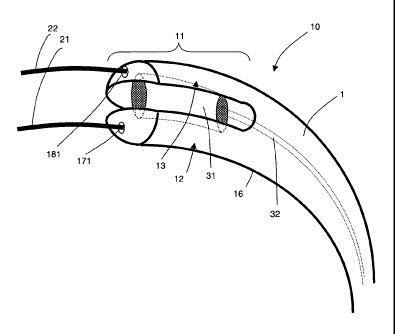
In Figs. la, lb, 2 and 3, a catheter apparatus 10 according to a first
embodiment of the present
invention is shown, which comprises a catheter 1, having a tip region 11. The
tip region 11 is
located at the distal end of the catheter and comprises first and second
sections 12, 13 which are
relatively moveable. The first and second sections 12, 13 are formed by a
split 14, which extends
across a distal end face 15 of the catheter 1 and along opposing sides of the
catheter walls 16,
dividing the tip region 11 into the two sections 12, 13. The catheter 1 has a
cross-section which is
substantially circular, and the first and second sections 12, 13 have cross-
sections which are
substantially semi-circular, in a direction perpendicular to the longitudinal
direction of the catheter 1.
CA 02711745 2010-07-08
WO 2009/050478
PCT/GB2008/003522
The first and second sections 12, 13 comprise first and second lumens 17, 18
respectively
(see Fig. 2), the lumens extending from the proximal end (not shown) of the
catheter 1 to
distal openings 171, 181 on the distal end face 15 of the catheter. The first
and second
lumens 17, 18 are arranged to accommodate first and second guidewires 21, 22
5 respectively. In the Figures, the guidewires 21, 22 are shown projecting
from the distal
openings 171, 181 of the lumens 17, 18.
The first guidewire 21 is provided to guide the catheter 1 to a desired region
of a blood
vessel, adjacent a chronic total occlusion (CTO). The second guidewire 22 is
provided to
10 probe the CTO, to find a pathway therethrough. In this embodiment, the
guidewires 21, 22
have 0.014" (0.36 mm) diameters.
The first and second sections 12, 13 are separable using an inflatable balloon
31 provided
within the catheter 1. The inflatable balloon 31 is located between opposing
inner walls 121,
15 131 of the first and second sections 12, 13 respectively and is
arranged, upon inflation, to
press against the inner walls 121, 131 in order to push the first and second
sections 12, 13
apart, as shown in Fig. lb. The inflatable balloon 31 is connected to a tube
32, which
extends to the proximal end of the catheter 1 where fluid (preferably liquid)
can be pumped
into the tube 32 to inflate the balloon 31. The degree of separation between
the first and
second sections 12, 13 can be controlled by controlling the degree of
inflation of the
inflatable balloon 31. Although in this embodiment the inner walls 121, 131
remain
substantially parallel as they are moved apart, the angle of the inner walls
121, 131 may be
arranged to change relative to each other upon inflation of the balloon 31,
e.g. diverge
toward the distal end face 15 of the catheter 1, in order to changing the
angle of the second
guidewire 22 projecting from the respective distal opening 181.
Since the first and second sections 12, 13 can be moved apart, the position of
the second
lumen 18, which comprises the second (probe) guidewire 22, can be adjusted
relative to the
CA 02711745 2010-07-08
WO 2009/050478
PCT/GB2008/003522
16
CTO and thus the second guidewire 22 can probe different positions of the
calcified cap of
the CTO in order to find an appropriate pathway, such as a microvessel,
through the CTO.
Once through, a larger guidewire may be inserted through the pathway to widen
the pathway
such that a balloon catheter can be inserted through the CTO. The inserted
balloon can
then be inflated, crushing the calcification and plaque of the CTO against the
vessel wall. A
stent can then be inserted into the open vessel and expanded to ensure the
vessel remains
open.
To enable a greater area of the calcified cap of the CTO to be probed by the
second
guidewire 22, the catheter apparatus is arranged to be rotatable. In this
embodiment, the
catheter 1 is arranged to be rotatable within an introducer shaft 23 (see Fig.
3), which is a
stiff hollow sleeve member through which the catheter 1 extends. To allow
stable rotation of
the catheter 1, the introducer shaft 23 comprises an inflatable balloon 24 for
anchoring the
shaft 23 against the walls of the blood vessel adjacent the CTO. As indicated
by the
patterning in Fig. 3, the walls 16 of the catheter 1 have braiding to provide
reinforcement, the
braiding being different at the tip region 11 of the catheter 1 to the rest of
the catheter to
permit the separation of the first and second sections 12, 13.
Although, in this embodiment, the catheter 1 is rotated within the introducer
shaft 23, the
catheter 1 may alternatively be rotated about the longitudinal axis of the
first guidewire 21.
To control rotation, the proximal end (not shown) of the catheter 1 may be
manipulated by
hand.
Since the second guidewire 22 can be moved in a linear direction, by changing
the
separation of the first and second sections 12, 13, and in a rotational
direction, by rotating of
the catheter 1, a substantially circular or annular area of the calcified cap
of the CTO may be
CA 02711745 2010-07-08
WO 2009/050478
PCT/GB2008/003522
17
swept out and probed by the second guidewire 22. Having a larger probe area
means that
versatility of the catheter apparatus is enhanced; it is more likely that the
guidewire 22 can
be manipulated to probe and travel through an appropriate pathway of the CTO.
In Figs. 4a and 4b, a tip region 11' of a catheter apparatus according to a
second
embodiment of the present invention is shown. The catheter apparatus of the
second
embodiment has generally the same features and works under generally the same
principles
as the catheter apparatus 10 according to the first embodiment, except that
the inflatable
balloon 31' is positioned to surround a section of the first lumen 17.
Effectively, a standard
balloon catheter may be used to provide the first lumen 17 and balloon 31'.
The inflatable balloon 311s located within a cavity in the first section 12.
The cavity has an
opening adjacent the inner wall 131 of the second section 13 such that, upon
inflation, the
balloon can press against the inner wall 131 to separate the first and second
sections 12, 13.
Since the balloon surrounds a section of the first lumen 17, the tip region
11' can take a
substantially lower profile, and may therefore extend along narrower blood
vessels.
In Figs. 5a and 5b, a tip region 11" of a catheter apparatus according to a
third embodiment
of the present invention is shown. The catheter apparatus of the third
embodiment has
generally the same features and works under generally the same principles as
the catheter
apparatuses according to the first and second embodiments, except that a wedge
element
41 is provided to separate the first and second sections 12, 13 at the tip
region 11" of the
catheter 1, rather than an inflatable balloon 31, 31'. Features of the third
embodiment
corresponding to features of the first and second embodiments are given the
same reference
numerals, and will not be described again.
CA 02711745 2010-07-08
WO 2009/050478
PCT/GB2008/003522
18
The wedge element 41 is connected to an elongate control element 42, which
extends to the
proximal end of the catheter 1, for control by e.g., a doctor or clinician. As
seen in cross
section, the wedge element 41 is thick at a distal end 411 and tapers to a
point at a proximal
end 412.
By pulling the elongate control element 42, the wedge element 41 can be moved
from a first
position as shown in Fig. 4a, where it is located proximate the distal end
face 15 of the
catheter 1, to a second position in which it is fully located between the
inner walls 121, 131
of the first and second sections 12, 13 as shown in Fig. 4b. The wedge element
41 forces
the first and second sections 12, 13 apart as it moves from the first position
to the second
position. The elongate control element 42 is stiff so that it can also be
pushed in order to
move the wedge element 41 back to the first position. The position of the
wedge element
41 can be varied between the first and second positions to change the
separation of the first
and second sections 12, 13 to the desired degree.
In Figs. 6a to 6d, a tip region 11¨ of a catheter apparatus according to a
fourth embodiment
of the present invention is shown. The catheter apparatus of the fourth
embodiment has
generally the same features and works under generally the same principles as
the catheter
apparatuses according to the previous embodiments, except that a cam element
51 is
provided to separate the first and second sections 12, 13 at the tip region
11¨ of the catheter
1, rather than an inflatable balloon 31, 31' or a wedge element 41. Features
of the third
embodiment corresponding to features of the first and second embodiments are
given the
same reference numerals, and are not described again.
The cam element 51 is connected to an elongate control element 52, which
extends to the
proximal end of the catheter 1, for control by e.g., a doctor or clinician. In
this embodiment,
the cam element 51 is a plate shaped element with first opposing parallel
surfaces 53a, 53b
CA 02711745 2010-07-08
WO 2009/050478
PCT/GB2008/003522
19
and second opposing parallel surfaces 54a, 54b, the first opposing surfaces
53a, 53b having
smaller separation than the second opposing surfaces 54a, 54b.
By rotating the elongate control element 52, the cam element 51 can be rotated
about an
axis substantially parallel to the longitudinal direction of the catheter 1
from a first position as
shown in Figs. 6a and 6b, where its first opposing surfaces 53a, 53b abut the
inner walls
121, 131 of the first and second sections 12, 13, to a second position in
which its second
opposing surfaces 54a, 54b, which are spaced further apart than the first
opposing surfaces,
abut the inner walls 121, 131 of the first and second sections 12, 13 as shown
in Figs. 6c
and 6d. The cam element 51 forces the first and second sections apart as it
rotates from the
first position to the second position. The elongate control element 52 can be
rotated in either
direction, or rotated 360 degrees, so that the cam element 51 can be moved
back to the first
position from the second position. The position of the cam element 51 can be
varied
between the first and second positions to change the separation of the first
and second
sections 12, 13 to the desired degree.
In Figs. 7a and 7b, a tip region 11" of a catheter apparatus according to a
fifth embodiment
of the present invention is shown. The catheter apparatus of the fifth
embodiment has
generally the same features and works under generally the same principles as
the catheter
apparatuses according to the previous embodiments, except that magnets 61, 62,
63 are
provided to separate the first and second sections 12, 13 at the tip region
11" of the
catheter 1, rather than an inflatable balloon 31, 31', wedge element 41 or cam
element 51.
Features of the fifth embodiment corresponding to features of the previous
embodiments are
given the same reference numerals, and will not be described again.
A first magnet 61 is embedded in the first section 12, adjacent the inner wall
121; a second
magnet 62 is embedded in the second section 13, adjacent the inner wall 131,
and a third
magnet 63 is located between the first and second sections 12, 13.
CA 02711745 2010-07-08
WO 2009/050478 PCT/GB2008/003522
In this embodiment, the magnets 61, 62 or 63 are permanent magnets, although
they could
be, alternatively, electromagnets or a combination of permanent magnets and
electromagnets.
5
Each magnet 61, 62, 63 has a north pole and a south pole. In this embodiment,
the north
pole 61n of the first magnet 61 is adjacent the inner wall 121 of the first
section 12, and the
south pole 62s of the second magnet 62 is adjacent the inner wall 131 of the
second section
13. The third magnet is connected to an elongate control element 64, which
extends from
10 the third magnet 63 to the proximal end of the catheter 1, for control
by e.g., a doctor or
clinician.
By rotating the elongate control element 62, the third magnet 63 can be
rotated about an
axis substantially parallel to the longitudinal direction of the catheter 1
from a first position to
15 a second position. In the first position, as shown in Figs. 7a and 7b,
the south pole 63s of
the third magnet 62 is adjacent the north pole 61n of the first magnet 61, and
the north pole
63n of the third magnet 63 is adjacent the south pole 62s of the second magnet
62. In the
second position, as shown in Figs. 7c and 7d, the north pole 63n of the third
magnet 62 is
adjacent the north pole 61n of the first magnet 61, and the south pole 63s of
the third
20 magnet 63 is adjacent the south pole 62s of the second magnet 62. The
arrangement is
such that: in the first position, the first and second magnet 61, 62 and thus
the first and
second sections 12, 13 are attracted toward the third magnet and are therefore
closer
together or touching; and in the second position, the first and second magnets
61, 62 and
thus the first and second sections 12, 13, are repelled from the third magnet
and are
therefore further apart.
The position of the magnet element 63 can be varied between the first and
second positions
to change the separation of the first and second sections 12, 13 to the
desired degree.
CA 02711745 2010-07-08
WO 2009/050478 PCT/GB2008/003522
21
If electromagnets are used, rather than rotating the third magnet to change
the positions of
its north and south poles, the third magnet can be kept stationary, and the
polarity of the
power supply to the third magnet, or the polarity of power supplies to the
first and second
magnet can be switched to change between the attractive and repulsive states
discussed
above. Furthermore, to vary the degree of separation of the first and second
sections 12,
13, the strength of the power supply can be adjusted.
In figs. 8a and 8b, a catheter apparatus 101 according to a sixth embodiment
of the present
invention is shown. The apparatus comprises a balloon catheter 71 that has an
inflatable
balloon 72 adjacent a tip region 73 at the distal end of the catheter 71. The
balloon catheter
extends through a sleeve member 74 having a proximal opening 741 and a distal
opening
742. The sleeve member 74 can be inserted into the blood vessel along with the
balloon
catheter 71. A guidewire 75 extends through the balloon catheter 71 and
projects from a
distal opening 731 at the tip region 73 of the balloon catheter 71.
A projecting part 76 extends from the sleeve member 74 at its distal opening
742. The
projecting part 76 has a deflection surface 761 that runs alongside the tip
region 73 of the
balloon catheter 71, adjacent the inflatable balloon 72. As seen in Fig. 8a,
when the balloon
72 is deflated it makes no contact with the deflection surface 761. However,
upon inflation
the balloon 72 is arranged to press against the deflection surface 761,
causing the tip region
73 of the balloon catheter 71 to deflect away from the deflection surface 761.
The sleeve member may be held in position, e.g. by an anchoring member (not
shown) in a
blood vessel adjacent a CTO. By inflating and deflating the balloon 72, the
tip region 73 of
the catheter 71, and thus the guidewire 75 projecting therefrom, will move
relative to the
deflection surface 761 and therefore the CTO. Accordingly, the guidewire 75
can probe
different positions of the calcified cap of the CTO in order to find an
appropriate pathway,
CA 02711745 2010-07-08
WO 2009/050478
PCT/GB2008/003522
22
such as a microvessel, through the CTO. As in the embodiments described above,
the
catheter apparatus may be rotatable so that the guidewire may probe a
substantially circular
or annular area of the cap of the CTO.
Figs. 9a to 9c shows a catheter apparatus comprising a catheter 81 which has a
lumen 82
through which a guidewire 83 extends. A first guidewire section 83a of the
guidewire 83
projects from the distal end of the catheter 81 and has a spiral shape. The
first guidewire
section 83a is connected to a second guidewire section 83b of the first
guidewire 83 that is
substantially linear, and which is located within the lumen 82. As can be seen
from the distal
end view of the guidewire 83 in Fig. 9b, the spiral shaped first guidewire
section 83a has a
substantially circular perimeter, and is joined to the linear second guidewire
section 83a at a
position 83c at the centre of the circle. Essentially, the first guidewire
section 83a spirals
around a central axis (indicated by line z in Fig. 9a) which is an extension
of the longitudinal
axis of the second guidewire section 83b.
The first section 83a can be slid in and out of the lumen 82. When located in
the lumen as
shown in Fig. 9c, the first section 83a is forced to collapse and take a
linear shape, as the
second section 83b.
Fig. 10 shows a tip region 11' of a catheter apparatus as described above with
respect to the
second embodiment of the present invention. The tip region 11' is located in a
blood vessel
801, adjacent a CTO 802. A guidewire 83, as described above with respect to
Figs. 9a to
9c, is disposed in the first lumen 17 of the catheter. The spiral shaped first
section 83a of
the guidewire extends from the distal end of the catheter and abuts the blood
vessel walls
803.
Since the first guidewire section 83a spirals around a central axis which is
an extension of
the longitudinal axis of the second guidewire section 83b, the second
guidewire section 83b
CA 02711745 2010-07-08
WO 2009/050478
PCT/GB2008/003522
23
is fixed in a central position between the blood vessel walls. By fixing the
position of the
second guidewire section 83b centrally with respect to the blood vessel walls,
variation of the
separation between the first and second guidewires 83, 22, and rotation of the
second
guidewire 22 about the longitudinal axis of the second guidewire section 83b,
will ensure that
a circularly symmetrical central area of a calcified cap 804 of the CTO 802
can be probed.
In Figs. lla to 12b, the tip region 91 of a catheter apparatus 9 according to
a seventh
embodiment of the present invention is shown. In this embodiment, the catheter
apparatus 9
includes a catheter 92 comprising seven lumens. Each lumen is provided by a
respective
tube 921, 931 that extends in the elongation direction of the catheter 92
between the distal
and proximal ends 901, 902 of the catheter 92. A distal opening 922, 932 of
each of the
lumens is provided at the distal end 901 of the catheter 92.
As shown in Fig. 11a, the distal openings 932 of six of the seven lumens
(outer lumens) are
arranged in a circular formation around the distal opening 922 of the other of
the seven
lumens (central lumen).
With reference to Figs 11 b, 12b and 14a to 14c, along most of the length of
the catheter 9,
between its distal and proximal ends 901, 902, the outer tubes 931 providing
the outer
lumens are attached to one another, directly or indirectly. However, at the
tip region 91 of
the catheter 92, proximate the distal end 901, the outer tubes 931 are not
attached to one
another, and are therefore moveable relative to each other and to the central
tube 921, at
the tip region 91.
The catheter apparatus comprises a wedge element 94 that is operable to
separate the
distal ends 922, 932 of the lumens at the tip region 91. The central tube 921,
providing the
central lumen, is fixed to the wedge element 94 to provide an elongate control
element,
which extends to the proximal end 902 of the catheter 92, for control of the
wedge element
CA 02711745 2010-07-08
WO 2009/050478
PCT/GB2008/003522
24
94 by e.g., a doctor or clinician. The central tube 921 and the outer tubes
931 are relatively
moveable in the elongation direction of the catheter 92.
With reference to Figs. 13a to 13g, the wedge element 94 is substantially
conical, with side
surfaces 943 extending between a distal end surface 941 and a proximal end
surface 942.
The diameter of the wedge element 94 tapers from the distal end surface 941 to
the proximal
end surface 942. The side surfaces 943 are provided with a plurality of
channels 944 for
guiding the outer tubes 931 of the catheter 92. The wedge element 94 has a
central conduit
945, extending between distal and proximal end openings 9411, 9421, into which
the central
tube 931 is located. Effectively, the distal end opening 9411 of the conduit
945 provides the
distal opening 922 of the central lumen. In this embodiment, the central tube
921 is fixed to
inner surface of the central conduit 945 by glue. To direct the glue between
the inner
surface of the central conduit 945 and the central tube 921, a plurality of
wicking channels
9451 are provided along the inner surface.
As indicated above, the central tube 921 acts as an elongate control element
for the wedge
element 94 (although in alternative embodiments, a control element separate
from the
central tube 921 may be provided). Since the central tube 921 is moveable
relative to the
outer tubes 931, the wedge element 94 is also moveable relative to the outer
tubes 931. By
relatively moving the wedge element 94 and the outer tubes 931, the wedge
element 94 can
be moved from a first position as shown in Fig. 11b, 14a and 15a, where it is
positioned
outside the catheter 92, at the distal end 901 of the catheter 92, to a second
position as
shown in Figs. 12b and 14c and 15b, where it is located between the outer
tubes 931 at the
tip region 91 of the catheter 92. As it moves from the first position to the
second position,
the wedge element 94 forces the outer tubes 931 apart, and thus the distal
openings 932 of
the outer lumens apart. Relative movement of the wedge element 94 and the
outer tubes
931 can be achieved by, for example, moving the wedge element 94, whilst
keeping the
outer tubes 931 generally stationary, or by moving the outer tubes 931 and
keeping the
CA 02711745 2010-07-08
WO 2009/050478
PCT/GB2008/003522
wedge element 94 generally stationary. The central tube 921 and/or outer tubes
931 are stiff
so that they can be pushed and pulled in order to relatively move the wedge
element 94
between the first and second positions. The position of the wedge element 94
can be varied
between the first and second positions (e.g. to an intermediate position as
shown in Fig.
5 14b) to change the separation of the distal end openings 922, 932 to the
desired degree. It
should be noted that the distal end opening 922 of the central lumen is not
shown in Figs.
14a to 14b.
In this embodiment, the central lumen provided by the central tube 921 is
intended to provide
10 a path for a first guidewire, which guidewire is for guiding the
catheter 92 to a desired region
of a blood vessel, adjacent a chronic total occlusion (CTO). The outer lumens
provided by
the outer tubes 931 are intended to provide a plurality of selectable paths
for a second
guidewire that is to probe the CTO, to find a pathway therethrough.
Nevertheless, it is
conceived that the first guidewire could be extended through one of the outer
lumens,
15 leaving the central lumen available to provide one of the plurality of
selectable paths for the
second guidewire, along with the remaining outer lumens.
By making the distal openings 922, 932 of the lumens separable at the tip
region 91 of the
catheter 92, the distal openings 932 of the outer lumens can each be moved
along different
20 linear paths, the paths extending radially from the distal opening 922
of the central lumen.
By having the plurality of outer lumens, the second guidewire can be moved
from one outer
lumen to another, and therefore along the different linear paths upon
actuation of the wedge
element 94, in order to probe different areas of the CTO. This means that
little or no rotation
of the catheter apparatus 9 may be necessary to probe a relatively large
surface area of the
25 CTO. In essence, instead of rotating the catheter apparatus 9 to probe a
larger area of the
CTO, as described with respect to earlier embodiments, the second guidewire
can be moved
from one outer lumen to another. The second guidewires may have bent and/or
bendable
distal ends, as represented in Fig. 16a. Accordingly, whilst projecting out of
the distal end
CA 02711745 2010-07-08
WO 2009/050478
PCT/GB2008/003522
26
openings 922, 932 of the lumens, the distal ends of the second guidewire can
be bent and/or
rotated to probe a greater area of the CTO. The area that such a guidewire can
probe using
the apparatus of this embodiment is is represent by the circles 9001 in Fig.
16b.
With reference to Figs. 17a to 17c, at the proximal end 902 of the catheter
92, a guidewire
introducer 95 is provided to assist in locating the guidewires in the central
and outer tubes
921, 931. The guidewire introducer 95 comprises a housing having a cylindrical
section 951
and a conical section 952 and a plurality of conduits 953 extending through
the cylindrical
and conical sections 951, 952, each conduit 953 being adapted to channel a
guidewire into a
respective one of the outer and central lumens of the catheter 92. The
conduits 953 have
input openings 955 located at a proximal end face 954 of the housing. The
conduits 953
increase in diameter toward their input openings 955, to enable easier
introduction of a
guidewire into the conduits 953. The conduits 953 extend from their input
openings 955,
through the cylindrical section 951 and into the conical section 952 of the
housing, where
they converge (not shown). The outer and central lumens of the catheter 92 are
each
connected to a respective conduit 953 at the distal end 9521 of the conical
section 952.
The introducer 95 may comprise tactile features, to enable a person to
distinguish by touch
one input opening 955 from another. In one embodiment, shown in Figs. 18a and
18b, the
tactile features are provided by a plurality of steps 956 forming the proximal
end face 954' of
the housing, each input opening 955 being located on a different one of the
steps 956. The
arrangement of steps 956 may provide a 'spiral staircase' arrangement to the
proximal end
face 945' of the housing. In another embodiment, shown in Figs. 19a and 19b,
outer
surfaces of the housing are provided with a plurality of protrusions 957. The
protrusions 957
are clustered together in lines (although alternative arrangements are
possible) adjacent
each input opening, the number of protrusions 957 in each cluster being
distinct to the
adjacent input opening 955. Although not shown, it is also conceived that the
tactile features
might be provided by grooves or depressions in the housing.
CA 02711745 2010-07-08
WO 2009/050478
PCT/GB2008/003522
27
To control the movement of the wedge element 94 relative to the outer tubes
931, a
controller is also provided at the proximal end 902 of the catheter. The
controller comprises
a housing supporting an actuator element that, e.g. via a rotational to linear
force translator
and/or gearing etc., is connected to the central tube 921, or connected to the
outer tubes
931, in order to control relative movement of the wedge element 94 and the
outer tubes 931.
The actuator element is moveable relative to the housing to control the
relative movement.
In one embodiment (see Fig. 20), the actuator element of the controller 96 is
a drum 961.
The drum 961 is rotatable around the housing 962 and about the axis of
elongation of the
control element. In another embodiment (see Fig. 21), the actuator element of
the controller
96' is a wheel 963. The wheel 963 is rotatable in a slot in the housing 964
and about an axis
perpendicular to the axis of elongation of the control element. In yet another
embodiment
(see Fig. 22), the actuator element of the controller 96" is a push element
965 with a handle
9651. The push element 965 is moveable in and out of the housing 966 along the
axis of
elongation of the control element, and is linked directly to the control
element.
A controller 97 according to another embodiment is shown in Figs. 23a to 23e.
The
controller 97 includes an actuator, for moving outer tubes 931 relative to the
central tube
921, in combination with features of an introducer, to assist in locating the
guidewires in the
central and outer lumens of the central and outer tubes 921, 922, in a similar
manner to the
introducers described above.
In more detail, the controller 97 comprises an elongate housing 971, having
sidewalls 972
extending between distal and proximal ends 973, 974. A button 9761 or lever is
provided
that is slidable within a slot 9762 in the sidewalls 972 of the housing 971.
The button 9761 is
part of an actuator mechanism 976, discussed further below. With reference to
Fig. 23d, at
the proximal end 974 of the housing 971, a central input opening 977 is
provided for a
guidewire to enter the central lumen provided by the central tube 921, and
outer input
CA 02711745 2010-07-08
WO 2009/050478
PCT/GB2008/003522
28
openings 978, are provided for a guidewire to enter the outer lumens provided
by the outer
tubes 931. Although not shown, the input openings 977, 978 may have closure
means to
prevent fluid, e.g. blood, leaking through them from a patient. For example,
the openings
977, 978 may have valves or luer lock additions. This arrangement may also
permit flushing
of the tubes 921, 931 prior to insertion of the catheter 92 in a patient, or
allow for 'blowing off'
of the device whilst the guidewires(s) are in place.
Numbering is provided on the housing, adjacent each outer input opening, to
distinguish the
outer input openings from one another. At the distal end of the housing 971, a
distal end
opening 979 is provided through which the catheter 92, comprising the central
and outer
tubes 921, 931, projects from the housing. A hand grip 9711 is provided on the
bottom of
the housing 971.
The actuator mechanism 976 can be seen in Figs. 24 to 26b. The button 9761 is
pivotally
and slidably mounted to an arm 9763 at a first pivot point A. This is achieved
by locating a
pin 9764 connected to the button 9761 in a first slot 9765 provided in the arm
9763. The
arm 9763 is pivotally mounted to a support 9766, fixed to the housing 971, at
a second pivot
point B. The central tube 921 is fixed to the housing 971 adjacent the central
input opening
977 and travels through the housing 971, in the elongation direction of the
housing, in a
substantially straight line. The outer tubes 931 are fixed to the housing 971
adjacent
respective outer input openings 978, and travel in the housing along
substantially curved
paths to a convergent point where, along with the central tube 921, they
extend through a
sheath 9311 located in the housing 971. The sheath 9311 is fixed to the outer
tubes 931 but
not the central tube 921. Since the outer tubes 931 are flexible and follow
curved paths
before extending into the sheath 9311, movement of the sheath 9311 and the
outer tubes
931 is possible relative to the housing 971 and relative to the central tube
921. The sheath
9311 is pivotally and slidably mounted to the arm 9763 at a pivot point C,
intermediate the
CA 02711745 2010-07-08
WO 2009/050478
PCT/GB2008/003522
29
first and second pivot points A, B. This is achieved by locating a pin 9767
fixed to the sheath
9311 in a second slot 9768 provided in the arm 9763.
When the button 9761 is caused to slide in the slot 9762 of the housing 971,
in the
elongation direction of the housing 971, the arrangement is such that the
button 9761 forces
the arm 9763 to rotate about point B, which also forces the sheath 9311 and
outer tubes 931
to move in the elongation direction of the housing 971, relative to the fixed
central tube 921,
causing the wedge element 94 connected to the central tube 921 at the tip
region 901 of the
apparatus to move relative to the outer tubes 931, changing the separation of
the distal end
openings 932 of the outer tubes 931, as discussed above. The movement of the
button 9761
and arm 9763 can be seen by comparing Figs. 26a and 26b. The actuator
mechanism 976
may be arranged so as to prevent accidental removal of the catheter 92 from
the patient with
the tip region 901 expanded (i.e. with the distal end openings 932
substantially separated).
Since the outer tubes 931 are connected to the arm 9763 via the sheath 9311 at
a position
closer to pivot point B than the button 9761, as the arm 9763 rotates, the
distance that the
outer tubes 931 travel is less than that of the button 9761. This scaling of
movement
between the button 9761 and the outer tubes 931 provides for more precise
control of the
relative movement of the wedge element 94 and the outer tubes 931. In this
embodiment,
there is a 4:1 movement ratio between the button 9761 and the outer tubes 931.
Accordingly, when the button 9761 is moved 20 mm along the slot 9762, in the
elongation
direction of the housing 971, the outer tubes 931 move only 5 mm in the
elongation direction
of the housing 971. It is considered that similar scaling arrangements could
be applied to the
controllers discussed above with respect to the Figs. 20 to 22.
The button 9761 and the outer tubes 931 are both pivotally and slidably
mounted to the arm
9763 as described above so that, when the arm 9763 rotates about pivot point
B, the button
9761 can maintain the same orientation relative to the slot 9762 in the
housing 971 and
CA 02711745 2010-07-08
WO 2009/050478 PCT/GB2008/003522
sheath 9311 and the outer tubes 931 can maintain the same orientation relative
to the distal
end opening 979 of the housing and the central tube 921, preventing possible
jamming
and/or breakage of the controller 97.
=