Note: Descriptions are shown in the official language in which they were submitted.
CA 02711939 2010-07-08
WO 2009/090096 PCT/EP2009/000275
Narrow Band Fiber Raman Optical Amplifier
The invention relates to a narrow band fiber Raman optical amplifier.
Commonly optical Raman fiber amplifiers are known where light with a pump
frequency in
an optical fiber amplifies light which corresponds to a Stokes line of the
Raman process.
The frequency difference between the pump light and the light to be amplified
may be typi-
cally in the range of 40 nm to 80 nm such as 60 nm.
The Raman process is enhanced e.g. by germanium as an impurity and hence e.g.
germa-
nium doped silica fibers are often used for Raman amplifiers. Currently
existing Raman am-
plifiers can reach high powers, but not narrow amplified linewidths at the
same time.
Several problems in Raman fiber amplification can be identified. For example,
the stimu-
lated Brillouin (SBS) light scattering or Four-Wave mixing (FWM) lead to a
linewidth en-
hancement. This may be undesired for various reasons. A broader linewidth is
not favorable
for spectroscopic resolution. Further this linewidth broadening usually
introduces losses
since such light out of a resonant mode or out of a desired wavelength range
will be lost.
Raman amplification relies on fiber nonlinearity. This nonlinearity can be
described by a
tensor of the third level, often referred to as the X(3)-tensor (see e.g. G.
P. Agrawal, "Nonlin-
ear Fiber Optics", 4th ed., Academic Press, USA). Unfortunately, this
nonlinearity also in-
cludes other unwanted effects such as four-wave mixing (FWM) and stimulated
Brillouin
scattering (SBS). The strength of the nonlinearity is commonly characterized
by the scalar
quantity
3 ( )
nZ = 8n Re(x~,.), 1.1
where n is the linear part of the refractive index of the fiber, ReO denotes
the real part, and
xxxx stands for one specific tensor element.
FWM leads to the mixing of different spectral components and induces line
broadening. Al-
so, light power at a desired frequency can mix with optical noise and hence
signal energy is
lost.
CA 02711939 2012-01-11
2
Specifically, SBS is a serious detriment in fiber lasers: High laser light
intensities create
acoustic phonons in the fiber that induce a refractive index grating. The
light is
backscattered from this grating, an effect which both limits the maximum
transmitted
power in the fiber and may destroy previous amplifier stages or a seed laser.
The onset
of SBS happens suddenly when exceeding a certain power level. This power level
depends on a number of system parameters such as fiber length, bandwidth of
the light,
and fiber nonlinearity. In particular, the fiber glass composition, possible
glass dopants,
and the fiber index profile have a strong influence. In general, SBS will be
most severe
(start at the lowest power threshold) when using narrowband signals in long,
uniform
optical fibers. These circumstances have limited the use of Raman amplifiers
to either
wideband and/or low power applications in the past.
Stimulated Raman amplification (SRS) can be mathematically described as
dI,
dz = 9RIJp - asIs,
(0.1)
where z is distance along the fiber, /S denotes the signal intensity, /p the
pump intensity,
gR the Raman gain coefficient, and as denotes linear light attenuation. A
similar equation
holds for SBS:
dl, dz galslp -asIs,
(0.2)
where gB is the Brillouin gain coefficient and the first minus sign indicates
power loss.
It is therefore the object of the present invention to provide an optical
Raman amplifier,
an optical light source and use of an optical fiber and a method for
amplifying light by a
Raman amplifier which allows for high powers/high amplifications and very
narrow
linewidths.
This object is solved with the Raman amplifier, an optical light source, the
use of an
optical fiber and the method for amplifying light by a Raman fiber amplifier
of the present
invention. Preferred embodiments are disclosed in the dependent claims.
CA 02711939 2012-07-06
2a
In one aspect, the present invention resides in an Optical Raman fiber
amplifier with an
amplification fiber, wherein at least one section thereof has a ratio of Raman
gain
coefficient gR to Brillouin gB gain coefficient of gR/gg larger than 0.001 at
the fiber
operating temperature and a vacuum wavelength of 1064 nm, and a pump laser
characterized in that the amplification fiber has a total length of less than
300 meters
and the pump laser has a power of more than 10 W.
In another aspect, the present invention resides in a use of an optical fiber,
such as a
silica fiber, for a Raman optical amplifier wherein at least one section of
the optical fiber
has a ratio of Raman gain coefficient gR to Brillouin gB gain coefficient of
gR/gB larger
than 0.001 at the used fiber operating temperature and a vacuum wavelength of
1064
nm, characterized in that the amplification fiber has a total length of less
than 300
meters and the optical pump power is at least 10 W.
In a further aspect, the present invention resides in a method of amplifying
light by a
Raman fiber amplifier, wherein the light is amplified in an optical fiber,
wherein at least
one section thereof has a ratio of Raman gain coefficient gR to Brillouin gB
gain
coefficient of gR/gB larger than 0.001 at the fiber operating temperature and
a vacuum
wavelength of 1064 nm, characterized in that the amplification fiber has a
total length of
less than 300 meters and the optical pump power is at least 10 W.
According to the invention a fiber with a high ratio between the Raman gain
coefficient
and the Brillouin gain coefficient is employed. It turned out that for such
fibers it is
possible to arrive to high powers by Raman amplification without the onset of
stimulated
Brillouin scattering.
CA 02711939 2010-07-08
WO 2009/090096 PCT/EP2009/000275
3
Both SRS and SBS have a threshold-like behavior with onsets above the pump
intensities
It', SRS ,16Leff gR, Im, SBS 21LeffO (0.3)
P p where the effective fiber length Leff is defined as
LCff 1- exp(-apL) (0.4)
ap
where ap denotes pump light attenuation and L is fiber length. The onsets /Pth
in 1.4 are de-
fined to be the pump intensities which induce the same intensity in the Stokes
lines of the
Raman or SBS, respectively. It was found to be advantageous for the aim of the
present
invention to keep the onset ratio
th. SRS
Ip 16 gR (0.5)
Ich,sBs 21 gB'
P
as large as possible. The ratio gRIgB depends on wavelength, the chemical
composition and
the geometry of the optical fiber in a complicated way but can be controlled
by appropriately
choosing those parameters.
Both gR and gB depend on wavelength and on the fiber temperature. The SRS
coefficient gR
is approximately inversely proportional to the vacuum wavelength A0, while gB
is propor-
tional to n7/A0, (note that n depends on wavelength as well). In order to
properly define the
specified ratio its value is defined at an arbitrary vacuum wavelength of 1064
nm. This,
however, is only a reference wavelength at which the ratio can be measured.
This does not
imply that the amplifier can (only) be or shall be used at such wavelength.
The temperature dependence of gR and ge is more complicated. The ratio gR/gB
is specified
for the operating temperature which usually is room temperature such as 300K.
The ampli-
fier may have a temperature control for the fiber. Here operating temperatures
higher or
lower than 300 K may be set by such a temperature controller such as e.g. more
than 350,
380, 400, 500, 600, 700 or 800 K or even more; or less than 275, 250, 225,
200, 175, 150 ,
125 or 100 K. In this case the operating temperature where the ratio of gRIgB
is specified
may be different from room temperature. For this purpose the fiber may be e.g.
located on a
temperature controlled heating or cooling element such as a cylindrical
element or may be
provided inside a temperature controlled housing.
CA 02711939 2010-07-08
WO 2009/090096 PCT/EP2009/000275
4
A fiber with a relative low Raman amplification potential (e.g. given by a low
value of n2)
may be used such as common fibers used for e.g. long distance
telecommunication sys-
tems, which are not especially adapted for Raman amplification. Those fibers
are chosen,
although high powers are desired. The low Raman amplification potential is
compensated
by relatively high pump powers and relatively long fibers. It turned out that
with this particu-
lar combination of measures high powers can be obtained and at the same time
the line-
width can be maintained narrow.
According to a preferred embodiment, we employ amplification fibers with a low
Brillouin
gain coefficient ge such as ge < 10-10 m1W. Since a small value of ge usually
(but not in all
fibers) implies a low value of the Raman gain coefficient gR as well,
selecting fibers with
small ge for Raman amplifiers is counter-intuitive to the person skilled in
the art.
A possible figure of merit for high-power narrow-band Raman amplifiers is the
ratio
BFWHM/Pout of full spectral width at half maximum (FWHM) intensity signal
bandwidth BFWHM
to average signal output power Pout. With the presented technique it is
possible to achieve a
ratio of BFWHM/POUt < 33 MHz/W and also of BFWHM/Pout < 10 MHz/W.
According to preferred embodiments, a combination of measures is used to
increase the
SBS threshold in the Raman amplifier. These measures include, but are not
limited to:
1. Providing fibers with a high ratio gR/ge of Raman to SBS gain coefficients
(such as more than 0.001, 0.002, 0.005 or 0.01),
2. Providing fibers whose longitudinal acoustic velocity in the core is higher
than in the cladding,
3. Providing heating of the fibers differentially, i.e. introducing a
temperature
gradient along the fiber at least in one section of the fiber,
4. Providing stretching the fibers differentially on e.g. a stretching
mandrel,
i.e. introduce a stress gradient along the fiber at least in one section,
5. Providing a high-power pump (such as e.g. at least 10, 15, 20, 30, 40 or
50 W optical pump power) to amplify the signal in a fiber as short as pos-
sible,
6. Providing a backward pumping scheme (pump light and signal traveling in
opposite directions in the fiber),
CA 02711939 2010-07-08
WO 2009/090096 PCT/EP2009/000275
7. Providing a narrow-band seed laser (less than e.g. 30 MHz spectral
bandwidth),
8. Providing the amplifier with multiple stages with optical isolators in be-
tween them (an isolator acts like a "light valve" and lets light only pass in
the forward direction),
9. Providing different fiber types in different stages,
10. Providing sections of different fiber types together within the same
stage,
those different types being joined e.g. by splicing ,
11. Selecting the lengths of all fibers in the system to optimize gain while
maintaining the highest possible SBS threshold. In particular, reduce the
fiber section lengths or fiber length inside different amplification stages
towards the output of the amplifier.
In this document, the term "stage" or "amplifier stage" denotes an amplifier
fiber portion with
its own pump input. In particular, a multi-stage amplifier can have more than
one pump in-
put of the same pump light propagation direction, and/or uses at least one
isolator between
two sections of pumped fiber. The pump light can be recycled between different
stages, i.e.
unconverted pump light of one stage can be re-injected into another stage.
With respect to the fiber selection, the previous art reports on the use of
fiber for Raman
amplifiers with high nonlinearities in order to achieve a high magnitude of
the Raman gain
coefficient (e.g. Z. Yusoff, J. H. Lee, W. Belardi, T. M. Monro, P. C. Teh,
and D. J. Richard-
son "Raman effects in a highly nonlinear holey fiber: amplification and
modulation", Optics
Letters, Vol. 27, No. 6, p.424-426 (2002), or Y. Li, S.D. Jackson, Y. Zhao, S.
Fleming, "Si-
multaneous operation of a Raman fiber amplifier and laser pumped by a dual-
wavelength
Nd/sup 3+/-doped fiber laser", J. of Lightwave Technology, Vol. 23, Issue 5,
p.1907-1912
(2005)). Such specialty fibers may contain high dopant concentrations and/or
very small fi-
ber cores and hence have small mode field diameters, inducing high power
densities and
thus high nonlinearities. Contrary to this teaching, some aspects of the
invention are also
based on "non-Raman" fibers, i.e. not specifically favoring Raman conversion,
with low do-
pant concentrations and/or standard core diameters. "Non-Raman fibers" in the
scope of
this document include single-mode fibers such as Corning SMF-28e fiber that
are otherwise
used e.g. for telecommunication applications, but not specifically
manufactured and/or in-
tended for use in Raman amplifiers.
CA 02711939 2010-07-08
WO 2009/090096 PCT/EP2009/000275
6
According to some aspects of the invention, a silica fiber with a nonlinearity
coefficient n2
smaller than 5 x 10-20 m2/W, 2 x 10"20 m2/W, 1 x 10-20 m2/W or 0.5 x 10"20
m2/W is used for
amplification purposes. Although the Raman gain in such silica fibers is
rather low, detri-
mental effects such as SBS and FWM are comparatively low as well. As a result,
the light
can be amplified without a significant increase in the linewidth, although
with low efficiency.
In order to obtain an amplifier, which emits a diffraction limited beam, the
fiber for amplifica-
tion is preferably a single mode fiber. A diffraction limited light beam
allows for good projec-
tion and good focusing of such beams with corresponding optics.
The fibers are preferably silica fibers. In this document, the term "dopant"
denotes an added
chemical substance to the fiber glass that alters its optical or acoustic
properties. Doping
may be intentional or unintentional (e.g., result from contaminations).
Typical dopants in-
clude, but are not limited to, germanium, aluminium, phosphor, bismuth,
magnesium, po-
tassium, fluorine, ytterbium, thulium and boron.
The content of doping materials and, in particular of germanium, is preferably
less than 5
weight-%, 2, weight-%, 1 weight-% or even 0.5 weight-%.
Polarization maintaining fibers may be used in order to provide a well defined
output polari-
zation and to provide a stable operation of the amplifier.
By providing fibers with a longitudinal acoustic velocity in the core being
higher than in the
cladding, the concentration of phonons in the core is suppressed such that a
higher thresh-
old for SBS is obtained.
Further by introducing inhomogeneities along the fiber e.g. by a temperature
gradient, a
stress gradient or different fiber types the SBS threshold can be further
pushed upwards,
since the formation of the phonon caused diffraction grating is hindered.
Nevertheless by
those measures some linewidth enhancement is caused, which may be acceptable,
de-
pending on the desired application. Those measures are favorable in order to
use relatively
long fibers which are helpful for compensating the low Raman amplification. In
case of tem-
perature gradients the operating temperature of the fiber varies along the
fiber length. In
those cases the term "operating temperature" or the like used in the claims is
considered to
be given by the highest present fiber temperature.
CA 02711939 2012-01-11
7
The fiber laser can emit temporally continuous (continuous wave, cw),
temporally
modulated, or pulsed light. The quoted powers are always time-averaged over a
statistically representative time span.
In case that different fiber types are used, a certain section of a certain
fiber type (or two
or three or more or all fiber types) is (are) preferably shorter than a
previous section in
the propagation direction of the signal light. In the downstream section the
light intensity
will be higher due to the amplification and therefore the SBS threshold be
reached at
shorter fiber lengths. Therefore along the direction of propagation the fiber
sections are
preferably getting shorter.
The length of the fiber (e.g. within one amplifier stage) should not be more
than 500 m
since otherwise, nonlinear effects like stimulated Brillouin light scattering
may set on at
power levels of several watts.
The inherent loss (in case of no pumping) of the fiber at the operating
wavelength is
preferably less than 3 db/km. At such low losses a configuration with a low
Raman
amplification can be realized.
The fiber amplifier is capable of delivering a power amplification of signal
power by more
than 1 dB, 3, dB, 6 dB, 10 dB, 20 dB or even up to 30 dB.
The amplifier is capable of outputting light with a power of a few Watt (2, 3,
4 or more
W), although the linewidth increase may be low.
Even with those relatively large amplifications and/or powers, the linewidth
of the output
light in comparison to the input light preferably does not increase by more
than a factor
of 10.
The optical amplifier preferably includes an optical pump source which is
arranged in the
backward and/or forward pumping scheme. In the backward pumping scheme, the
pump light and the light to be amplified travel in opposite directions and in
the forward
pumping scheme, they travel in the same direction. One or the other or both of
the
pumping schemes may be used. Pump lasers have at least 10 W optical pump power
but may even have powers of more than 20, 30, 40 or 50 Watt.
CA 02711939 2010-07-08
WO 2009/090096 PCT/EP2009/000275
8
The amplifier has an operating vacuum wavelength within the range of 500 -
1800 nm. In
this range optical fibers are available, which have a low loss such that even
with the rela-
tively small gain of undoped fibers or fibers with a low Raman gain
coefficient or nonlinearity
coefficient it is possible to obtain a net gain (gain due to amplification
minus loss).
It is advantageous in order to increase the amplification to use two, three,
four or more opti-
cal amplification stages. Each of the stages is an optical Raman amplifier
according to the
above or below-mentioned embodiments. A second or third stage here may still
provide an
amplification by a factor between 2 and 20. Different amplification stages are
preferably se-
parated by optical isolators.
Further in different stages preferably different fiber types are used and in
the direction of
signal light propagation the fiber length within the different stages
preferably becomes
shorter from stage to stage at least for one, two, three or more or all
stages.
It is to be noted that the amplifier preferably is a "one pass" amplifier.
This means that light
on the path of amplification is not reflected by e.g. fiber gratings, mirrors
or the like. This is
to avoid amplification of undesired wavelengths such as light due to
stimulated Brillouin light
scattering.
The optical light source has the seed light source and an optical amplifier as
mentioned be-
forehand or below for amplifying the light of the seed light source. The seed
light source
preferably has a single line spectrum with full width at half maximum
linewidth between
1 kHz and 300 MHz, depending on the desired final linewidth. Such a light
source may e.g.
be a fiber laser or a semiconductor laser and/or a DFB (distributed feedback)
laser or the
like. In case the spectrum of the seed laser comprises more than one spectral
peak, the
linewidth is considered to be given by the sum of the full width at half
maximum bandwidths
of all peaks.
The output of the optical light source preferably also has a spectral full
width at half maxi-
mum linewidth of less than 0.1 - 30 MHz. In other embodiments, the linewidth
can be up to
1000 MHz.
CA 02711939 2010-07-08
WO 2009/090096 PCT/EP2009/000275
9
In order to obtain frequency ranges which are not accessible by the fiber
amplifier on its
own, an optical parametric oscillator or a frequency doubling unit or other
frequency chang-
ing elements may be provided for changing the frequency of the output light of
the optical
amplifier.
The output power is possibly more than 0.1 - 30 Watt. With these powers, high
power ap-
plications are possible, in particular in view of the case that the fiber is a
single mode fiber
such that the light can be focused to very narrow spots.
The light output by the amplifier or the frequency conversion preferably is in
the visible
range. In particular, but not limited to, a yellow wavelength in the vacuum
wavelength
range of 550 - 600 nm is preferred.
Whenever in this document it is referred to a "section" or "one section" of
the amplification
fiber having a particular property such as in claims 1 to 8 or other claims,
it is to be men-
tioned that also two, three or more sections with this property may be
provided or that the
entire fiber (of an amplification stage) has this property. Further the
sections mentioned in
different claims may be the same section or different sections.
Preferred embodiments of the present invention are described in the enclosed
Figures.
Here it is shown in:
Figure 1: A fiber amplifier;
Figure 2: Another fiber amplifier;
Figure 3: An optical light source;
Figure 4: Embodiments of different fiber sections; and
Figure 5: An optical light source with multi-stage optical amplifier.
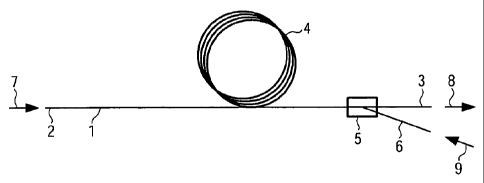
In Figure 1, an optical narrow Iinewidth Raman amplifier is shown. A silica
fiber 1 (here the
amplification fiber) is provided with an input end 2 in which input light 7
can be inputted.
Further, an output end 3 is provided through which light 8 can be output.
Between the input
CA 02711939 2010-07-08
WO 2009/090096 PCT/EP2009/000275
end 2 and the output end 3, the fiber is typically wound up to loops 4 in
order to conven-
iently store the length of the fiber.
The length of the fiber 1 between the ends 2, 3 may be between 1 and 500 m.
Approximate the output end 3, a coupler 5 is provided for coupling pumping
light 9 into the
silica fiber 1. As can be seen in Figure 1, here a backward pumping scheme is
used. The
coupler 5 is a wavelength selective coupler with which pumping light 9 can be
coupled from
the fiber end 6 into the silica fiber 1. The light which should be amplified
and which propa-
gates in the fiber 1, however, is not coupled into the fiber end 6 but is
coupled only (or al-
most only) into the fiber end 3 in order to be output due to its wavelength
being different
from the one of the pumping light.
The fiber 1 is a fiber that possibly has a nonlinearity coefficient n2 smaller
than
5 x 10-20 M2 NV and/or a Brillouin gain coefficient gs smaller than 10-10 m/W.
The fiber can
also be a polarization maintaining (PM) fiber in order to preserve the
polarization state of
the light and increase stability.
In Figure 2, a further coupler 10 is provided which is also a wavelength
selective coupler.
This coupler is able to couple the pump light 9 out of the fiber 1 into the
fiber end 11. This
coupler 10 is provided in order to avoid light to be output through the input
end 2. Such
light may disturb a light source which provides input light 7. Optionally, an
optical isolator
may be used to reduce the amount of back propagating pump or signal light to
previous
stages or the seed laser.
In other aspects, the amplifier of the Figure 2 is equal to that of Figure 1.
In Figure 3, a light source incorporating the optical amplifier of Figure 2 is
shown. A seed
light source 13 is provided which here as an example is a DFB semiconductor
laser. Such
lasers can provide sufficient light with a very narrow spectral linewidth. The
linewidth may
be less than 0.1 - 30 MHz.
In this application example the light output is guided by free space optics to
an optional fre-
quency doubling crystal 15. It is e.g. possible to use a periodically poled
nonlinear crystal.
Light 17 output from this crystal 15 can be further manipulated with
corresponding optics
CA 02711939 2012-01-11
11
It is e.g. possible to expand the beam or to focus the beam depending on the
application
purposes. It may also be coupled again into a fiber for transmission purposes.
Mirrors
and/or lenses may be used as such optics 16.
Between the seed light source 13 and the optical Raman fiber amplifier 20, an
optical
isolator may be provided. This in order to protect the seed light source 13
from the light
reflected back into the seed light source.
Further, as can be seen in Figure 3, a pump light source 14 is used. This may
also be a
high power semiconductor or fiber laser. Such pump lasers have at least 10 W
optical
pump power but may have powers of more than 20, 30, 40 or 50 Watt.
In the preferred embodiment of the invention, the seed light source 13 is a
light source
which provides 10 mW at a wavelength of 1178 nm. The pump laser 14 has a power
of
40 Watt and provides light at a centre wavelength of 1120 nm. The light 18
output from
the amplifier 20 may have a power of 2 to 25 Watt and a linewidth with a full
width at half
maximum (FWHM) of less than 10 MHz, in some cases less than 500 MHz.
The optical fiber 1 has a length of approximately 1-350 m.
Item 15 in this preferred embodiment is a frequency doubling crystal such that
the light
output from the crystal 17 has a wavelength of 589 nm. This light corresponds
to the
yellow emission D-line of sodium. With such light it is therefore possible to
excite sodium
or carry out spectral analysis with this wavelength. The excitation of sodium
can be used
for creating an artificial light source in a sodium rich atmosphere layer
approximately 90
km above ground. Such an artificial light source can be used for adjusting
adaptive
optics in astronomy. It can also be created for atomic spectroscopy or for the
medical
treatment such as treatment of (skin) cancer.
For spectroscopic purposes, the light source 13 may be a tunable light source
(with a
tunable wavelength). Since the gain of the optical amplifier 20 is provided in
a certain
wavelength range, output light 18 or the output light 17 can be tuned over a
certain
wavelength range such as e.g. more than 5, 10 or 20 nm, depending on the pump
wavelength.
CA 02711939 2010-07-08
WO 2009/090096 PCT/EP2009/000275
12
In Figure 4a section 1 a of the amplification fiber 1 is wound under tension
around a mandrel
19 in order to induce stress in the fiber. The section 1 b is not stressed.
Hence the optical
and/or acoustical properties of the two fiber sections 1 a and 1 b are
slightly different, which
allows to increase the SBS threshold.
In case the fiber section 1 a is wound on the mandrel 19 without stress such
stress may be
induced by preferably (differentially) deforming the mandrel e.g. in case this
mandrel being
a piezoelectric body which can be deformed by the application of an electrical
voltage. If the
mandrel is deformed differentially, a tension gradient in the fiber will be
included.
The mandrel may also be heated in order to obtain different fiber sections 1 a
and 1 b with
different temperatures and thereby causing a temperature gradient in the
fiber. This also
allows to increase the SBS threshold. Another kind of heating may be used such
as a hous-
ing in which a section 1 a of the fiber is provided.
In Fig. 4b a case is shown where the amplification fiber 1 comprises two
different types of
fiber. One type is indicated with 1 c and the other 1 d. The fiber sections 1
c and 4d can differ
in composition, geometry, doping or the like. They are joined at position 1 e,
preferably by a
splice. Instead of two sections, like in Fig. 4b, three or more sections may
be used. Further
the length of section 1 d may by shorter than that of section 1 c, assuming
that the light to be
amplified propagates from left to right. The section 1 a in Fig. 4a may be
composed of two
sections like sections 1 c and 1 d or three or more sections of different
types of fibers. The
same applies to section 1 b in Fig. 4a. Equally a portion of section 1 c
and/or 1 d may be ex-
posed to stress or elevated or reduced temperature in comparison to other
portions as ex-
plained for Fig. 4a for the sections 1 a and 1 b.
In Figure 5, a preferred embodiment of a multi-stage optical light source is
shown. The light
source 13 provides light which is amplified in three stages 20a, 20b and 20c.
Note that
there is no upper limit to the possible number of stages. The light output
from the last stage
can ultimately be provided to a frequency doubling unit 15 and finally, to an
output optics
16.
Optical isolators are preferably provided before and/or after each
amplification stage. Here
e.g. an optical isolator may be provided before each amplification stage and a
one after the
last amplification stage.
CA 02711939 2010-07-08
WO 2009/090096 PCT/EP2009/000275
13
With this arrangement, powers of up to 30 or 40 Watt are possible and at the
same time,
having a linewidth of less than 10 MHz, but in some cases up to 1000 MHz.
According to a method of amplifying light, a fiber is selected that has a
ratio of g,/ge of more
than 0.001. This fiber is then used for a Raman optical amplifier wherein this
Raman optical
amplifier amplifies light in this fiber.