Note: Descriptions are shown in the official language in which they were submitted.
CA 02712004 2010-07-09
WO 2009/114938 PCT/CA2009/000330
SECOND ROW FRONT TUMBLE HOOK PROTECTION
BACKGROUND OF THE INVENTION
1. Field of the Invention
[00011 The invention relates to a seat assembly for an automotive vehicle, and
more particularly, to a seat assembly that is movable between a seating
position, a kneel
position, and a tumble position.
2. Description of Related Art
[00021 Certain mini-van and sport utility vehicles are provided with second
and
third row seating for supporting seat occupants above a vehicle floor. It is
common that a
seat assembly of such second and third row seating is movable between a
seating position
and a stowed or kneel position in order to increase the amount of available
cargo space
within the vehicle. As the seat assembly moves from the seating position to
the kneel
position, a seat back is folded forwardly from a generally vertical position
to a fold flat
position overlying a seat cushion. At the same time, the seat cushion is moved
forward
and downward from a raised position spaced above the floor to a lowered
position resting
along the floor. Thus, when the seat assembly is in the kneel position a back
side of the
seat back is generally horizontal and defines a load floor surface.
[00031 Alternatively, it is common that a second or third row seat assembly is
movable between the seating position and a tumble position in order to provide
access to
an area behind the seat assembly. In order to move the seat assembly from the
seating
position to the tumble position, the seat back is first folded forwardly from
the generally
vertical position to the fold flat position overlying the seat cushion. Next,
the seat
assembly is rotated about a pivot point at a lower front edge of the seat
cushion
approximately ninety degrees (90 ) until the seat back and seat cushion are
substantially
upright. In the tumble position a rearward end of the seat cushion is
positioned above the
forward end of the seat cushion.
[00041 It is desirable to provide a seat assembly that moves between a seating
position and a kneel position and also moves between the kneel position and a
tumble
position. It is also desirable to provide a seat assembly that moves between a
seating
1
CA 02712004 2010-07-09
WO 2009/114938 PCT/CA2009/000330
position and a kneel position about a first pivot and moves between the kneel
position and
a tumble position about a second pivot.
SUMMARY OF THE INVENTION
[0005] According to one aspect of the invention, a seat assembly includes a
seat
cushion extending between forward and rearward ends and a seat back pivotally
coupled
to the rearward end of the seat cushion. A front leg is pivotally coupled
between the
forward end of the seat cushion and the floor defining an upper pivot axis and
a lower
pivot axis. The seat cushion is movable between a generally horizontal seating
position, a
generally horizontal kneel position that is disposed forward and downward of
the seating
position, and a generally vertical tumble position wherein the rearward end of
the seat
cushion is disposed above the forward end. A front link extends between an
upper end
pivotally coupled to the forward end of the seat cushion and a lower end
having a hook
that is adapted for selective engagement with a striker mounted to the floor.
A seat back
bracket extends between an upper portion and a lower portion. The upper
portion is
operatively coupled to the seat back for allowing selective pivotal movement
of the seat
back between a generally upright position and a forwardly folded position. The
lower
portion is releasably coupled to the floor. The hook of the front link is
engaged with the
striker in the seating position and released from the striker in response to
moving the seat
back between the upright position and the folded position to allow pivotal
movement of
the seat cushion about the upper pivot axis between the kneel position and the
tumble
position.
BRIEF DESCRIPTION OF THE DRAWINGS
[0006] Other advantages of the present invention will be readily appreciated
as
the same becomes better understood by reference to the following detailed
description
when considered in connection with the accompanying drawings, wherein:
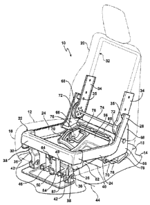
[0007] Figure 1 is a perspective view of a seat assembly in a seating position
according to the invention;
[0008] Figure 2 is a fragmentary, cross-sectional side view of the seat
assembly in
the seating position;
2
CA 02712004 2010-07-09
WO 2009/114938 PCT/CA2009/000330
[0009] Figure 3 is a fragmentary, cross-sectional perspective view of the seat
assembly in a kneel position;
[0010] Figure 4 is a fragmentary, cross-sectional side view of the seat
assembly in
the kneel position;
[0011] Figure 5 is a fragmentary, cross-sectional perspective view of the seat
assembly in a tumble position;
[0012] Figure 6 is a fragmentary, cross-sectional side view of the seat
assembly in
the tumble position;
[0013] Figure 7 is an enlarged, cross-sectional side view of a hook engaging a
forward striker when the seat assembly is in the seating position;
[0014] Figure 8 is an enlarged, cross-sectional side view of the hook and the
forward striker when the seat assembly is in the kneel position;
[0015] Figure 9 is an enlarged, cross-sectional side view of the hook
releasing
from the forward striker as the seat assembly moves between the kneel position
and the
tumble position; and
[0016] Figure 10 is an enlarged, cross-sectional side view of the hook and the
forward striker when the seat assembly is in the tumble position.
DETAILED DESCRIPTION OF THE EMBODIMENTS
[0017] Referring to the Figures, wherein like numerals indicate like or
corresponding parts throughout the several views, a seat assembly for use in
an
automotive vehicle is generally shown at 10. The seat assembly 10 includes a
seat
cushion 12 for supporting a seat occupant above a floor 14 of the vehicle. The
seat
cushion 12 extends between a forward end 16 and a rearward end 18 . The seat
assembly
also includes a seat back 20 operatively coupled to the rearward end 18 of the
seat
cushion 12 for supporting a back of the seat occupant.
[0018] The seat assembly 10 is movable between a seating position, a kneel
position, and a tumble position. The seating position is shown in Figures 1
and 2. In the
3
CA 02712004 2010-07-09
WO 2009/114938 PCT/CA2009/000330
seating position, the seat cushion 12 is in a generally horizontal raised
position that is
spaced above the floor 14 and the seat back 20 is in a generally upright or
vertical
position. The kneel position is shown in Figures 3 and 4. In the kneel
position, the seat
cushion 12 is in a generally horizontal lowered position, lying adjacent the
floor 14, and
the seat back 20 is in a forwardly folded position, overlying the seat cushion
12. The
tumble position is shown in Figures 5 and 6. In the tumble position, the seat
cushion 12 is
in a generally vertical position such that the rearward end 18 is positioned
above the
forward end 16 and the seat back 20 is in the forwardly folded position.
[00191 The seat cushion 12 includes a seat cushion frame, generally indicated
at
22, supporting a resilient contoured foam pad (not shown) that is encased by a
fabric trim
cover (not shown), as is commonly known in the vehicle seating art. The seat
cushion
frame 22 includes a pair of laterally spaced apart side members 24 that are
generally L-
shaped. Each side member 24 extends between a first end 26 adjacent the
forward end 16
of the seat cushion 12 and a second end 28 adjacent the rearward end 18 of the
seat
cushion 12. The seat cushion frame 22 also includes a front member 30
extending
between the first ends 26 of the side members 24.
[00201 The seat back 20 includes a seat back frame, generally indicated at 32,
supporting a resilient contoured foam pad (not shown) that is encased by a
fabric trim
cover (not shown), as is commonly known in the vehicle seating art. The seat
back frame
32 includes a pair of laterally spaced apart side members 34. The second end
28 of each
side member 24 of the seat cushion frame 22 is pivotally coupled to the
corresponding
side member 34 of the seat back frame 32 at 35, thereby supporting the
rearward end 18
of the seat cushion 12. The purpose of the pivotal connection between the seat
cushion
frame 22 and the seat back frame 32 will be apparent below.
[00211 A pair of laterally spaced apart outer front legs 36 are pivotally
coupled
between the forward end 16 of the seat cushion 12 and the floor 14. More
specifically,
each front leg 36 extends between an upper end 38 that is pivotally coupled to
the first
end 26 of one of the side members 24, defining a laterally extending first
pivot axis 40,
and a lower end 42 that is adapted to be pivotally coupled to the floor 14,
defining a
laterally extending second pivot axis 44.
4
CA 02712004 2010-07-09
WO 2009/114938 PCT/CA2009/000330
[0022] An inner front link 46 is disposed between the pair of spaced apart
outer
front legs 36. The inner front link 46 extends between an upper end 48 that is
pivotally
coupled to the front member 30 of the seat cushion frame 22 and a lower end 50
that
incorporates a rigid hook 52. The pivotal connection between the upper end 48
of the
inner front link 46 and the front member 30 defines a laterally extending axis
that is
coaxial with the first pivot axis 40. The hook 52 includes a forward-facing
mouth or slot
54 formed therein and a lower lip 56, best seen in Figures 7 through 10. The
hook mouth
54 is adapted for selectively engaging a forward striker 58 that is adapted to
be fixedly
secured to the floor 14. The forward striker 58 defines a laterally extending
axis that is
coaxial with the second pivot axis 44.
[0023] The forward striker 58 has a cross-sectional profile that is generally
D-
shaped. The D-shaped profile is oriented such that a rounded front portion 60
of the D
faces towards the forward end 16 of the seat cushion 12 and a straight back
portion 62 of
the D faces towards the rearward end 18 of the seat cushion 12. When the seat
assembly
is in the seating position, as shown in Figure 7, the forward striker 58 is
disposed
within the mouth 54 of the hook 52. The lower lip 56 of the hook 52 is
designed to have
a certain amount of interference with the rounded front portion 60 of the
forward striker
58 when the seat assembly 10 is in the seating position such that the hook 52
cinches or
pulls down on the inner front link 46, which in turn eliminates any looseness
in the
pivotal connections of the seat assembly 10, thereby effectively preventing
any buzz,
squeak, or rattle issues. The hook 52 holds the forward end 16 of the seat
cushion 12
down during upward load conditions. Additionally, the hook 52 transfers
forward and
downward forces imparted to the seat assembly 10 to the forward striker 58.
[0024] When the seat assembly 10 is in the kneel position, as shown in Figure
8,
the lower lip 56 of the hook 52 is disposed parallel to the straight back
portion 62 of the
forward striker 58 such that there is no interference therebetween. Thus, the
hook 52 will
release from the forward striker 58, as shown in Figure 9, to allow the seat
assembly 10 to
pivot about the first pivot axis 40 from the kneel position, shown in Figure
8, to the
tumble position, shown in Figure 10, as is described below in more detail.
[0025] A spring 64 is disposed about the pivotal connection between the upper
end 48 of the inner front link 46 and the front member 30 of the seat cushion
frame 22.
5
CA 02712004 2010-07-09
WO 2009/114938 PCT/CA2009/000330
One end of the spring 64 engages the seat cushion frame 22 and another end of
the spring
64 engages the front link 46. The spring 64 biases the seat assembly 10 from
the kneel
position to the tumble position.
[0026] A pair of laterally spaced apart seat back brackets 66 are provided for
supporting the seat back 20. Each seat back bracket 66 includes an upper
portion 68 and
a lower portion 70. A seat latch mechanism 72 is disposed between the upper
portion 68
of each seat back bracket 66 and the corresponding side member 34 of the seat
back
frame 32. The seat latch mechanisms 72 actuate between a locked state and an
unlocked
state for controlling pivotal movement of the seat back 20 relative to the
seat cushion 12.
Normally, the seat latch mechanisms 72 are in the locked state to maintain the
seat back
20 in the generally vertical position. In the unlocked state, the seat latch
mechanisms 72
allow the seat back 20 to pivot to the forwardly folded position. It is
appreciated that any
suitable latching mechanism that is capable of locking and unlocking to
control the
pivotal movement of the seat back 20 may be used without varying from the
scope of the
art. A cross-talk tube 74 extends between the seat latch mechanisms 72 for
simultaneous
actuation of the seat latch mechanisms 72 between the locked and unlocked
states and
defining a pivot axis 88 between the seat back 20 and the seat back bracket
66. It is
contemplated that only one seat latch mechanism 72 is necessary for
controlling such
pivotal movement of the seat back 20 while the pivotal connection on the other
side of the
seat assembly 10 may be a simple pivot connection between the side member 34
of the
seat back frame 32 and the upper portion 68 of the seat back bracket 66.
[0027] The lower portion 70 of each seat back bracket 66 is adapted for
releasably
securing the seat assembly 10 to the floor 14. More specifically, the lower
portion 70 of
each seat back bracket 66 includes a floor latch mechanism 76 for releasably
securing the
seat assembly 10 to the floor 14. The floor latch mechanisms 76 actuate
simultaneously
between a latched state and an unlatched state. In the latched state, the
floor latch
mechanisms 76 are engaged with rearward strikers 78 that are adapted to be
mounted to
the floor 14 for maintaining the seat assembly 10 in the seating position. The
floor latch
mechanisms 76 remain engaged with the rearward strikers 78 as the seat
assembly 10
moves between the seating position and the kneel position. In the unlatched
state, the
floor latch mechanisms 76 are disengaged from the rearward strikers 78 to
allow the seat
assembly 10 to pivot about the first pivot axis 40 between the kneel position
and the
6
CA 02712004 2010-07-09
WO 2009/114938 PCT/CA2009/000330
tumble position. It is contemplated that only one floor latch mechanism 76 is
required for
latching and unlatching the seat assembly 10 to the floor 14.
[00281 A rear support tube 80 extends laterally between the pair of spaced
apart
seat back brackets 66. Each end of the rear support tube 80 is fixedly secured
to the
corresponding seat back bracket 66, between the upper 68 and lower 70 portions
thereof.
The rear support tube 80 provides added structural stability to the seat
assembly 10.
Additionally, a drive link 82 is aligned laterally with the inner front link
46 and extends
non-linearly between the rear support tube 80 and the inner front link 46 for
providing
stability as the seat assembly 10 moves between the kneel position and the
tumble
position. More specifically, the drive link 82 extends between a forward end
84 and a
rearward end 86. The forward end 84 of the drive link 82 is pivotally coupled
to the
lower end 50 of the inner front link 46 at 87, best seen in Figures 1 and 5.
The rearward
end 86 of the drive link 82 is fixedly secured to the rear support tube 80.
The inner front
link 46 and the drive link 82 are generally linearly aligned when the seat
assembly 10 is
in the kneel position, as shown in Figure 4, and when the seat assembly 10 is
in the
tumble position, as shown in Figure 6.
[00291 In operation, beginning with the seat assembly 10 in the seating
position
shown in Figure 2, the seat latch mechanisms 72 are actuated from the locked
state to the
unlocked state such that the seat back 20 is free to pivot from the generally
upright
position to the forwardly folded position, overlying the seat cushion 12. As
the seat back
20 pivots about the pivot axis 88 and moves from the generally upright
position to the
forwardly folded position, the seat back 20 urges the seat cushion 12 forward
and
downward. More specifically, the side members 34 of the seat back frame 32
push
forwardly on the side members 24 of the seat cushion frame 22 via the pivotal
interconnecting at pivot 35 which is spaced about the pivot axis 88. As the
seat cushion
12 moves forward and downward, the outer front legs 36 and the inner front
link 46 pivot
in a counterclockwise direction (when viewed from Figure 2) about the second
pivot axis
44 to lower the seat assembly 10 downwardly adjacent to the vehicle floor 14.
The seat
assembly 10 is now in the kneel position, shown in Figures 3 and 4, with the
seat back 20
overlying the seat cushion 12 and the seat cushion 12 in the generally
horizontal lowered
position, lying adjacent the floor 14. In the kneel position, the lower lip 56
of the hook 52
is released from the rounded front portion 60 of the forward striker 58 and is
disposed
7
CA 02712004 2010-07-09
WO 2009/114938 PCT/CA2009/000330
parallel to the straight back portion 62 thereof, such that there is no
interference between
the hook 52 and the forward striker 58.
[00301 To move the seat assembly 10 from the kneel position to the tumble
position, the floor latch mechanisms 76 are actuated from the latched state to
the
unlatched state to disengage from the rearward strikers 78. The seat assembly
10 is now
free to pivot in the counterclockwise direction (when viewed from Figure 4)
about the
first pivot axis 40. More specifically, with the outer front legs 36 and inner
front link 46
resting parallel against the vehicle floor 14 and the hook 52 rotated and
released from the
striker 58, the seat assembly 10 pivots about the first pivot axis 40 until
the seat cushion
12 is in the generally vertical position with the rearward end 18 positioned
above the
forward end 16, as shown in Figures 5 and 6. The seat assembly 10 may be
returned from
the tumble position to the kneel position by simply pivoting the seat assembly
about he
first pivot axis 40 in the opposite, or clockwise direction, as shown, until
the striker 58 is
received in the slot 54 of the hook 52 and the floor latch mechanism 76 is
engaged with
the rearward strikers 78.
[00311 Finally, the seat assembly 10 may be returned from the kneel position
to
the seating position by pivoting the seat back 20 upwardly and rearwardly, in
the
clockwise direction as shown, about the pivot axis 88. The side members 34 of
the seat
back frame 32 pull on the side members 24 of the seat cushion frame 22 and
forcing the
outer front legs 36 and inner front link 46 to pivot about the second pivot
axis 44 and
raise the seat cushion 12 above the floor 14. As the seat back 20 and seat
cushion 12
return to the seating position, the hook 52 reengages with the striker 58 such
that the
lower lip 56 is interference fit and engaged with the rounded front portion 60
of the
striker 58 again providing the load support between the seat assembly 10 and
the vehicle
floor 14.
[00321 The invention has been described here in an illustrative manner, and it
is to
be understood that the terminology used is intended to be in the nature of
words of
description rather than limitation. Many modifications and variations of the
present
invention are possible in light of the above teachings. It is, therefore, to
be understood
8
CA 02712004 2010-07-09
WO 2009/114938 PCT/CA2009/000330
that within the scope of the appended claims, the invention may be practiced
other than as
specifically enumerated within the description.
9