Note: Descriptions are shown in the official language in which they were submitted.
CA 02712009 2015-10-05
=
Our Ref: 87167-24
CROSS-LINKS FOR A TRACK OF A TRACKED VEHICLE
FIELD OF THE INVENTION
The invention relates generally to tracks for tracked vehicles and, more
particularly, to cross-links
for such tracks.
BACKGROUND
Certain types of tracked vehicles, such as tractors and carriers used in
various industrial or military
applications, are propelled by a pair of tracks each comprising belts that are
interconnected by a
series of cross-links distributed longitudinally along the track.
Cross-links are typically made of metal, such as so-called "D-dent" cross-
links and "flat track"
cross-links which are forged into shape. These cross-links may be suitable
when a tracked vehicle
on which they are provided is on soft terrain (e.g., earth, mud). However, due
to the tracked
vehicle's weight, they are often unsuitable and/or unacceptable for use on
hard surfaces e.g., paved
surfaces) as they tend to damage such hard surfaces.
Some flat track cross-links have been permanently embedded in a rubber
envelope to reduce their
impact on hard surfaces. However, in view of the rubber envelope's
CA 02712009 2010-07-12
WO 2009/049416
PCT/CA2008/001832
permanent presence, these cross-links often prove inadequate in situations or
applications
where enhanced traction of metallic cross-links is desired or required, such
as on very
soft terrain.
Other flat track cross-links have been provided with urethane shoes bolted
thereon to
reduce their impact on hard surfaces. However, urethane is relatively
expensive, thus
discouraging mass production of such shoes. Furthermore, stones and other
small hard
objects typically become easily trapped in bolt holes of the urethane shoes
such that
subsequent use of a tracked vehicle equipped with such cross-links on a hard
surface can
still inflict damage on that surface. Moreover, urethane has a relatively low
friction
coefficient which can lead to poor traction capability in some applications.
Accordingly, there is a need for improvements in cross-links for tracks of
tracked
vehicles.
SUMMARY OF THE INVENTION
According to a first broad aspect, the invention provides a cross-link for a
track that
comprises belts spaced apart to accommodate a plurality of wheels of a tracked
vehicle
on which the track is mounted, the belts having a ground-facing side. The
cross-link
comprises an elongate member for mounting to the belts to interconnect the
belts, the
elongate member having a belt-engaging face contacting the belts on the ground-
facing
side when the elongate member is mounted to the belts. The cross-link also
comprises a
wheel guide comprising a pair of projections spaced apart from one another,
the
projections extending from the belt-engaging face and opposite the ground-
facing side.
The wheel guide is capable of engaging the wheels of the tracked vehicle as
the tracked
vehicle travels over the track such that, when the wheel guide engages a given
one of the
wheels, the given one of the wheels is received between the projections.
2
CA 02712009 2010-07-12
WO 2009/049416
PCT/CA2008/001832
According to a second broad aspect, the invention provides a cross-link for a
track that
comprises belts spaced apart to accommodate a plurality of wheels of a tracked
vehicle
on which the track is mounted, the belts having a ground-facing side. The
cross-link
comprises an elongate member for mounting to the belts to interconnect the
belts, the
elongate member having a belt-engaging face contacting the belts on the ground-
facing
side when the elongate member is mounted to the belts. The elongate member
defines a
channel including a bottom portion and a pair of sidewalls extending from the
bottom
portion, each of the sidewalls having a height, measured relative to the belt-
engaging
face, of at least 30 mm.
According to a third broad aspect, the invention provides a cross-link for a
track that
comprises belts spaced apart to accommodate a plurality of wheels of a tracked
vehicle
on which the track is mounted, the belts having a ground-facing side. The
cross-link
comprises an elongate member for mounting to the belts to interconnect the
belts, the
elongate member having a belt-engaging face contacting the belts on the ground-
facing
side when the elongate member is mounted to the belts. The elongate member
defines a
channel including a bottom portion and a pair of sidewalls extending from the
bottom
portion. Each of the sidewalls has a height and a thickness, the height being
measured
relative to the belt-engaging face. Each of the sidewalls has a height-to-
thickness ratio of
at least 3Ø
According to a fourth broad aspect, the invention provides a cross-link for a
track that
comprises belts spaced apart to accommodate a plurality of wheels of a tracked
vehicle
on which the track is mounted, the belts having a ground-facing side for
facing a ground
surface on which the tracked vehicle travels. The cross-link comprises an
elongate
member for mounting to the belts to interconnect the belts, the elongate
member having a
belt-engaging face contacting the belts on the ground-facing side when the
elongate
member is mounted to the belts. The elongate member defines a channel
including a
bottom portion and a pair of sidewalls extending from the bottom portion, each
of the
sidewalls having a terminating edge for engaging the ground surface to form a
region of
localized pressure on the ground surface.
3
CA 02712009 2010-07-12
WO 2009/049416
PCT/CA2008/001832
According to a fifth broad aspect, the invention provides a sole for a cross-
link of a track
that comprises belts spaced apart to accommodate a plurality of wheels of a
tracked
vehicle on which the track is mounted. The cross-link comprises an elongate
member
having a first end and a second end, the elongate member defining a channel
including a
bottom portion and a pair of sidewalls opposite one another on either side of
the bottom
portion. The sole is mountable in the channel and comprises a pair of sidewall-
engaging
surfaces for engaging the sidewalls when the sole is mounted in the channel,
the sidewall-
engaging surfaces being generally parallel to one another.
According to a sixth broad aspect, the invention provides a sole for a cross-
link of a track
that comprises belts spaced apart to accommodate a plurality of wheels of a
tracked
vehicle on which the track is mounted. The cross-link comprises an elongate
member for
mounting to the belts to interconnect the belts, the elongate member defining
a channel
including a bottom portion and a pair of sidewalls opposite one another on
either side of
the bottom portion. The sole comprises a base portion for mounting in the
channel of the
elongate member and a ground-engaging portion comprising elastomeric material
for
engaging a ground surface on which the tracked vehicle moves.
According to a seventh broad aspect, the invention provides a sole for a cross-
link of a
track that comprises belts spaced apart to accommodate a plurality of wheels
of a tracked
vehicle on which the track is mounted. The cross-link comprises an elongate
member for
mounting to the belts to interconnect the belts. The sole comprises: an inner
side for
facing the elongate member to mount the sole to the elongate member; an outer
side
opposite the inner side for engaging a ground surface on which the tracked
vehicle
moves; and a plurality of blind holes extending from the inner side without
reaching the
outer side, the sole being mountable to the elongate member via a plurality of
fasteners
received in the blind holes.
According to an eighth broad aspect, the invention provides a cross-link for a
track that
comprises belts spaced apart to accommodate a plurality of wheels of a tracked
vehicle
4
CA 02712009 2015-06-16
87167-24
on which the track is mounted, the belts having a ground-facing side. The
cross-link comprises an elongate
member for mounting to the belts to interconnect the belts, the elongate
member having a belt-engaging face
contacting the belts on the ground-facing side when the elongate member is
mounted to the belts. The
elongate member defines a channel including a bottom portion and a pair of
sidewalls opposite one another
on either side of the bottom portion. The cross-link also comprises a sole
mountable in the channel for
engaging a ground surface on which the tracked vehicle travels, the sole
comprising a pair of sidewall-
engaging surfaces for engaging the sidewalls when the sole is mounted in the
channel.
According to a ninth broad aspect, the invention provides a cross-link for a
track of a tracked vehicle, the
track comprising belts spaced apart to accommodate a plurality of wheels of
the tracked vehicle, the belts
having a ground-facing side for facing a ground surface on which the tracked
vehicle travels. The cross-link
comprises an elongate member for mounting to the belts to interconnect the
belts, the elongate member
having a belt-engaging face contacting the belts on the ground-facing side
when the elongate member is
mounted to the belts, the elongate member defining a channel, the channel
comprising a bottom portion, a
pair of sidewalls extending from the bottom portion, and a top which is open
between the sidewalls, the top of
the channel being located below the bottom portion of the channel when the
cross-link engages the ground
surface. The cross-link also comprises a wheel guide comprising a pair of
guide projections spaced apart from
one another, the wheel guide being connected to the elongate member such that,
when the elongate member is
mounted to the belts, a connection of the wheel guide and the elongate member
is located between the belts,
the guide projections projecting away from the belt-engaging face and opposite
the ground-facing side, the
wheel guide being capable of engaging the wheels of the tracked vehicle as the
tracked vehicle travels over
the track such that, when the wheel guide engages a given one of the wheels,
the given one of the wheels is
received between the guide projections.
According to a tenth broad aspect, the invention provides a cross-link for a
track of a tracked vehicle. The
track comprises belts spaced apart to accommodate a plurality of wheels of the
tracked vehicle, the belts
5
CA 02712009 2015-06-16
87167-2-1
having a ground-facing side for facing a ground surface on which the tracked
vehicle travels. The cross-link
comprises an elongate member for mounting to the belts to interconnect the
belts, the elongate member
having a belt-engaging face contacting the belts on the ground-facing side
when the elongate member is
mounted to the belts, the elongate member defining a channel, the channel
comprising a bottom portion, a
pair of sidewalls extending from the bottom portion, and a top which is open
between the sidewalls, the top of
the channel being located below the bottom portion of the channel when the
cross-link engages the ground
surface. The cross-link also comprises a wheel guide comprising a pair of
guide projections spaced apart from
one another, the wheel guide and the elongate member being connected to one
another and constituting a one-
piece component that is mountable to the belts as a unit, the guide
projections projecting away from the belt-
engaging face and opposite the ground-facing side, the wheel guide being
capable of engaging the wheels of
the tracked vehicle as the tracked vehicle travels over the track such that,
when the wheel guide engages a
given one of the wheels, the given one of the wheels is received between the
guide projections.
According to an eleventh broad aspect, the invention provides a cross-link for
a track of a tracked vehicle, the
track comprising belts spaced apart to accommodate a plurality of wheels of
the tracked vehicle, the belts
having a ground-facing side for facing a ground surface on which the tracked
vehicle travels. The cross-link
comprises an elongate member for mounting to the belts to interconnect the
belts, the elongate member
having a belt-engaging face contacting the belts on the ground-facing side
when the elongate member is
mounted to the belts, the elongate member defining a channel, the channel
comprising a bottom portion, a
pair of sidewalls extending from the bottom portion, and a top which is open
between the sidewalls, the top of
the channel being located below the bottom portion of the channel when the
cross-link engages the ground
surface, each of the sidewalls varying in height along the elongate member.
The cross-link also comprises a
wheel guide comprising a pair of guide projections spaced apart from one
another, the wheel guide being
connected to the elongate member, the guide projections projecting away from
the belt-engaging face and
opposite the ground-facing side, the wheel guide being capable of engaging the
wheels of the tracked vehicle
5a
CA 02712009 2015-06-16
87167-71
as the tracked vehicle travels over the track such that, when the wheel guide
engages a given one of the
wheels, the given one of the wheels is received between the guide projections.
These and other aspects of the invention will now become apparent to those of
ordinary skill in the art upon
review of the following description of embodiments of the invention in
conjunction with the accompanying
drawings.
BRIEF DESCRIPTION OF THE DRAWINGS
A detailed description of embodiments of the invention is provided below, by
way of example only, with
reference to the accompanying drawings, in which:
Figures 1 A and 1B respectively show a side view and a front view of an
example of a tracked vehicle
comprising a pair of tracks each comprising a plurality of cross-links in
accordance with an embodiment of
the invention;
Figure 2 shows one of the tracks arranged in an endless path around a
plurality of wheels of the tracked
vehicle;
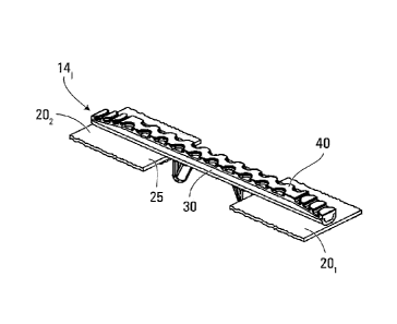
Figures 3 and 4 show different perspective views of one of the cross-links;
Figures 5 and 6 respectively show a front view and a side view of the cross-
link shown in Figures 3 and 4;
5b
CA 02712009 2010-07-12
WO 2009/049416
PCT/CA2008/001832
Figures 7 and 8 show different perspective views of an elongate member of the
cross-link
shown in Figures 3 and 4;
Figures 9 to 12 respectively show a front view, a top view, a bottom view and
a side view
of the elongate member shown in Figures 7 and 8;
Figures 13 and 14 show different perspective views of a sole of the cross-link
shown in
Figures 3 and 4;
Figures 15 to 18 respectively show a front view, a top view, a bottom view and
a side
view of the sole shown in Figures 13 and 14; and
Figure 19 shows a front cross-sectional view of the sole shown in Figures 13
and 14.
It is to be expressly understood that the description and drawings are only
for the purpose
of illustrating certain embodiments of the invention and are an aid for
understanding.
They are not intended to be a definition of the limits of the invention.
DETAILED DESCRIPTION OF EMBODIMENTS
Figures lA and 1B show a tracked vehicle 10 comprising a pair of tracks 121,
122 in
accordance with an embodiment of the invention. The tracked vehicle 10
comprises a
prime mover (e.g., an internal combustion engine) in a driving relationship
with a pair of
drive wheels 181, 182 (in this case, sprockets) each driving a respective one
of the tracks
121, 122 to propel the tracked vehicle 10 on a ground surface. As it is driven
by the
respective one of the drive wheels 181, 182, each of the tracks 121, 122 moves
in an
endless path around that drive wheel as well as a respective one of a pair of
idler wheels
191, 192 (in this case, sprockets) and a respective one of two sets of support
wheels 2114-
6
CA 02712009 2010-07-12
WO 2009/049416
PCT/CA2008/001832
2114, 212_1-212_4 of the tracked vehicle 10. The tracked vehicle 10 can be
used in various
industrial, military and/or other applications over various types of terrain.
As shown in Figure 2, in this embodiment, each track 12j (j = 1 or 2)
comprises a pair of
belts 201, 202 spaced apart from one another to accommodate the drive wheel
18j, the
idler wheel 19j and the support wheels 21.0-244 of the tracked vehicle 10. In
addition,
the track 12j comprises a series of cross-links 141-14N distributed
longitudinally along the
track 12j and extending transversally to interconnect the belts 201, 202.
Each of the belts 201, 202 has an inner side 24 facing the wheels 18j, 19j,
241-244 and
defining an inner area 15 of the track 12j in which these wheels are located.
Each of the
belts 201, 202 also has an outer, ground-facing side 25 opposite the inner
side 24 and
facing the ground surface on which the tracked vehicle 10 travels. In this
embodiment,
each of the belts 201, 202 comprises a continuous length of rubber closed to
form the belt.
In other embodiments, the belts 201, 202 may have various other constructions.
For
example, each of the belts 201, 202 may comprise a plurality of parts (e.g.,
rubber and/or
metallic sections) interconnected to one another to foim the belt. Also, while
in this
embodiment the track 12j comprises the two belts 201, 202, in other
embodiments, the
track 12j may comprise three or more such belts.
The cross-links 141-14N interconnect the belts 201, 202 and interact with the
wheels 18j,
19j, 241-21j4 as the track 12j moves in the endless path around these wheels.
In
particular, the cross-links 141-14N interact with the drive wheel 18j to cause
the track 12j
to be driven by the drive wheel 18j. More specifically, in this case, as the
drive wheel 18j
rotates, individual ones of the cross-links 141-14N engage recesses in the
drive wheel 18j
which causes the track 12j to be driven in the endless path around the wheels
18j, 19j, 21j_
1-4_4. In addition, as the track 12j moves around the endless path, individual
ones of the
cross-links 141-14N located on a lower run of the track 12j engage the ground
surface and
thus contribute to traction of the tracked vehicle 10 on the ground surface.
7
CA 02712009 2010-07-12
WO 2009/049416
PCT/CA2008/001832
With additional reference to Figures 3 to 19, in this embodiment, each cross-
link 14i (1 <
i < N) comprises an elongate member 30, a sole 40, and a pair of backing parts
501, 502.
As further discussed below, the sole 40 can be used when the tracked vehicle
10 is to
travel on a hard surface (e.g., a paved surface) in order to minimize an
impact of the
cross-link 14i on that surface. When the tracked vehicle 10 is to travel on a
soft surface
(e.g., mud, earth), the sole 40 can be removed to allow the elongate member 30
to
provide enhanced traction on that surface.
The elongate member 30 is configured to be mounted to the belts 201, 202 to
interconnect
the belts 201, 202. In addition, the elongate member 30 also serves to
transmit forces
resulting from rotational motion of the drive wheel 18j to the track 12j in
order to cause
motion of the track 12j.
More particularly, the elongate member 30 comprises a first end 311, a second
end 312
and a central portion 32 therebetween. The central portion 32 of the elongate
member 30
comes into contact with and engages the drive wheel 18j, which applies force
to the
cross-link 14i and causes motion of the track 12j in the same general
direction as the
rotational direction of the drive wheel 18i.
The elongate member 30 comprises a belt-engaging face 33 that is in contact
with the
ground-facing side 25 of the belts 201, 202, when the elongate member 30 is
mounted to
the belts 201, 202. In this embodiment, the belt-engaging face 33 is mainly
flat, which
may allow the weight of the tracked vehicle 10 to be distributed across the
entire elongate
member 30, providing the tracked vehicle 10 with a generally low ground
pressure that
may prove advantageous on certain ground surfaces.
The elongate member 30 also comprises a bottom portion 34 and a pair of
sidewalls 36r,
362 that lie opposite to one another on either side of the bottom portion 34
to create a
channel 35. As further discussed later on, the channel 35 helps to receive and
retain the
sole 40 when the sole 40 is used as part of the cross-link 14i.
8
CA 02712009 2010-07-12
WO 2009/049416
PCT/CA2008/001832
The bottom portion 34 comprises a sole-engaging surface 37 that extends from
the first
end 311 to the second end 312 of the elongate member 30 and that is in contact
with the
sole 40 when the sole 40 is used as part of the cross-link 14i. In this case,
the sole-
engaging surface 37 is generally flat such that, as the sole 40 contacts the
sole-engaging
surface 37 when mounted in the channel 35, there is a planar interface (i.e.,
contact points
lying in a common plane) between the sole 40 and the bottom portion 34 from
the first
end 311 to the second end 312 of the elongate member 30, which may allow a
more
uniform distribution of forces when the tracked vehicle 10 travels.
A plurality of holes 731-736 pass through the bottom portion 34 to receive
fasteners that
allow mounting of the elongate member 30 to the belts 201, 202. More
particularly, in this
embodiment, the holes 731-736 are divided equally between two (2) sets. Each
set is
located in one lateral portion of the elongate member 30, so that a first set
with the holes
731-733 is located in a first lateral portion proximate the first end 31i,
while a second set
with the holes 734-736 is located in a second lateral portion proximate the
second end 312.
In other embodiments, the elongate member 30 may have a different number of
holes
and/or a different arrangement of such holes.
The sidewalls 361, 362 are configured to, on the one hand, enhance retention
of the sole
40 when it is used as part of the cross-link 14i and, on the other hand,
enhance a traction
effect of the elongate member 30 in the ground surface on which the tracked
vehicle 10
travels when the sole 40 is not used. Each of the sidewalls 361, 362 extends
from the
bottom portion 34 to a terminating edge 39.
More particularly, in this embodiment, the sidewalls 361, 362 are configured
such that the
channel 35 has a substantially constant width W, from the first end 311 to the
second end
312 (while in practice there may be some slight variation in the width W, of
the channel
due to manufacturing of the elongate member 30, the width W, is substantially
constant in that it does not change from a macroscopic point of view).
Specifically, in this
30 case, the sidewalls 361, 362 have inner surfaces that are generally
parallel to one another
such that the width W, of the channel 35 is substantially constant.
Maintaining this
9
CA 02712009 2010-07-12
WO 2009/049416
PCT/CA2008/001832
substantially constant width We throughout the channel 35 along its entire
length allows
the elongate member 30 to be sturdier, facilitates its manufacturing, and
provides a better
interface with and retention of the sole 40 within the channel 35 when the
sole 40 is used
as part of the cross-link 14i.
Each of the sidewalls 361, 362 has a height H (measured from the belt-engaging
face 33 to
its terminating edge 39) providing the channel 35 with an internal height that
enhances
retention of the sole 40 therein when the sole 40 is mounted therein. The
height H of each
of the sidewalls 361, 362 also allows that sidewall to act as an aggressive
traction element
on the ground surface on which the tracked vehicle 10 travels, when the sole
40 is not
used as part of the cross-link 14i. For example, in some embodiments, the
height H of
each of the sidewalls 361, 362 may be of at least 30 mm, and in some cases 35
mm or
more, to provide such desired enhanced retention of the sole 40 when it is
used and
aggressive traction effect when the sole 40 is not used. The height H may take
on various
other values in other embodiments.
In addition to the height H of the sidewalls 361, 362, when the sole 40 is not
used as part
of the cross-link 14i, the terminating edge 39 of each sidewall engages the
ground surface
on which the tracked vehicle 10 travels to form a region of localized pressure
on the
ground surface which enhances traction of the tracked vehicle 10.
Also, in this case, the height H of the sidewalls 361, 362 is such that, when
the sole 40 is
not used as part of the cross-link 14i, any fasteners that are used to secure
the elongate
member 30 to the belts 201, 202 remain recessed within the channel 35, i.e.,
do not extend
higher than the sidewalls 361, 362. Since repeated contact between any part of
a fastener
that extended outside of the channel 35 and a hard ground surface (e.g., a
paved road or
sidewalk) could cause impact on the ground surface, the height H of the
sidewalls 361,
362 helps reduce potential damage from the cross-link 14i on such a surface.
Moreover,
such contact between any part of a fastener outside of the channel 35 and a
hard ground
surface could also cause unnecessary wear to and decrease operational life of
such
CA 02712009 2010-07-12
WO 2009/049416
PCT/CA2008/001832
fasteners, and thus the height H of the sidewalls 361, 362 also helps to
extend the
operational life of the fasteners when the sole 40 is not used as part of the
cross-link 14.
In this embodiment, the sidewalls 361, 362 decrease in height proximate the
first end 311
and the second end 312 of the elongate member 30. That is, each of the
sidewalls 361, 362
has a first tapering end portion leading to the first end 311 and a second
tapering end
portion leading to the second end 312. These tapering end portions can
facilitate turning
of the cross-link 14i when the tracked vehicle 10 and the track 12i turn.
Thus, in this and
other embodiments where the sidewalls 361, 362 vary in height along their
length, the
height H of each of the sidewalls 361, 362 can be taken as a maximum height of
that
sidewall along its length. Also, although in this embodiment both of the
sidewalls 361,
362 have the same height H, in some embodiments, the sidewalls 361, 362 may
have
different heights H.
Each of the sidewalls 361, 362 also has a thickness T (taken as its average
thickness along
its height H) which provides sufficient strength and rigidity to that sidewall
to allow it
properly retain the sole 40 when the sole 40 is mounted in the channel 35 and
to allow it
to withstand forces exerted thereon while acting as a traction element when
the sole 40 is
not used as part of the cross-link 14i. For example, in some embodiments, the
thickness T
of each of the sidewalls 361, 362 may be of 7.5 mm, and in some cases of at
least 9.5 mm,
to provide such desired enhanced retention of the sole 40 when it is used and
aggressive
traction effect when the sole 40 is not used. The thickness T may take on
various other
values in other embodiments. Also, while in this embodiment both of the
sidewalls 361,
362 have the same thickness T, in other embodiments, the sidewalls 361, 362
may have
different thicknesses T.
The height H and the thickness T of each of the sidewalls 361, 362 can thus be
selected to
allow the sidewalls 361, 362 to both enhance retention of the sole 40 when it
is used as
part of the cross-link 14i and act as an aggressive traction element when the
sole 40 is not
used as part of the cross-link 14i. For example, each of the sidewalls 361,
362 may have a
height-to-thickness ratio H/T of at least 3.0, and in some cases 3.5 or more,
to provide
11
CA 02712009 2010-07-12
WO 2009/049416
PCT/CA2008/001832
such desired enhanced retention of the sole 40 when it is used and aggressive
traction
effect when the sole 40 is not used, while maintaining sufficient strength and
rigidity.
In this embodiment, the elongate member 30, including the bottom portion 34
and the
sidewalls 361, 362, is created by stamping, in this case bending, a single
piece of material
to faun the elongate member 30. More particularly, in this embodiment, the
single piece
of material is a flat piece of metal, in this case high-strength steel, which
is bent into
shape. Various bending techniques, involving plastic deformation of the single
piece of
metal about a linear axis with little or no change in its surface area, are
well known can
be used for this process. These bending techniques can facilitate
manufacturing of the
elongate member 30 and allow proper formation of the sidewalls 361, 362 with a
height-
to-thickness H/T ratio as described above.
While in this embodiment the elongate member 30 comprises a single metallic
component that is formed and shaped through a stamping process, in other
embodiments,
the elongate member 30 may be produced using various other processes and may
comprise a plurality of components that are interconnected to one another,
such as
through welding, and that are made of the same material or different material.
For
example, in some embodiments, the sidewalls 361, 362 and the bottom portion 34
may
each be produced separately and then welded together to form the elongate
member 30.
With continued reference to Figures 1 A to 19, in this embodiment, the cross-
link 14i
comprises a wheel guide 60 to engage individual ones of the wheels 18j, 19j,
21j1-244 as
the track 12j moves in the endless path around these wheels. The wheel guide
60
comprises a pair of projections 621, 622 that are spaced apart from one
another and that
extend from the belt-engaging face 33 and opposite the ground-facing side 25,
i.e., from
the belt-engaging face 33 towards the inner area 15 of the track 12j.
As the track 12j moves along its endless path, each of the wheels 18j, 19j,
21H-21j-4
passes through the wheel guide 60, and in particular, between the projections
621, 622 that
are located on either side of these wheels. The projections 621, 622 can
interact with the
12
CA 02712009 2010-07-12
WO 2009/049416
PCT/CA2008/001832
wheels 18j, 19j, 21j_1-21j,4 to keep the cross-link 14j centered by opposing
any lateral
movement outside of a space between these projections. As a result, the
projections 621,
622 help to laterally guide the track 12j as it moves along its endless path.
In this embodiment, when viewed from a front or rear of the elongate member
30, each of
the projections 621, 622 has a triangular shape, in this case resembling a
right-angle
triangle, with a wheel-facing face 63 that faces individual ones of the wheels
18j, 19j, 21j_
1-244 as the track 12j moves along its endless path. The wheel-facing face 63
of each of
the projections 621, 622 lies at an obtuse angle relative to the belt-engaging
face 33, which
can help center the elongate member 30 (and therefore the cross-link 14) as it
comes into
contact with any of the wheels 18j, 19j, 2 4.1-21Ø. More specifically, any
lateral motion
of the elongate member 30 towards outside of the space between the projections
621, 622
will be counteracted when the wheel-facing face 63 of one of the projections
621, 622
comes into contact with one of the wheels 18j, 19j, 21.0-2 li.4, thus guiding
the elongate
member 30 back towards a center region of the space between the projections
621, 622.
Through these components, the track 12j can thus remain laterally centered
between the
projections 621, 622 and so remain on its endless path.
While in this embodiment the projections 621, 622 are configured as right-
angled
triangles, in other embodiments, the projections 621, 622 may have various
other shapes.
For example, in some embodiments, the projections 621, 622 may be configured
as non-
right-angled triangles (e.g., isosceles or equilateral triangles). Also, in
some
embodiments, the wheel-facing face 63 may define an arc that approximates a
profile of
the wheels 18j, 19j, 2 1j..1-21J-4.
In this embodiment, the projections 621, 622 are made of metallic material, in
this case
4140 high-strength steel, and are secured to the elongate member 30 by welding
them to
the belt-engaging face 33. In other embodiments, the projections 621, 622 may
be made of
various other materials and/or may be secured to the elongate member 30 in
various other
ways, such as via nut and bolt fasteners. In yet other embodiments, the
projections 621,
622 may be integrally formed with the elongate member 30.
13
CA 02712009 2010-07-12
WO 2009/049416
PCT/CA2008/001832
With continued reference to Figures 1A to 19, the sole 40 can be mounted to
the elongate
member 30 when the tracked vehicle 10 is to travel on a hard surface (e.g., a
paved
surface) in order to minimize an impact of the cross-link 14i on that surface.
More
particularly, the sole 40 comprises an inner side 42 for facing the elongate
member 30 to
mount the sole 40 to the elongate member 30 and an outer side 44 opposite the
inner side
42 for engaging the ground surface on which the tracked vehicle 10 moves. In
this
embodiment, the sole 40 is mounted to the elongate member 30 via a plurality
of
fasteners 411-416 extending from the inner side 42 to the elongate member 30.
The sole 40 comprises a base portion 46 that is mountable within the channel
35 of the
elongate member 30 and a ground-engaging portion 48 for engaging the ground
surface
on which the tracked vehicle 10 travels. In this case, certain sections of the
ground-
engaging portion 48 (e.g., extremities corresponding to the first end 311 and
the second
end 312 of the elongate member 30) may not always engage the ground surface,
but may
rather only come into contact with the ground surface in situations where the
tracked
vehicle 10 is resting on an incline and/or a soft surface (such as mud) where
the elongate
member 30 and/or the sole 40 are partially submerged.
More particularly, in this embodiment, the base portion 46 of the sole 40
comprises a pair
of sidewall-engaging surfaces 471, 472 for engaging the sidewalls 361, 362 of
the elongate
member 30 when the sole 40 is mounted in the channel 35. Thus, in this case,
the
sidewall-engaging surfaces 471, 472 are generally parallel to one another and
separated by
a distance corresponding to the substantially constant width We of the channel
35 to
allow the base portion 46 of the sole 40 to fit within the channel 35. When
the base
portion 46 is mounted within the channel 35, the sidewall-engaging surfaces
471, 472
contact the sidewalls 361, 362 (and in this case the sole-engaging surface 37)
of the
elongate member 30, which helps retains the sole 40 in the channel 35 when the
cross-
link 14i is subjected to forces as the tracked vehicle 10 moves on the ground
surface.
14
CA 02712009 2010-07-12
WO 2009/049416
PCT/CA2008/001832
Also, in this embodiment, the ground-engaging portion 48 comprises elastomeric
material
for engaging the ground surface on which the tracked vehicle 10 moves. More
specifically, in this embodiment, the elastomeric material of the ground-
engaging portion
48 is rubber, which can be any natural, synthetic, or modified high polymer
with elastic
properties, such as acrylate rubber, acrylic rubber, acrylonitrile rubber,
acrylonitrile-
butadiene rubber or butadiene rubber. In other embodiments, any other suitable
elastomeric material may be used.
When the ground surface is hard (e.g., a paved road), the rubber of the ground-
engaging
portion 48 helps minimize effects of the cross-link 14i as it comes into
repeated contact
with the hard ground surface, while providing traction for the tracked vehicle
10 to travel
along such a surface. In fact, the rubber of the ground-engaging portion 48
enhances
traction of the sole 40 by "gripping" the ground surface on which the tracked
vehicle 10
travels, in particular when the ground surface includes one or more inclined
surfaces that
may need to be traversed, such as steep paths that run up hills or down
gullies.
In this case, the ground-engaging portion 48 comprises a tread pattern 71
which may
assist in improving traction of the tracked vehicle 10 on a variety of ground
surfaces. The
tread pattern 71 may also allow channeling of water or other liquids away from
that
section of the ground-engaging portion 48 that is in contact with a wet ground
surface,
which may improve handling of the tracked vehicle 10 under wet or adverse
weather
conditions. Also, the tread pattern 71 is configured such that it lacks spaces
in which
rocks or other hard objects could become trapped in when it contacts the
ground surface.
For its part, in this embodiment, the base portion 46 of the sole 40 is also
made of the
same elastomeric material (in this case, rubber) as that of the ground-
engaging portion
48. In fact, in this embodiment, the base portion 46 and ground-engaging
portion 48 of
the sole 40 constitute a single rubber component. The rubber of the base
portion 46 helps
in retaining the sole 40 in the channel 35.
15
CA 02712009 2010-07-12
WO 2009/049416
PCT/CA2008/001832
In other embodiments, the base portion 46 may be a component distinct from but
connected to the ground-engaging portion 48 and may be made of a material
different
than that of the ground-engaging portion 48. For example, the base portion 46
may
contain a rigid material, such as ultra-high molecular weight (UHMW) plastic
or another
rigid plastic, while the ground-engaging portion 48 may contain the
elastomeric material
and be secured to the base portion 46 through one or more fasteners (e.g.,
screws or
nuts/bolts) or some bonding technique (e.g., glue or epoxy).
When the sole 40 is used as part of the cross-link 14i, it is mounted to the
elongate
member 30 via the fasteners 411-416 that extend from its inner side 42. In
this
embodiment, the fasteners 411-416 are integrated with the sole 40. More
particularly, in
this case, the sole 40 comprises a frame member 49 which acts as an armature
on which
the rubber of the sole 40 is supported. The frame member 49, which may be made
of any
suitable rigid material (e.g., steel), also supports the fasteners 411-416,
which, for
instance, can be threaded into or welded to the frame member 49.
The frame member 49, which may be made of any suitable rigid material (e.g.,
steel),
supports the fasteners 411-416. For example, the fasteners 411-416 may be
attached to the
frame member 49 by screwing one of their ends into the frame member 49 or by
welding
one of their ends directly to the frame member 49. Alternatively, the
fasteners 411-416
may be integrally formed with the frame member 49. In any event, the fasteners
411-416
and the frame member 49 are combined in a way that allows their integration
with other
components of the sole 40.
The fasteners 411-416 are arranged on the frame member 49 in such a way that
each
fastener may be aligned with one of the holes 731-736 of the elongate member
30. More
particularly, in this case, the fasteners 411-416 are divided equally between
two (2) sets
that are located in respective lateral portions of the sole 40 to match the
two (2) sets of
holes 731-733 and 734-736 of the elongate member 30. In this way, the
fasteners 411-416
may be used to mount the sole 40 to the elongate member 30 and thus mount the
cross-
link 14i to the belts 201, 202.
16
CA 02712009 2010-07-12
WO 2009/049416
PCT/CA2008/001832
In this embodiment, the rubber used to form the base portion 46 and the ground-
engaging
portion 48 of the sole 40 is molded around the frame member 49 and the
fasteners 411-
416. In addition to facilitating manufacturing of the sole 40, this
integration of the frame
member 49 and the fasteners 411-416 with a remainder of the sole 40 (i.e..,
the base
portion 46 and the ground-engaging portion 48) help simplify and speed up
mounting and
dismounting of the sole 40 to and from the elongate member 30..
Also, in this embodiment, the outer side 44 of the sole 40 lacks holes through
which the
fasteners 411-416 are exposed when the sole 40 is mounted to the elongate
member 30.
This lack of holes on the outer side 44 of the sole 40 prevents rocks and
other objects
from being trapped in the outer side 44 of the sole 40, which could otherwise
contribute
to damaging a hard ground surface (e.g., a paved road) on which the tracked
vehicle 10
travels under the vehicle's weight.
More specifically, in this case, since a first end of each of the fasteners
411-416 is
attached to the frame member 49, around which the rubber of the sole 40 is
molded, only
a second end of each fastener is exposed. In other words, the sole 40 can be
viewed as
defining a plurality of blind holes that extend from the inner side 42 without
reaching the
outer side 44, in which are received the fasteners 411-416. As a result, when
the sole 40 is
mounted to the elongate member 30, the outer side 44 of the sole 40 lacks
holes through
which the first end of the fasteners 411-416 would otherwise be exposed. This
seamless
nature of the outer side 44 prevents rocks and other small objects from
becoming trapped
within such holes and also protects the fasteners 411-416 from damage from
such debris,
which may extend their operational life.
While in this embodiment the fasteners 411-416 are integrated with the sole
40, in other
embodiments, separate fasteners may be used to mount the sole 40 to the
elongate
member 30 (e.g., by screwing them into the base portion 46 of the sole 40 from
its inner
side 24). Also, when the sole 40 is not used as part of the cross-link 14i,
the elongate
17
CA 02712009 2010-07-12
WO 2009/049416
PCT/CA2008/001832
member 30 may be mounted to the belts 201, 202 via separate fasteners or a
frame
member similar to the frame member 49 supporting a plurality of fasteners.
With continued reference to Figures lA to 19, the backing parts 501, 502 are
configured
to be mounted to the belts 201, 202 to assist the elongate member 30 in
interconnecting
the belts 201, 202. Each of the backing parts 501, 502 has a belt-engaging
face 51 that
contacts a respective one of the belts 201, 202 on its inner side 24 when the
backing part is
mounted to that belt. Thus, when the cross-link 14j is mounted to the belts
201, 202, the
belts 201, 202 are sandwiched between the belt-engaging face 33 of the
elongate member
30 and the belt-engaging face 51 of each of backing parts 501, 502.
In this embodiment, the backing parts 501, 502 are metallic plates that may be
formed
from any suitably rigid metallic material, such as steel. Each of the parts
501, 502 is
pierced with a plurality of holes 801-803 to receive fasteners, such as the
fasteners 411-416
of the sole 40 or separate fasteners when the sole 40 is not used. In this
way, the backing
parts 501, 502 may be used to interconnect the elongate member 30 (and the
sole 40, when
used) to the belts 201, 202.
It will thus be appreciated that the cross-link 14i (and other ones of the
cross-links 14i-
14N) can conveniently be mounted to the belts 201, 202 to interconnect them. A
portion of
each of the belts 201, 202 is designed to lie between the belt-engaging face
33 of the
elongate member 30 on one side (i.e., the ground-facing side 25) and the belt-
engaging
face 51 of one of the backing parts 501, 502 on the other side (i.e., the
inner side 24).
Holes in the belts 201, 202 allow alignment of the holes 731-736 of the
elongate member
30 and the holes 801-803 of the backing parts 501, 502 that sandwich the
belts. When
suitably aligned, a fastener (e.g., 411) inserted through one of the holes 731-
736 of the
elongate member 30 emerges through the belt-engaging face 33, passes through
the
corresponding hole in the belt (201 or 202), and then emerges through the
corresponding
hole (e.g., 801) in the belt-engaging face 51.
18
CA 02712009 2010-07-12
WO 2009/049416
PCT/CA2008/001832
When the holes 731-736 of the elongate member 30 are so aligned with the holes
in the
belts 201, 202, the elongate member 30 lies transversely across the ground-
facing side 25
of each of the belts. Each of the backing parts 501, 502 lies transversely
across the inner
side 24 of one of the belts 201, 202. In this configuration, the elongate
member 30 and the
backing parts 501, 502 are appropriately aligned with the belts 201, 202. The
fasteners 411-
416 are used to attach these components together and thus form the cross-link
14i with the
sole 40 mounted thereon.
The base portion 46 of the sole 40 fits within the channel 35 of the elongate
member 30
to allow mounting of the sole 40 to the elongate member 30. Thus, when the
sole 40 is
mounted to the member 30: the sidewall-engaging surfaces 471, 472 of the sole
40 engage
the sidewalls 361, 362 of the elongate member 30; the inner side 42 of the
sole 40 comes
into contact with the flat sole-engaging surface 37 of the elongate member 30;
and each
of the fasteners 411-416 attached to the frame member 49 enclosed within the
sole 40 may
penetrate its corresponding one of the holes 731-736 of the elongate member
30.
In particular, when the sole 40 is mounted, the exposed end of each of the
fasteners 411-
416 passes through a corresponding one of the holes 731-736 of the elongate
member 30,
then passes through one or the holes of the belts 201, 202 and finally passes
through a
corresponding one of the holes 801-803 in one of the backing parts 501, 502.
Tightening
the fasteners 411-416 (e.g., through the use of a threaded nut) to a suitable
amount
sandwiches the belts 201, 202 between the backing parts 501, 502 and the
elongate member
to which the sole 40 is mounted, thereby securing the cross-link 14i to the
belts 201,
202.
While this example included the sole 40 as part of the cross-link 14i, there
may be some
situations where the sole 40 may be purposely excluded. For example, the sole
40 may be
excluded from the cross-link 14i in a situation where enhanced traction is
required, such
as when the tracked vehicle 10 must traverse a very soft ground surface, such
as
travelling through sand or mud.
19
CA 02712009 2010-07-12
WO 2009/049416
PCT/CA2008/001832
In such situations, the sole 40 may be removed from the cross-link 14, (or not
mounted
thereon to begin with) to provide the enhanced traction needed to move across
such
surfaces. To remove the sole 40, the fasteners 411-416 that are integrated
with the sole 40
(via the frame member 49) are first loosened to the point where they allow
movement,
such as by loosing and/or removing a nut from each fastener.
With the fasteners 411-416 having been loosened, the sole 40 may remain
mounted to the
elongate member 30 in the channel 35 due to engagement between the sidewall-
engaging
surfaces 471, 472 of the sole 40 and the sidewalls 361, 362 of the elongate
member 30. By
pulling on the sole 40 (on the ground-engaging portion 48) in a
perpendicularly opposite
direction to the belts 201, 202, the engagement between the base portion 46 of
the sole 40
and the channel 35 of the elongate member 30 may be removed to allow removal
of the
sole 40. As the sole 40 is removed, the fasteners 411-416 pass through the
holes 801-803 in
the backing parts 501, 502, then through the holes in the belts 201, 202, and
finally through
the holes 731-736 of the elongate member 30.
Once the sole 40 is removed, the fasteners 411-416 must be replaced with a
second set of
fasteners to keep the cross-link 14i mounted to the belts 201, 202. This
second set of
fasteners may be provided individually or via a frame member that is similar
to the frame
member 49, as mentioned previously. If fasteners in the second set of the
fasteners are
provided individually, one end of each fastener is fed through a corresponding
one of the
holes 731 - 736 of the elongate member 30, then through a corresponding one of
the holes
in the belts 201, 202, and then through a corresponding one of the holes 801-
803 in the
backing parts 501, 502, while its other end is secured within the channel 35
(e.g., via a
suitable nut). Alternatively, if the second set of fasteners is provided via a
frame member
that is similar to the frame member 49, the exposed ends of these fasteners
are first
aligned with the holes 731 - 736 in the bottom portion 34 of the elongate
member 30.
Upon insertion of the frame member into the channel 35 of the elongate member
30, the
fasteners linked to this frame member pass through the components of the cross-
link 14,
and the belts 201, 202 in a manner similar to that described above and are
suitably
tightened (e.g., through threaded nuts) to keep the belts 201, 202 sandwiched
between the
CA 02712009 2010-07-12
WO 2009/049416
PCT/CA2008/001832
backing parts 501, 502 and the elongate member 30, which keeps the cross-link
14i
mounted to the belts 201, 202 without the use of the sole 40.
It will thus be appreciated that this ability to mount and dismount the sole
40 from
elongate member 30 allows the tracked vehicle 10 to traverse a wide variety of
ground
surfaces with improved traction while minimizing impact on the traversed
surface.
Although various embodiments and examples have been presented, this was for
the
purpose of describing, but not limiting, the invention. Various modifications
and
enhancements will become apparent to those of ordinary skill in the art and
are within the
scope of the invention, which is defined by the appended claims.
21