Note: Descriptions are shown in the official language in which they were submitted.
CA 02712055 2010-07-12
WO 20091118402 PCTIEP2009/053644
METHOD FOR MEASURING THE VOLUME FLOW OF ELECTRICALLY
CONDUCTIVE LIQUIDS THROUGH A VESSEL
Description
The invention refers to a method of measurement of the volume of rate
of flow of electrical conductive liquids through a vessel according to
claim 1. The invention also refers to a respective measuring device.
The measurements of filling heights are conducted wherever the vol-
umes of liquids and the alteration of volume have to be determined. The
measurements of filling heights are usually done by electrodes, which
immerse at least partially into the liquid. The electrical conductivity or
the resistance of the liquid, which is proportional to the filling height or
the volume of the liquid, is measured by a suitable measuring device.
Such measurements are necessary in order to determine the exhaus-
tion of filter cartridges, which are used in gravitation driven filtration de-
vices.
WO 02/27280 A discloses a device using three electrodes one of which
is used.as reference electrode. The electrodes for level measurement
are configured in such a way that a measurement value sharply
changes when certain limits of the level are exceeded or fallen short of.
These leaps of the measurement values can be reliably recognized
without high demands on the accuracy of measurement.
A similar device is known from EP 1 484 097 BI which comprises at
least three electrodes, counting means and timers. The signals meas-
ured by these components are fed to an input of a microprocessor that,
on the basis of a resident programme, elaborates important data on the
life-span of the cartridge according to the amount of time passed since
CA 02712055 2010-07-12
WO 2009/118402 PCT/EP2009/053644
2
its first activation and the amount of water treated identified in terms of
closure considered important by circuit between the electrodes, and by
the ionic concentration of the pollutants, identified in terms of conductiv-
ity of the water being treated.
In case of consideration a partial filling of the vessel numerous elec-
trodes are located on growing levels in a compensation chamber within
the vessel.
This device is expensive and never even takes into consideration the
design and shape of the vessel. Exact measurements of volume require
intermediate measurements of the filling height taking into account the
vessel shape. Usually, the vessel has any design so that the correlation
between filling height and liquid volume doesn't follow a simple mathe-
matical formula.
Most of the measuring devices ignore vessel shape so that the determi-
nation of life-span of the filter cartridge is not as precise as it should be.
US 4,724,705 A relates to a fuel measurement device and particularly a
device for determining for quantity of a fuel in a fuel tank. The fuel level
indicator includes a hollow housing, a coded wafer, a short circuit wafer
including a wafer substrate, a buoyant member and a continuity bridge.
The coded wafer is made of a dielectric, ceramic material and extends
along the interior length of the hollow housing. An electrically conduc-
tive wire strand having a known resistance per unit length is wound
about the coded wafer to define a "pattern of resistance" representative
of the contour of the interior wall of the fuel tank. The manufacturing of
the fuel level indicator is quite an effort, in particular for manufacturing
of the coded wafer.
CA 02712055 2010-07-12
WO 2009/118402 PCT/EP2009/053644
3
DE 10 2005 035 045 Al discloses a measuring device comprising a
measuring element that includes at least one electrode the area of
which increases in an exponential manner from one and to the other.
The benefit of this invention is the fact that the value of electrical con-
ductivity and the absolute value of the liquid level in the vessel need not
to be known, if there is an exponential correlation between the measur-
ing values and the volume of the liquid in the vessel.
The objective of the invention is to provide a method and a measuring
device which allows to measure the volume of rate of flow through a
vessel in a more precise and easy manner. D
This objective is solved by a method, which is characterized in that
the measured values x are measured in time intervals and that the re-
spective filling volumes V0 are determined by comparison of the respec-
tive measured values x with calibration measured values xR of at least
one reference table comprising at least calibration measured values xR
and filling volumes Vo belonging to them, and that the volume VD of the
rate of flow is determined from the filling volumes VD over a time period,
wherein the at least one reference table is constructed by means of
calibration measurements using several liquid samples, which have dif-
ferent p-values and different filling heights h in the vessel. J~
The time period, in which the filling volumes Vo are measured, can be a
predetermined time period. In case that the method of measurement is
applied f. e. to a filtration device, the starting time can be the time when
f. e. a new filter cartridge is put into the device. In this case the time pe-
riod is limited f. e. by the life time of the cartridge or the time period
until
the cartridge is replaced.
The benefit of the invention is that simple electrodes can be used and
that the parameter p and the shape of the vessel, which both influence
CA 02712055 2010-07-12
WO 2009/118402 PCTIEP20091053644
4
the results of the measurements of the filling height h and therefore of
the filling volume V0, can be taken into consideration by constructing at
least one reference table.
The calibration measured values XR contained in this reference table
are constructed for each shape of the vessel and are deposited in the
memory of the electrical conductivity measuring device. The mechanical
features of the measuring device, in particular the shape and technical
details of the electrodes, need not to be adapted to the shape of the
vessel when one type of measuring device is used in different vessels.
-~ It is only necessary to provide the respective table or tables containing
the specific values which reflect the shape and the different types of
liquid flowing through the vessel. If the vessels are mass-products only,
the construction of at least of one table for each type of vessel is nec-
essary and one and the same measuring device can be used without
mechanical adaption.
The values of the liquid volume in the vessel can be measured in a very
precise manner, because not only parameter p but also the shape of
the vessel are taken into consideration when the calibration measure-
ments are conducted.
The at least one reference table can be deposited in a memory of the
measuring device.
One reference table can be sufficient, if for example the influence of
parameter p on the measurement of the filling height h is less or not
significant and/or there is for example a linear relationship between Vo
and the shape of the vessel. In these cases the correlation between x
and h and therefore between x and Vo can be unique.
CA 02712055 2010-07-12
WO 2009/118402 PCT/EP2009/053644
However, in cases, where the influence of parameter p or where more
than one parameter p is getting significant on the result, more than one
reference table is needed. The same is true when there is a non-linear
correlation between x and VO. All these facts result in ambiguous val-
ues, if only one table is used. This problem can be overcome by con-
struction of more than one table, for example two or three reference
tables in order to get unique and precise results.
It is preferred that a first reference measured value x1 is measured at
least once during said time period.
This first reference measured value x, is used to determine at least one
of the parameters p of the liquid, which f. e. can be the hardness of wa-
ter. It is further preferred that the first reference measured value x1 is
measured only once at the beginning of a filling procedure starting from
an empty vessel. Before the beginning of filling the measuring device is
in the status "waiting for water" so that at the first contact of the elec-
trodes with the liquid results in the measurement of the first reference
measured value x1. After this measurement the measuring device
switches into the status "height measurement" so that all following
measured values are classified as measured values x.
D
The first reference measured value x, is stored and can be used for the
calibration of the measured values x until the vessel is empty again and
the next filling of the vessel has been started. According to this em-
bodiment it is preferred that said first reference measured value xi is
measured by the same two measuring electrodes which are used for
the measuring of measured values x.
According to another embodiment it is preferred that this first reference
measured value x1 is measured every time when the measured value x
is measured. In this case the measuring device does not distinguish
CA 02712055 2010-07-12
WO 2009/118402 PCT/EP2009/053644
6
between the very first measurement at the beginning of the filling pro-
cedure and the following measurements. This kind of measurement is
more precise however it needs a reference electrode. The first refer-
ence measured value x1 is measured by this reference electrode and
one of the measuring electrodes which are used for the measurements
of measured values x.
As illustrated in connection with the measuring device, this electrode is
shielded with the exception of the lower surface.
It is preferred that a first reference table is constructed which contains
the calibration first reference measured values X1R, which are corre-
sponding to the first reference measured value x,, and the respective
values of parameter p belonging to them. It is also preferred to con-
struct a second reference table which at least contains the calibration
measured values xR, the values of parameter p and the respective filling
heights h belonging to them and to construct a third reference table
which takes into consideration the shape of the vessel and which con-
tains the filling heights h and the respective filling volumes Vo belonging
to them.
It is preferred to determine the value of parameter p at least from the
first reference measured value x, by comparison with the first reference
table.
It is also preferred to determine the filling height h at least from the
measured value x and the values of the parameter p by comparison
with the values of the second reference table.
The respective filling volume Vo can be determined from the filling
height h by comparison with the values of the third reference table.
CA 02712055 2010-07-12
WO 2009/118402 PCT/EP2009/053644
7
Starting with the measurement of the measured values x it is a step by
step procedure to achieve the filling volume VD.
It is preferred to use a first calibrated value l1 which is a function of x
and x1 instead of x only. Therefore, in the reference tables I and 2 XR is
replaced by the corresponding first calibrated value 1i. Preferably, the
first calibrated value 11 is I1 = xi / x.
It is preferred that a second reference measured value x2 is measured
at least once during said time period.
This second reference measured value x2 can be measured at the be-
ginning of the filling procedure started from an empty vessel or it can be
measured every time when the measured value x is measured.
This second reference measured value x2 is preferably measured by
means of a reference circuit of the electrical conductivity measuring de-
vice.
In order to consider temperature drifts of the electronic part of the
measuring device it is preferred to refer and therefore to calibrate the
value xs to the second reference measured value x2. Preferably, such a D
second calibrated value 12 is 12 = x2/xl.
This step contributes to the improvement of the precision of the volume
measurement.
Therefore it is preferred to introduce 12 into the first reference table,
which contains I1, 12 and the parameter p. From both values I1 and 12 the
parameter p can be determined in a more precise manner.
CA 02712055 2010-07-12
WO 2009/118402 PCT/EP2009/053644
8
Although 11 = x, I x and 12 = x2 / xt, both values can be multiplied by a
suitable factor to achieve figures which can be handled easier. It is pre-
ferred to achieve values without decimal point.
The values of the parameter p can be determined from the values 11
and 12 by comparison with values of the first reference table.
The filling height h can be determined from the values of parameter p
and the first calibrated value li by comparison with values of the second
reference table.
Although the claimed method can be used to measure the volume of
the flow rate of various liquids, the measurement of water is preferred.
In case of water, the parameter p is the hardness H, which is the most
important property of water that affects the electrical conductivity. Its
possible to use another property of the liquid as parameter p, f. e. the
pollution of the water.
In a preferred embodiment the measured values x, x, and/or x2 are a
time values.
The electrical conductivity measuring device comprises an electrical
circuit which preferably comprises a capacitor means. The charging
and/or the discharging time of this capacitor means can be used as
measured values x, because it depends from the filling height of the
liquid in the vessel.
The measured values x are measured at least once per second. It is
preferred to measure the measured values x at least five times per sec-
ond.
CA 02712055 2010-07-12
WO 2009/118402 PCT/EP2009/053644
9
It is preferred to measure not only the measured value x but also x, and
x2 and to calculate l1 and 12. This can be done by an appropriate elec-
tronic device which is part of the electrical conductivity measuring de-
vice.
In a preferred embodiment the changes AV of the filling volumes Vo are
determined and the volume VD of the flow rate is determined from the
volume changes AV.
It is preferred to determine the volume VD of the flow rate from the re-
spective volume increase- This embodiment is preferred if the filling of
the vessel happens more rapidly than the draining off of the liquid, f. e.
faster by a factor of at least 10. It is assumed that the amount of liquid
which is filled in is equivalent to the amount that is drained off.
The volume VD of the flow rate is compared with a volume Vim,., which
is the maximum volume of the liquid, that is characterized by the at
least one parameter p and which volume is allowed to flow through the
filter device which is arranged downstream of the vessel. This filter de-
vice contains at least one filter medium. The exhaustion of the filter me-
dium is indicated, when Vmax is reached.
The maximum volume Vmax depends on the at least one parameter p,
for example on the hardness H in case of water. Therefore, a fourth ref-
erence table is recommended which contains the respective volume
Vmax for various values of parameter p. Vm,, can be determined by
comparison of the values of the parameter p with the corresponding
values deposited in the fourth reference table.
The exhaustion of the filter medium can be indicated acoustically and/or
optically.
CA 02712055 2010-07-12
WO 2009/118402 PCT/EP2009/053644
It is another possibility to indicate remaining volumes acoustically
and/or optically until the exhaustion of the filter medium is reached.
It is preferred to use a filter cartridge as a filtering device. This filter
car-
tridge can be arranged in the outlet of the vessel.
The objective of the invention is also solved with a measuring device for
the determination of the volume VD of the flow rate of electrical conduc-
tive liquids through a vessel wherein the filling heights h are changing in
the vertical direction and wherein the vessel comprises an inlet and an
outlet, and a conductivity measuring device which comprises an evalua-
tion unit and at least two measuring electrodes wherein the measuring
electrodes are located in the vessel and are connected to the evaluation
unit, wherein at least one measured value x is measured by the elec-
trodes characterized in that the evaluation unit is configured for the
deposition of at least one reference table comprising at least calibration
measured values XR and filling volumes Vo belonging to them and for
comparison of the measured values x of the conductivity measuring
device with the calibration measured values XR of the at least one refer-
ence table and for the determination of the volume Vo of the flow rate
from the filling volumes Vo.
Both measuring electrodes preferably extend over the total filling height
of the vessel wherein these measuring electrodes are not shielded over
the total filling height.
As explained in connection with the claimed method, a reference elec-
trode is provided which is arranged near both measuring electrodes.
This reference electrode is preferably shielded with the exception of its
lower surface.
. CA 02712055 2010-07-12
WO 20091118402 PCTIEP2009/053644
11
The electrodes can comprise a constant cross-section along the total
length. The benefit of these simple electrodes is the fact that the elec-
trodes can be cut from a long wire in order to adapt the electrodes to
the height of the vessel. It is not necessary to manufacture specific
electrodes for each type of vessel.
The evaluation unit preferably comprises a capacitor means. As illus-
trated in connection with the claimed method the charging and/or dis-
charging time of the capacitor means is the measured value x.
The evaluation unit preferably comprises a reference circuit having a J
reference resistor Ro.
Furthermore, it is preferred that the measuring device encompasses an
indicator unit which can be an optical or an acoustical unit-
In order to simplify the manufacturing of the measuring device, the elec-
trodes can be combined to a measuring stick. It is preferred that the
measuring stick is integrated into the wall of the vessel.
The vessel can be a feeding hopper of a water filtration device.
A preferred use of the measuring device is the exhaustion measuring
device for filter cartridges.
The indicator unit can preferably indicate the time of change of the filter
cartridge.
Preferred embodiments are illustrated in connection with the following
drawings:
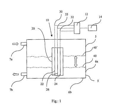
Fig. 1 shows a schematic view of a measuring device,
CA 02712055 2010-07-12
WO 2009/118402 PCT/EP2009/053644
12
Fig. 2 shows the measuring stick comprising three electrodes,
Fig. 3 shows a vertical cross-section of a jug containing a vessel
and measuring device,
Fig. 4 shows the electrical circuit of the measuring device,
Fig. 5 shows a diagram how the measured value x is calculated
from the charging and discharging time of the capacitor
means,
Fig. 6 shows a vertical cross section of a vessel
Fig. 7 table 1,
Fig. 8 table 1 a,
Fig. 9 table 2,
Fig. 10 table 3 and
Fig. 11 table 4.
In fig. 1 there is shown a simplified vessel 5 which is filled with water up
to the water level 40. The vessel comprises a bottom wall 6b and a
sidewall 5 having an inlet 7a and an outlet 7b. Inside the vessel there is
located a measuring stick 20 which is approximately 5 mm above the
bottom wall 6b of vessel 5.
The measuring stick comprises two measuring electrodes 22, 24 (first
embodiment) and an additional reference electrode 26 (second em-
bodiment) which is located between the measuring electrodes 22 and
24. The three electrodes are connected via electrical connections 30,
32, 33 to an evaluation unit 12 which is connected to an indication unit
14, If the water level 40 rises up to water level 40', the volume change
is measured by the measuring device.
In fig, 2 and in the following fig. 3 and 4 it is illustrated the second em-
bodiment wherein the measuring electrodes 22 and 24 are unshielded
and the reference electrode 26 is shielded by a shield 27 whereas the
lower surface 28 is unshielded.
CA 02712055 2010-07-12
WO 2009/118402 PCT1EP2009/0 3644
13
In fig. 3 a water filtration device 1 is shown which comprises a jug 2
having a grip 3 and a feeding hopper which forms the vessel 5. In the
outlet of vessel 5 there is located a filter cartridge 50. The measuring
device 10 is located inside vessel 5 and the electrodes are connected to
the evaluation unit and to the indication unit which are arranged in the
lid 4. Water to be filtered 8 is filled into vessel 5. After the filtration by
the filter cartridge 50 the filtered water 9 flows into and is collected in
the tug 2.
In fig. 4 the three electrodes 22, 24 and 26 are connected to an electri-
cal circuit which contains a reference circuit 15 in which a reference
resistor 17 is arranged. Furthermore, there is a capacitor means 16
which is charged and discharged by switching the switches 18 and 19.
In fig. 5 the diagram that corresponds to the charging and discharging
of the capacitor means 16 is shown. In a first step the capacitor means
is brought to a well defined voltage value by charging and discharging
it. After time T3 is reached, the measuring procedure is started. The ca-
pacitor means is charged until 1.5 Volts are reached and then it is dis-
charged until the starting value of 0.75 Volts is reached. The sum of the
charging time T4 and the discharging time T5 is used as measured value ID
X.
Example-
The method of determination of rate of flow of water is depicted in detail
in connection with figures 6 to 11.
A vessel 5 (figure 6) having a bottom wall 6b and a side wall 6a com-
prises an inlet 7a and an outlet 7b, wherein the outlet is located in the
CA 02712055 2010-07-12
WO 2009/118402 PCT/EP2009/053644
14
bottom wall 6b. The vessel 5 is open at the upper side which forms the
inlet 7a.
The shape of the vessel is defined by side wall 6a which are inclined
upwards like a cone. At the left hand sight of vessel 5 there is indicated
the height h in mm and the corresponding filling volume V0. There is a
non-linear correlation between height h and volume V because the vol-
ume increases in a non-linear manner when the water level rises.
The correlation between h and VO is deposited in table 3 (figure 10).
In order to measure the hardness value H there are two options.
According to the first embodiment (only two electrodes) both measuring
electrodes 22, 24 are used to measure the hardness value.
When the vessel 5 is empty and the water is filled in, the rising water
level contacts the lower tips of both electrodes so that a first measure-
ment can be done. Since the measuring device is in the status "waiting
for water" the first measurement is the measurement of the first refer-
ence measured value xi. After this measurement all further measure-
ments concern the measurement of the measured values x.
This single first reference measured value x1 is used to determine the
hardness value H by comparison with the values of table 1 (first table).
If xi = 20 pS/cm, the hardness value H is 3. This value x, is stored in
the memory of the measuring device and during the further filling proc-
ess only values x are measured.
According to the second embodiment (two measuring electrodes and a
reference electrode) only one measuring electrode 22 or 24 and the
reference electrode 26 are used to measure the hardness value.
CA 02712055 2010-07-12
WO 2009/118402 PCT/EP2009/053644
When the vessel 5 is empty and the water is filled in, the rising water
level contacts the lower tips of both electrodes so that first measure-
ments can be done.
One first measurement concerns the measurement of x between elec-
trodes 22, 24 and another first measurement concerns the measure-
ment of x1 between f. e. electrode 22 and the reference electrode 26.
The hardness value H is determined by comparison x, with the values
of table 1.
I)
During the following filling process always both values x and x, are
measured, whereby a change of the hardness value can be detected by
a change of the values xi.
However, the measured value x might be falsified by various parame-
ters. Therefore it is recommended to normalize the measured value x
by the reference measurement of the reference electrode 26. The first
calibrated value 11 = xi/x is for example 15.
However, the electronic components of the evaluation unit 12 might
also falsify the measured values. Therefore, it is recommended the first
reference measured value x, by a measurement of the reference resis-
tor R0 located in the reference circuit 15 in order to determine the sec-
ond reference measured value x2. This second calibration results in the
second calibrated value 12, which is 12 = x2/x..
An improved first reference table 1 a is shown in figure 8.
If for example 12 = 2500, this value can be found in different rows of ta-
ble 1 a. However I1 =15 is known so that the corresponding hardness
value H must be 3.
CA 02712055 2010-07-12
WO 2009/118402 PCT/EP2009/053644
16
In the next step the actual height h has to be found which corresponds
to the measured value x.
In a second reference table (table 2, figure 9) which contains the hard-
ness H and the 11 - values, h = 50 mm can be found.
If the calibration is not conducted and therefore 11 is not determined,
table 2 contains the measured values x instead of 11.
Since the shape and the volume of the vessel doesn't correlate in a lin-
ear manner with the filling height, it is necessary to look into a third ref-
erence table (table 3, figure 10), where the corresponding volume value
Vo can be found. Since the measurement of value x starts from the be-
ginning of the filling procedure, the difference volumes AV have to be
added. When reaching h = 50 mm the total volume is 1,2 1, which is the
sum of the difference values AV in table 3 up to the height value h = 50
mm.
In order to determine the life-span of the filter cartridge, a fourth table
(table 4, figure 11) is used. The hardness value is 3 which corresponds
to Vmax = 1201.
All tables have been prepared for a specific filtration device and have
been deposited in the memory in the measuring device.
It is preferred to determine the volume values and to compare them with
the Vmax value every time when the value x is measured. The value x is
preferably measured five times a second, so that a high precision can
be achieved.
CA 02712055 2010-07-12
WO 2009/118402 PCT/EP2009/053644
17
List of reference numbers
1 water filtration device
2 jug
3 grip
4 lid
vessel
6a side wall
6b bottom wall
7a inlet
7b outlet
8 water to be filtered
9 filtered water
measuring device
12 evaluation unit
14 indication unit
reference circuit
16 capacitor means
17 reference resistor
18 switch
19 switch
measuring stick D
22 measuring electrode
24 measuring electrode
26 reference electrode
27 shield
28 lower surface
electrical connection
32 electrical connection
33 electrical connection
CA 02712055 2010-07-12
WO 2009/118402 PCTIEP2009/053644
18
40 water level
40' water level
50 filter cartridge
x measured value
XR calibration measured value (in the table)
x1 first reference measured value
x3R calibration first reference measured value
x2 second reference measured value
x2R calibration second reference measured value
VO filling volume
VD volume of the flow-rate of the electrical conductive liquid
I1 first calibrated value
12 second calibrated value
h filling height
Vmax maximum volume of the liquid characterized by a parame-
ter p that is allowed to flow through a filter device