Note: Descriptions are shown in the official language in which they were submitted.
CA 02712188 2015-08-13
WO 2009/091738
PCT/US2009/030854
FILING DEVICE Nwrig RETRACTABLE TABS
FIELD OF INVENTION
The present invention relates to a filing device and more particularly to a
filing
device having a retractable tab.
BACKGROUND OF THE INVENTION
File folders having tabs extending from an edge of the folder are known. Tabs
can be formed integrally with the folder such that they are permanent
extensions of the folder,
or provided as separate members that can be attached to the folder.
It is also known to provide movable tabs on folders. For example, U.S. Patent
No. 5,996,881 discloses a convertible folder with a tab that is secured to a
pair of elongate
slots such that it is movable up and down the slots between a display position
and an out-of-
way position. The top portion of the tab is substantially wider than the
distance between the
slots such that the top portion remains protruding on top of and out of plane
from the folder in
the out-of-way position. U.S. Patent No. 5,341,982 discloses file folder
having a tab that is
placed at an outer corner of the folder. The tab is secured to the folder by a
rivet such that it
can be rotated 90 to extend from either edge of the corner. U.S. Publication
No.
2007/0119082 discloses a folder tab that includes a fixed base and a movable
title portion,
such that the title portion can be raised and lowered within the base. The
title portion remains
protruding from the folder even in the lowered position.
There is a need for a filing system having improved retractable tabs.
SUMMARY OF THE INVENTION
The invention relates to a filing system and components thereof, i.e., filing
devices such as folders, binders, or dividers, having retractable tabs. The
filing device
comprises a first panel having a first edge and a tab holder disposed
proximate the edge of the
panel. The tab holder is configured for receiving and retaining a tab therein
and defines at
least one opening. In an embodiment, the tab holder comprises tab holding
members that are
configured to cooperatively hold a tab between adjacent members. The tab
holder can be
configured for holding any suitable number of tabs.
- 1 -
CA 02712188 2010-07-14
WO 2009/091738
PCT/US2009/030854
The filing device includes a retractable tab having a display portion and a
mounting portion. The mounting portion is mounted in the tab holder such that
the tab is
movable between a retracted position, in which the display portion is disposed
substantially
in plane with the panel and tab holder, and an extended position, in which the
display portion
extends from the tab opening beyond the first edge of the panel and an
extended position and
wherein the tab holder is associated with the mounting portion to retain the
mounting portion
from being released therefrom. The mounting portion is preferably wider than
the tab
opening for preventing the tab from being removed from the tab holder.
Preferably, the display portion extends substantially no further than first
edge
of the panel in the retracted position. For example, the tab can have
substantially the same
height as the tab holder such that the uppermost edge of the tab is generally
flush with the
first edge in the retracted position.
In an embodiment, the tab can be retained in the extended position by friction
against moving to the retracted position. In such embodiment, the display
portion can be
configured to be no wider than the opening of the tab holder such that the
display portion can
slide into and out of the opening. Alternatively, the display portion can be
wider than the tab
opening for retaining the tab in the extended position, the display portion
being resiliently
deformable for fitting through the opening when moved between the retracted
and extended
positions.
The display portion can include locking members, such as projections or
protrusions, for reversibly engaging the tab holder in the extended and/or
retracted positions.
Such locking members "lock" the tab in place, preferably by audibly and/or
tactilely snapping
into place, so that the tab does not freely slide into and out of the tab
holder.
For example, the display portion can be wider than the tab opening in a
lateral
direction measured along the panel edge to provide locking members for
retaining the tab in
the extended and retracted positions. The display portion can include lateral
protrusions, and
the tab can further define notches between the protrusions and the mounting
portion for
receiving lateral edges of the tab holder at the opening when the tab is in
the extended
position.
Alternatively or additionally, the display portion can extend out of plane
with
respect to the panel for retaining the tab in the extended position. The
display portion can be
resiliently biased with respect to the mounting portion for bending out of
plane with respect
to the panel for resisting retraction from the extended position, or
resiliently biased out of
- 2 -
CA 02712188 2010-07-14
WO 2009/091738
PCT/US2009/030854
plane for increasing friction against the tab holder in the retracted position
that resists
movement of the tab toward the extended position.
In a further embodiment, the tab can comprise one or more stiffening members
that extend from the display portion proximate the mounting portion to further
retain the tab
in the selected position.
The filing device can include a plurality of tab holders disposed along the
panel edge and a plurality of retractable tabs associated with the tab holders
for selectively
extending at least one of the display portions at a desired location along the
panel edge.
Further a plurality of such filing devices can be provided in a filing system,
such that
different ones of the devices can selectively have the tabs in the extended
positions at
different locations along the panel edges for organizing the filing system.
BRIEF DESCRIPTION OF THE DRAWINGS
The invention will be better understood with reference to the attached
drawings illustrating preferred embodiments, wherein:
FIGS. 1 and 2 are perspective views of a folder and retractable tabs
constructed according to an embodiment of the invention;
FIGS. 3 is a side view of a folder and a retractable tab constructed according
to another embodiment of the invention;
FIGS. 4A and 4B are perspective and side views of a folder and a retractable
tab constructed according to another embodiment of the invention; and
FIG. 5 is a perspective view of a folder and retractable tabs according
another
embodiment of the invention.
DETAILED DESCRIPTION OF THE PREFERRED EMBODIMENTS
While the present retractable tabs are described in connection with folders in
the following description, it will be appreciated that any suitable filing
device, such as
binders, dividers, index cards, notebooks, and the like, can include the
retractable tabs
according to the invention. Preferably, the tabs are employed on an article
that holds or
divides a stack or stacks of paper. Further, a plurality of same or different
types of filing
devices with retractable tabs can be included in a filing system, such that
different ones of the
devices can selectively have tabs extended at different positions along the
edges thereof for
organizing the filing system.
Referring to FIGS. 1 and 2, a folder 10 having retractable tabs 50 is shown.
The folder 10 includes a pair of flat cover panels 12,14 that are preferably
rectangular. The
folder 10 can have any suitable size and shape, and can be made of any
suitable material. For
- 3 -
CA 02712188 2010-07-14
WO 2009/091738
PCT/US2009/030854
example, the folder 10 can have a conventional file folder size and can be
formed from a
single blank of substantially rectangular paperboard material that is folded
along a fold line
16 to hingedly define the panels 12,14, such that the panels 12,14 are
interconnected to each
other along the fold line 16.
The folder 10 includes one or more tab holders 30 proximate an edge of the
folder 10, such as the edge disposed opposite from the spine 16 that hingedly
connects the
cover panels 12,14. Tab holders can also be provided at the opposite edge 19,
such that the
folder 10 includes tab holders on both panels 12,14. The tab holder 30
includes one or more
openings 32 into which tabs can be provided. The tab holder 30 can include a
single unit that
extends substantially the entire edge 18, or can include multiple tab holding
units positioned
along the edge 18.
In a preferred embodiment, the tab holder 30 is formed by folding an edge
portion 20 of the panel 12 and adhesively securing the folded portion 20 to
preferably the
interior of the panel 12. In other embodiments, separate tab holder structures
can be attached
to the folder 10, for example by gluing. The tab holder 30 preferably does not
add
significantly thickness or bulk of the folder 10. Only a portion of the folded
portion 20, such
as the peripheral edge 22, is preferably adhesively attached to the panel 12
such that the
unattached folded portion and the panel 12 form a tab holding cavity 34
therebetween. In
other embodiments, other portions of the folded portion 20, such as between
openings 32, can
be attached to the panel 12, to separate individual cavities 34. The cavity 34
is dimensioned
to receive the tab 50 therein. Preferably, the height 36 of the cavity 34
substantially
corresponds to the height 63 of the tab 50. In other embodiments, the height
36 of the cavity
34 can be greater or less than the height 63 of the tab 50.
A tab opening 32 for receiving the tab 50, such as a slot, is defined in the
tab
holder 30, for example by removing a portion of the folded portion 20 and/or
panel 12
proximate the edge 18. The openings 32 can be formed by removing a portion of
either the
folded portion 20 or panel 12 or both. The opening can be formed before or
after the folded
portion 20 and panel 12 are attached.
The opening 32 is preferably sized and configured to facilitate grasping of
the
tab 50 therein by hand to extend the tab 50. The opening can have any suitable
configuration,
such as trapezoidal configuration shown in FIGS. 1-2, rectangular
configurations as shown in
FIGS. 3-4, or other configurations such as curved configurations. The folder
10 can include
any suitable number of openings. For example, the number of openings can be
selected
based on the desired folder and tab configuration and sizes of the folder and
tabs. A
- 4 -
CA 02712188 2010-07-14
WO 2009/091738
PCT/US2009/030854
conventional manila folder or a hanging folder having a width of about 12 to
15 inches can
include 1 to 7 openings along an edge of the folder, preferably 2 to 5
openings, and more
preferably 3 or 4 openings, for holding the corresponding number of
retractable tabs. If
smaller tabs are used, more openings and retractable tabs are also possible.
When the folder
10 includes multiple openings 32, the openings 32 are preferably separated by
a suitable
distance such that adjacent tabs 50 do not contact each other. In an example,
adjacent ends of
adjacent openings are separated by at least about 1 inch. Preferably, adjacent
openings are
separated by between about 1 to 4 inches.
The tab 50 is configured to be movable between a retracted position, wherein
the tab 50 does not extend beyond the edge 18 of the folder 10, as shown by
the far right tab
in FIG. 1, and an extended position, wherein the tab 50 extends beyond the
edge 18, as shown
by the middle tab in FIG. 1. In the retracted position, the top edge 58 of the
tab 50 is
preferably generally flush with or is below the edge 18. In this way, the tab
50 is hidden
from view by the facing cover 14 when the folder 10 is closed, or does not
optically break the
visual edge of panel 12. The tab 50 is movable between the retracted and
extended positions
by sliding it upwardly and downwardly within the tab holder 30, such as by
pulling and
pushing by hand. When the tab 50 is pulled or pushed to a height, the tab 50
remains in that
position due to the fraction fit between the tab 50 and the tab holder 30.
Thus, the tab 50 can
be moved to any desired height, confined only by the height 36 of the tab
holder 30.
The tab 50 comprises a display portion 52 and a mounting portion 54. The
mounting portion 54 is configured to be received in the opening 32, and
retained within the
tab holder 30. In an embodiment, the mounting portion 54 includes side flanges
56. When
the tab 50 is pulled out into the fully extended position, the side flanges 56
abut against the
closed portion of the edge 18 to prevent the tab 50 from slipping out of the
opening 32. Thus,
the tab can be pulled up until the side flanges 56 contact the edge 18 and
pushed down until
the mounting portion 54 contacts the bottom of the tab holding cavity 36.
Preferably, the
depth 36 of cavity 34 is sufficiently small and the height 65 and width 61 of
the flanges 56
are configured to prevent the tab 50 from being twisted out of the opening 32
without
bending, to help avoid unintended removal of the mounting portion 56 from the
opening 32.
The display portion 52 can have any suitable width 67, which can be selected
based on, for example, the size of the particular filing system, size of the
opening of the tab
holder, and desired use. For a conventional manila folder or hanging folder of
a width up to
about 15 inches, the display portion 52 can have a width 67 of preferably at
least about a
quarter inch, more preferably at least about a half inch, and still more
preferably at least about
- 5 -
CA 02712188 2010-07-14
WO 2009/091738
PCT/US2009/030854
1 inch, and at most about 12 inches, preferably at most about 10 inches. In
preferred
examples, the width 67 is about 1 to 3 or 5 inches.
Preferably, the width 61 of the mounting portion 54 is wider than the width 38
of the opening 32. For example, the width 61 can be at least about a quarter
or third of an inch
and preferably at least about a half inch wider than the width 38 of the
opening 32. The width
61 is at most about 3 inches and preferably at most about 2 inches wider than
the width 38 of
the opening 32. In a preferred example, the width 61 is about a half to 1 inch
wider than the
width 38 of the opening 32. The height 63 of the tab 50 is preferably no wider
than the height
36 of the tab holding cavity 34, and more preferably substantially corresponds
to the height 36
of the cavity 34. The tab 50 preferably has a height 63 of at least about a
half inch, more
preferably at least about 3/4 inches, and at most about 3 inches, more
preferably at most about
2 inches. In preferred examples, the tab has a height of about 3/4 to 2
inches. Preferably, the
height 65 of the flange 56 and the height 63 of the tab 50 has a ratio of
about 1:10 to about
7:10, and more preferably about 1:5 to 1:2. Other suitable dimensions can be
used in
alternative embodiments.
The mounting portion 54 preferably has sufficient width 61 and height 65 to
prevent the tab 50 from being removed from the tab holder 30 by merely
twisting the tab
within the tab holder without deforming the tab, for example by flexing the
side flanges 56
toward each other. In the embodiment shown in FIG. 2, the diagonal distance
201 of the
mounting portion 54 is sufficiently greater than the diagonal distance 203, so
that the tab 50
can be inserted into the opening 32 by deforming the tab 50 but cannot be
taken out of the tab
holder 30 by rotating the tab 50 because flange 56 of the tab 50 will first
abut either the lower
end or upper end of the height 36 of the cavity 34 and block further rotation.
The display portion 52 is configured to be at least partially received in the
opening 32 in the retracted position and to extend beyond the edge 18 in the
extended
position. Preferably, the display portion 52 is sized and configured for
sliding into and out of
the opening 32 by pushing and pulling by hand. In preferred embodiments, the
display
portion 52 is no wider than the width 38 of the opening 32 so that it can
slide in and out of the
opening 32 with ease. For example, the display portion 58 can have a generally
rectangular
configuration with substantially uniform width as shown in FIG. 1, or can have
downwardly
inclined side edges as shown in FIG. 2. In other embodiments, at least a
portion of the
display portion 52 can be wider than the opening 32 for retaining the tab 50
in the extended
position. In such embodiments, the display portion can be resiliently
deformable for fitting
through the opening 32 when moved between the retracted and extended
positions.
- 6 -
CA 02712188 2010-07-14
WO 2009/091738 PCT/US2009/030854
Preferably, the display portion and the mounting portion are substantially
continuous as shown in FIGS. 1 and 2, i.e., extends from one to the other
without any visible
division or disruption therebetween.
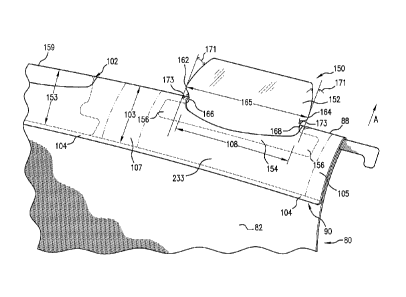
Referring to FIGS. 3-5, a hanging folder 80 having retractable tabs
130,230,150 are shown. Similar to folder 10, folder 80 can have any suitable
size and shape.
Preferably, the folder 80 includes a pair of flat, generally rectangular
folder panels that are
formed from a single blank of substantially rectangular paperboard material
and are
interconnected to each other along a fold line.
The folder 80 shown in FIGS. 3-5 includes one or more tab holders 90 that
have a similar configuration as the tab holder 30 shown in FIGS. 1-2 and
define a tab holder
cavity 233. For example, the tab holder 90 can be formed by folding an edge
portion of the
panel 82 over itself and attaching the bottom edge 104 of the folded portion
to the interior of
the panel 82. Optionally, lateral edges of the folded portion 105 and the area
107 between
openings 102 can also be attached to the panel 82. Preferably, the cavity 233
has a height
103 that is at least as high as the height 153 of the tab 150, such that the
uppermost edge 159
of the tab is generally flush with or is lower than the edge 88 of the folder
80 in the retracted
position. The opening 102 of the folder 80 is preferably configured such that
the tab holder
90 covers at least a portion of, and more preferably substantially the entire,
mounting portion
134,234,154. In other embodiments, the opening 102 can extend the entire, or
substantially
the entire, height of the tab holder 90.
Similar to the tabs 50 shown in FIGS. 1-2, the tabs 130,230,150 shown in
FIGS. 3-5 each comprise a display portion 132,232,152 and a mounting portion
134,234,154,
and is mounted on the tab holder 90 such that it is movable between a
retracted position and
an extended position. The tabs 130,230,150 can be formed by folding a piece of
material
over itself to receive an insert, such as a label, therebetween.
In preferred embodiments, the display portion 132,232,152 comprises locking
members to help retain the tab 130,230,150 in place in the retracted and
extended positions,
and to prevent the tab 130,230,150 from freely sliding between positions. The
locking
members reversibly engage with the tab holder 90 in the retracted position,
and are released
from the tab holder 90 in the extended position to provide a detectible
feedback when the tab
130,230,150 is extended or retracted. Preferably, the locking members "lock"
the tab in place
by audibly and/or tactilely snapping into place, so that the tab does not
freely slide into and
out of the tab holder. In addition to snapping into place, tactile feedback
can also be provided
by noticeably changing the force required to continue to move the tab
130,230,150, such as
- 7 -
CA 02712188 2010-07-14
WO 2009/091738
PCT/US2009/030854
by friction of the tab 130,230,150 against the tab holder 90 that changes
depending on the
degree of extension or retraction of the tab 130,230,150.
For example, the display portion 132,232,152 can be wider than the tab
opening 102,108 in a lateral direction measured along the panel edge 88 to
provide locking
members for retaining the tab 130,230,150 in the extended and retracted
positions. The
locking members can comprise lateral protrusions 162,164 shown in FIG. 5, such
that the
end-to-end distance 165 between the protrusions 162,164 is slightly wider than
the width 108
of the opening 102. The distance 165 should preferably be only slightly wider
than the width
108, such that the protrusions 162,164 can be inserted into and removed from
the tab holder
90 with little force. The user would insert the protrusions 162,164 into the
opening 102 by,
for example, flexing the edges together. The protrusions 162,164 are
preferably resiliently
deformable for fitting through the opening 102 when moved between the extended
and
retracted positions. When the tab 150 is pulled out to the extended position,
the protrusions
162,164 are released and "pop out" from the opening 102. In preferred
examples, the
distance 165 is at least about 0.1 inches and preferably at least about a
quarter inch wider than
the width 108, and is at most about 1 1/2 inches and preferably at most about
1 inch wider
than the width 108. More preferably, the distance 165 is about a quarter to
about a half inch
wider than the width 108. When the filing system includes multiple tabs 150
with protrusions
162,164, adjacent tabs 150 are preferably spaced such that protrusions of
adjacent tabs do not
contact each other.
The tab 150 can additionally include notches 166,168 at either side of the
display portion 152, between the protrusions 162,164 and the mounting portion
154, for
receiving lateral edges of the tab holder 90 at the opening 102 when the tab
150 is in the
extended position. The notches 166,168 thus further facilitate grasping and
moving the tab
150 between the extended and retracted positions. The notches 166,168 can be
provided with
any tab configuration, and are especially advantageous with tabs having
lateral protrusions,
such as the tab 150 in FIG. 5.
In preferred embodiments, both the display portion 152 and notches 166,168
are sloped shallowly enough to enable the tab 150 to be pulled or pushed to
extend or retract
across the tab holder 90 opening without having to bend the tab 150 using
fingers. As such,
the notches 166,168 also provide a tactile feedback between the retracted and
extended
positions by snapping or popping into and out of the tab holder 90 when a
sufficient force or
pressure is exerted thereto to pass them through the opening 102. Besides the
notches
- 8 -
CA 02712188 2010-07-14
WO 2009/091738
PCT/US2009/030854
166,168, any other suitable features can be used to provide such snapping or
popping effect
between positions.
Preferably, the display portion 152 and notches 166,168 are sloped at angles
171,173, respectively, with respect to the extension/retraction direction A.
The slope 171 of
the display portion 152 is preferably at least about 3 , more preferably at
least about 5 , and
at most about 600, more preferably at most about 40 , with respect to the
extension/retraction
direction A. The slope 173 of the notches 166,168 is preferably at least about
5 , more
preferably at least about 7 , and at most about 700, more preferably at most
about 50 , with
respect to the extension/retraction direction A. In preferred embodiments, the
slope 171 is
about 5 to 20 , and the slope 173 is about 15 to 45 ,with respect to the
extension/retraction
direction A.
In the embodiment shown in FIG. 3, the tab 130 can have substantially
uniform width that substantially corresponds to the width of the opening, and
includes
locking members that comprise transversely projecting, curved edges 142,144
that extend out
of plane with respect to the panel 82 in the extended position to resist
retraction of the tab 130
to the retracted position. When the tab 130 is in the retracted position, the
projecting edges
142,144 are pressed against the panel 82 by the tab holder 90, and are
resiliently biased out of
plane for increasing friction against the tab holder 90 that resists movement
of the tab 90
toward the extended position. When the tab 130 is pulled out to the extended
position, the
edges 142,144 "pop out" from the tab holder 90 and extend out of plane with
respect to the
panel 82 for retaining the tab 130 in the extended position.
In another embodiment shown in FIGS. 4A and 4B, the tab 230 has a display
portion 232 that is resiliently biased with respect to the mounting portion
234 for bending out
of plane with respect to the panel 82 for resisting retraction from the
extended position.
Preferably, the display portion 232 is resiliently biased by the tab holder 90
to be
substantially within the plane of the panel 82 and contained within the cavity
233 of the tab
holder 90 for increasing friction against the tab holder 90 when in the
retracted position to
resist movement of the tab 230 toward the extended position. The tab 230 can
further include
one or more stiffening members to help maintain a resilient bend 235, such as
stiffening ribs
236, which can be debossed, embossed, or otherwise provided on the display
portion 232
proximate mounting portion 234. Preferably, the stiffening ribs 236 extend
proximate the
intersection between the display portion 232 and mounting portion 234. In each
of these
embodiments, the tab 130,230 is deformed when retracted to frictionally engage
the inside of
the tab holder 90 for being retained in the retracted position, and since the
display portion
- 9 -
CA 02712188 2010-07-14
WO 2009/091738
PCT/US2009/030854
132,232 is out-of-plane, the tab 130,230 would also be retained in place in
the extended
position.
In this way, the locking members shown in FIGS. 3-5 provide detectible
feedback when the tab 130,230,150 is pulled or pushed between extended and
retracted
positions, or otherwise help retain the tab 130,230,150 in the chosen
position. In other
embodiments, the tab 130,230,150 can include combinations of locking members,
for
example, both lateral and transverse protrusions.
The retractable tab according to the invention is preferably sufficiently
rigid to
resist bending and sufficiently resilient to withstand handling by the user,
but is sufficiently
flexible to allow insertion into the tab holder. Preferred materials includes
paper (e.g.,
paperboard), lightweight plastic (e.g., thermoplastic such as polypropylene
and PVC), and
metal. The tab can be configured to be directly written onto, or to hold an
insert therein. For
example, the tab can comprise two layers of material, such as a piece of
material that is
folded over itself along an edge thereof, to receive a label therebetween.
When configured to
hold an insert, the tab should preferably be substantially transparent. The
tab can be colored
as desired. When the filing system includes multiple tabs, individual tabs can
have the same
color or different colors.
The tab is preferably formed as a unitary construction, and can be made with
conventional equipment, such as conventional die cutters. For example, the tab
can comprise
a single piece of material. Alternatively, the tab can be formed as two or
more layers, for
example by folding a piece of material along an edge thereof and joining or
otherwise
holding together an overlapping portion of the material. In other embodiments,
the tab can
comprise separate parts, e.g., separate mounting and display portions, that
are joined together.
The tab can have any suitable configuration, such as rectangular, trapezoidal,
circular, or rounded configurations. The tab can be substantially flat, or can
be configured to
project out of plane.
The present retractable tabs provide many advantages over conventional tabs.
For example, when a filing system includes multiple retractable tabs, the user
can easily
select and adjust the desired tab configuration by selectively extending and
displaying desired
number of tabs at desired locations. The tabs are easily moved between
extended and
retracted positions by pulling and pushing by hand, but are held in place. In
embodiments
including locking members, the detectible feedback provided by locking members
further
ensure that the tabs stay in place in the selected position.
- 10 -
CA 02712188 2015-08-13
WO 2009/091738
PCT/US2009/030854
As used herein, the term "about" should generally be understood to refer to
both the corresponding number and a range of num'oers. In addition, all
numeric-al ranges
herein should be understood to include each whole integer within the range.
While
illustrative embodiments of the invention are disclosed herein, it will be
appreciated that
numerous modifications and other embodiments may be devised by those skilled
in the art.
For example, the features for the various embodiments can be used in other
embodiments.
Therefore, it will be understood that the appended claims are intended to
cover all such
modifications and embodiments that come with the scope of the present
invention.
- 11 -