Note: Descriptions are shown in the official language in which they were submitted.
CA 02712350 2010-07-15
WO 2009/093957 PCT/SE2009/000023
OPENABLE ROOF OR WALL
TECHNICAL FIELD
The present invention relates to an openable roof or an openable wall
for use in premises where it is desirable to have completely or partially
openable sections. Such a roof or wall may be used, for example, in public
premises such as restaurants, pool areas or shopping malls, but also in more
private places such as glazed balconies and atriums. The invention is not
limited, however, to these exemplifying applications.
BACKGROUND ART
An openable roof or an openable wall usually consists of two or more
panels, which are displaceable relative to each other along guide rails
between an open and a closed state. Because the panels are suspended
from guide rails there are a number of junctions and joints through which air,
moisture and dirt, such as dust and pollen, are able to penetrate. As a rule
the
moisture and dirt are caused by wind and weather, but may also be a con-
sequence of maintenance activities such as window cleaning. Moisture may
also accumulate in the form of a condensate, which is due to the natural
moisture content of the atmosphere. No matter how the moisture penetrates
into junctions and joints, it causes the formation of condensate and discolo-
ration, which affects visibility and the overall visual appearance as well as
the
material in itself in the form of corrosion and aging. Moreover, the moisture
binds dirt, which necessitates regular maintenance.
A particular area associated with the risk of air and dirt penetrating due
to wind and weather is the zone of overlap between two panels. This zone
forms an air pocket which is closed along three edge portions of the two
overlapping panels, but which opens onto the surroundings along a fourth
edge portion, and more specifically into the open air on the outside of the
roof/wall. Under windy conditions water/snow or dirt may be blown into the air
pocket, which is similar to a wind catcher. By using various seals the air and
the moisture/dirt are prevented from penetrating further between the two
panels. A sealing system of this kind is disclosed in US 5,829,204, in which
the air pocket is delimited along three edges by seals arranged between two
overlapping roofing panels.
CA 02712350 2010-07-15
WO 2009/093957 PCT/SE2009/000023
2
Yet, penetration cannot be prevented altogether, since some leakage
will always occur due to the capillary action between the individual seal and
the surface against which it seals. Furthermore, leakage occurs through the
gap that is inevitably formed between the individual seal and the surface
against which it seals as the wind blows into the air pocket. This is because
the wind causes a cyclic deflection of the upper, outermost panel relative to
the lower, inner panel in the form of a lifting motion transversely of the
latitudinal direction of the panels. The lifting motion causes a gap to form
in
the sealing surface between the two panels, through which air, moisture and
dirt may enter, thereby penetrating further into the guide rails. Once the
moisture is inside the guide rails there is no natural way for it to escape.
To
eliminate the risk of this type of wind-related deflection and moisture
penetration, the extent of the panels in the transverse direction is usually
limited and the surface instead divided into several sections. This means that
more panels and more guide rails are required, which makes the roof or wall
more expensive and less aesthetically appealing. Furthermore, it will be
appreciated that by providing tighter surfaces gains in the form of lower
heating costs for the premises can be achieved.
OBJECTS OF THE PRESENT INVENTION
The object of the present invention is to provide an openable roof or
openable wall which has an improved sealing effect with respect to air and
moisture penetration as compared with openable roofs or walls according to
prior art.
Another object is to provide a sealing effect such as to allow increased
panel widths and, thus, use of fewer panels and suspension profiles, respec-
tively, for a certain surface.
A further object is that the concept should provide a sealing effect
which is sufficiently improved to allow a reduction of the regular maintenance
activities.
SUMMARY OF THE INVENTION
To achieve at least one of the above objects and other non-stated
objects which will appear from the following description, the present
invention
relates to an openable roof or openable wall, comprising at least one section
extending along a longitudinal axis, each section comprising a plurality of
panels overlapping in pairs along said longitudinal axis, each of which
CA 02712350 2010-07-15
WO 2009/093957 PCT/SE2009/000023
3
comprises two opposite, mutually parallel longitudinal edge portions, which
extend parallel to said longitudinal axis, and a first and a second transverse
edge portion, which extend transversely of said longitudinal axis, two sus-
pension profiles extending in parallel along said longitudinal axis and com-
prising guide rails for supporting said panels, the longitudinal edge portions
being movably received in guide rails to enable opening and closing of the
section by relative displacement of the panels along the longitudinal axis of
the guide rails,
the first transverse edge portion of a superjacent panel of a pair of panels
overlapping, in the closed state of the section, the second transverse edge
portion of a subjacent panel of said pair, and
each panel on the second transverse edge portion comprising a first sealing
strip, which in its longitudinal direction comprises three sections, a first
and a
second section of which each encloses, in a direction transversely of said
longitudinal axis, a longitudinal edge portion of the panel and a third
section of
which extends between the first and the second section on the upper side of
the panel. The openable roof or wall is characterised in that each panel, on
said transverse edge portion, further comprises a second sealing strip, which
in its longitudinal direction comprises three sections, a first and a second
section of which each at least partly encloses, at least in a direction trans-
versely of said longitudinal axis, a longitudinal edge portion on the upper
side
of the panel and a third section of which extends between the first and the
second section on the upper side of the panel, the first sealing strip being
arranged closest to an outer edge of the second transverse edge portion and
the first and second sealing strip defining between them a gap, which gap
cooperates with a bottom surface of the inner longitudinal surfaces of the
guide rails to form a drainage channel along said bottom surface in the
longitudinal direction of the respective guide rail away from said first
sealing
strip.
It has been found that an openable roof or wall of this design has an
excellent sealing effect with respect to weather-related penetration of air,
moisture and dirt. It has also been found that it has an excellent capacity
for
draining off the moisture that does after all manage to penetrate, no matter
whether the moisture is in its liquid phase or its vapour phase. Tests have
shown the sealing effect to be so good that the width of the panels could be
increased without affecting the sealing effect, which allows increased section
widths and, thus, the use of fewer panels and suspension profiles, respec-
CA 02712350 2010-07-15
WO 2009/093957 PCT/SE2009/000023
4
tively, for a certain surface. The invention thus enables a more aesthetically
appealing and energy-saving openable roof or openable wall. The invention
also enables reduced heating costs.
The openable roof or wall according to the invention can be said to
have four sealing zones, which all serve as an obstacle to an incoming flow of
air and airborne moisture. The first zone consists of the air pocket that is
formed between each pair of overlapping panels. The penetrating air must
initially have sufficient kinetic energy, i.e. speed, to penetrate into this
air
pocket and reach the second sealing strip, which forms a second zone. Once
there, the air still needs sufficient kinetic energy to be able to penetrate
through the second sealing strip. On its way through the sealing strip, large
particles such as dust, pollen and sand are filtered out. The degree of
filtration
and also of energy reduction depends on the density of the sealing strip. Most
of the moisture that appears in liquid form, if any, is unable to penetrate
due
to the density of the sealing strip. Moisture in vapour form, however, is able
to
penetrate by way of diffusion. Depending on a possible wind-related de-
flection air/moisture/dirt may, of course, also be able to pass through the
opening which is formed, in this case, between the sealing strip and its
contact surface. The air/moisture/dirt that, despite the above obstacles, is
able to penetrate through the second sealing strip will enter a third zone,
which consists of the gap between the first and second sealing strips. In the
third zone more kinetic energy is lost due to the sudden increase in volume to
which the air is subjected in the gap. By now the air has lost so much kinetic
energy that it is simply not capable of penetrating through the fourth zone,
which consists of the first sealing strip. This means that, under normal
conditions, the first sealing strip will provide an almost absolute protection
against air leaking into the premises. Instead the air will spread in the gap.
And so will the moisture, no matter whether it is in liquid form or vapour
form.
Due to the reduced kinetic energy of the air, any dirt will fall to the bottom
of
the gap and remain there.
Because the first and second segments of these two sealing strips
enclose, completely and at least partly, respectively, the longitudinal edge
portions of the panel, the gap has the same extension as these two sealing
strips. The gap thus extends from the upper side of the panel, around the
longitudinal edge portions and further down on the underside of the panel. As
a result, the air and, in particular, the moisture will travel through the gap
and
down towards the underside of the panel, and more specifically onto the
CA 02712350 2010-07-15
WO 2009/093957 PCT/SE2009/000023
bottom surface that is formed on the inner longitudinal surface of the guide
rail. Moisture in liquid form, if any, will be able to flow along the guide
rail in
the drainage channel formed between said bottom surface and the underside
of the first and second sections, respectively, of the second sealing strip.
5 Moisture in vapour form, if any, will be able to either escape with the air
through the drainage channel or penetrate by way of diffusion through the
second sealing strip and its first and second sections, respectively, and
further out into the drainage channel. A seen in the direction of the lower,
transverse edge portion of the panel, the drainage channel may open into the
open air. As a result the moisture, whether in liquid form or vapour form, may
escape through the drainage channel.
In view of the above, it will be appreciated that it takes extreme wind
loads to overcome the sealing effect of the first and second sealing strips,
thereby enabling air, moisture and dirt to penetrate between the panels and
into their guide rails. The air and moisture that do after all penetrate is
allowed
to escape, in a controlled manner, through the gap and the drainage channel.
Dirt in particulate form is filtered out very efficiently by having it pass
through two zones, on one hand the air pocket between the two overlapping
panels and, on the other, the second sealing strip, before it is able to pene-
trate into inaccessible spaces such as the gap, between the panels and on
the inside of the guide rails.
In the case of an openable roof, such a roof is normally mounted at a
certain angle to a horizontal plane, which means that the suspension profiles
with their guide rails will be mounted at the same angle. This means that any
moisture/dirt that penetrates into the guide rails through gravitation will be
conveyed downwards through the drainage channel. Drainage may also take
place through the scraping motion occurring between the guide rails and the
first and second sections, respectively, of the first and second sealing
strips
as the panel is displaced relative to the guide rails for the purpose of
opening
or closing.
Said gap may comprise a recessed groove. This causes further dissi-
pation of the energy of the air that is able to penetrate into the gap through
the space between the third segment of the second seal and the surface
against which this strip is adapted to seal, i.e. the lower panel. The penetra-
ting air needs to have a certain quantity of energy, i.e. speed, to be able to
first penetrate the first zone between two overlapping panels and then pene-
trate also the second zone, which consists of the second sealing strip. The
CA 02712350 2010-07-15
WO 2009/093957 PCT/SE2009/000023
6
remaining quantity of energy is significantly reduced as it enters the third
zone, i.e. the recessed groove, since this groove represents a greater
volume.
Each panel may further comprise third sealing strips on its two
longitudinal edge portions on the upper side of the panel, which third sealing
strips are arranged to extend from the second to the first transverse edge
portion, and wherein said third sealing strips, in the second transverse edge
portion, are in contact with the second sealing strip for forming a continuous
joint with the same. In this way air, moisture and dirt are prevented from
penetrating between the guide rail and the panel transversely of the longi-
tudinal extension of the guide rail.
Moreover, each panel may comprise fourth sealing strips on its two
longitudinal edge portions on the underside of the panel, which fourth sealing
strips are arranged to extend from the second to the first transverse edge
portion, and wherein said fourth sealing strips, in the second transverse edge
portion are in contact with the first sealing strip for forming a continuous
joint
with the same.
Accordingly, on the underside of the panel the fourth sealing strip cuts
off the gap between the first and second sealing strips. This means that the
air and moisture that have accumulated in the gap and pass through it down
to the underside of panel will be prevented by this sealing strip from conti-
nuing in the longitudinal direction of the gap. Instead the air and moisture
will
travel downwards towards the first and second sections of the second sealing
strip on the underside of the panel and continue through the drainage
channel.
Each panel may further comprise fourth sealing strips on its two
longitudinal edge portions on the underside of the panel, which fourth sealing
strips are arranged to extend from the second to the first transverse edge
portion, and wherein said fourth sealing strips, in the second transverse edge
portion, are in contact with the first and the second sealing strips for
forming a
continuous joint therewith. The main purpose of these sealing strips is to
prevent air, moisture and dirt from penetrating between the guide rail and the
panel transversely of the longitudinal direction of the guide rail.
The first sealing strip may form a fluid tight seal against the inner
longitudinal surface of said guide rail and against the adjacent panel of said
panels overlapping in pairs, respectively. By this is meant a sealing effect
between the sealing strip and its contact surface which air and moisture, with
CA 02712350 2010-07-15
WO 2009/093957 PCT/SE2009/000023
7
dimensioning parameters for normal wind loads, are unable to overcome. The
first sealing strip may be made of a non diffusion tight material. Examples of
this type of material are a heavily compressed brush-type seal, a brush-type
seal comprising a film which extends in the direction of the bristles or an
extruded, flexible strip of, for instance, rubber, plastic or silicone. It
will be
appreciated that the sealing capacity is dependent not only on the choice of
material but also on parameters such as the degree of compression and the
width of the sealing strip. It is obvious to the person skilled in the art to
identify
a sealing strip that is suitable for this purpose.
The second sealing strip may form a non fluid tight seal against the
inner longitudinal surface of said guide rail and against the adjacent panel
of
said panels overlapping in pairs, respectively. By this is meant a sealing
effect
such that air and moisture, while meeting with resistance, are able to pass
either through the sealing strip or between the sealing strip and the surface
against which it seals. The second sealing strip may be made of a non
diffusion tight material. Examples of this type of material are a brush-type
seal
or a flocked sealing strip. It will be appreciated that the sealing capacity
is
dependent not only on the choice of material but also on parameters such as
the degree of compression and the width of the sealing strip. It is obvious to
the person skilled in the art to identify a sealing strip that is suitable for
this
purpose.
The third and fourth sealing strips may form a fluid tight seal against
the inner longitudinal surface of said guide rail. By this is meant a sealing
effect between the third and fourth sealing strips and their contact surface
such that air and moisture, with parameters dimensioned for normal wind
loads, are unable to penetrate. The third and fourth sealing strips may be
made of a diffusion tight material. Examples of this type of material are a
heavily compressed brush-type seal, a brush-type seal comprising a film
which extends in the direction of the bristles or an extruded, flexible strip
of,
for instance, rubber, plastic or silicone. It will be appreciated that the
sealing
capacity is dependent not only on the choice of material but also on para-
meters such as the degree of compression and the width of the sealing strip.
It is obvious to the person skilled in the art to identify a sealing strip
that is
suitable for this purpose.
The first and the second section, respectively, of the first sealing strip
may each form a sliding element adapted to cooperate with the inner
longitudinal surface of the associated guide rail during displacement of the
CA 02712350 2010-07-15
WO 2009/093957 PCT/SE2009/000023
8
panels relative to the guide rails. Owing to the flexibility of the sealing
strip the
sliding surfaces fill up the space between the panel and the inner
longitudinal
surface of the guide rail.
The second transverse edge portion may comprise grooves for
receiving said first and second sealing strips. The grooves provide what can
be described as a pre-forming of the shape of the sealing strips, since the
wall portions of said grooves will limit the lateral extent of the sealing
strips
when they abut against the surface against which they are intended to seal.
This provides a better sealing effect. The grooves also help to prevent the
sealing strips, which are typically attached by gluing, from becoming slightly
offset due to the shear force to which they are subjected as the panel is
moved along the guide rail during use.
The suspension profiles may comprise a number of guide rails
corresponding to the number of panels of which the section is composed.
Advantageously, each such suspension profile may be in the form of an
extruded profile including a number of guide rails, one for each panel that is
to
make up the section. The suspension profile may also be designed in other
ways, which will be obvious to the skilled person.
The first and the second section, respectively, of the sealing strip may
form an end seal for the guide rails at the second transverse edge portion of
the panel. The end seal prevents air, moisture and dirt from penetrating into
the guide rail from that direction.
The panel may be a roofing panel or a wall panel.
BRIEF DESCRIPTION OF THE DRAWINGS
The invention will now be described in more detail by way of example
and with reference to the accompanying drawings, which illustrate a currently
preferred embodiment.
Fig. 1 is a schematic view of a section of openable panels.
Fig. 2 is a schematic cross-sectional view of a suspension profile and
its guide rails.
Figs 3a-3c illustrate schematically the extension of the first, second,
third and fourth sealing strips at the upper transverse edge portion of the
panel.
Fig. 4 is a schematic cross-sectional view through the first transverse
edge portion and illustrates the cooperation of the first and second sealing
strips with a superjacent panel.
CA 02712350 2010-07-15
WO 2009/093957 PCT/SE2009/000023
9
Fig. 5 is a schematic cross-sectional view through the guide rail and
illustrates the cooperation of the first sealing strip with the inner
longitudinal
surface of the guide rail.
Figs 6a-6c illustrate schematically the extension of the first, second,
third and fourth sealing strips at the upper transverse edge portion of the
panel for the purpose of indicating the "at least partial enclosure" provided
by
the second sealing strip.
Fig. 7 is a cross-sectional view through a guide rail and illustrates the
cooperation of the second sealing strip with the guide rail.
Fig. 8 is a cross-sectional view through the guide rail and illustrates the
cooperation of the third and fourth sealing strips with the guide rail.
Figs 9 and 10 illustrate schematically the path of the air through the
seals.
TECHNICAL DESCRIPTION
The following description is based on a substantially horizontally
oriented openable surface in the form of a roof, but it will be appreciated
that
the concept is applicable whether it is an openable roof or an openable wall,
i.e. regardless of the spatial orientation of the surface.
Some of the terms used in the description will be explained below.
By "longitudinal axis" is meant the geometric axis along which the
panels are movable for the purpose of opening and closing.
By "transverse" is meant an orientation perpendicularly of the longi-
tudinal axis as seen in the plane of extension of the panel.
By "upper side" is meant the side of the panel which in normal use is
intended to be facing away from the premises. Correspondingly, by
"underside" is meant the side of the panel which in normal use is intended to
be facing in towards the premises.
By "longitudinal edge portions" are meant the surface portions of the
panel that are received in the guide rails. In the case of a U-shaped guide
rail
and a rectangular panel of a certain thickness, the longitudinal edge portions
thus consist on one hand of the two surface portions located closest to the
edges of the upper and underside, respectively, of the panel and, on the
other, of the side edges extending there between.
By "transverse edge portions" are meant the upper and lower edge
portions interconnecting the longitudinal edge portions.
CA 02712350 2010-07-15
WO 2009/093957 PCT/SE2009/000023
By "at least partly enclose an edge portion" is meant that the sealing
strip and its first and second sections should be arranged on the surface
portions of at least the two longitudinal edge portions on the upper side of
the
panel, and possibly also be arranged to extend down over the side edges or
5 even over the surface portions of the two longitudinal edge portions on the
underside of the panel.
With reference now to Fig. 1, a section 1 of an embodiment of an
openable roof or openable wall according to the present invention is
illustrated highly schematically. To obtain the desired surface a plurality of
10 sections may be mounted next to each other or alongside each other.
The illustrated section 1 has four panels 2, which are mounted in two
mutually parallel suspension profiles 3 for forming a substantially horizontal
surface. The suspension profiles 3 comprise guide rails 4 for supporting the
panels by the longitudinal edge portions 39 of the panels being movably
received in the guide rails such that the panels can be moved between the
open and closed state of the section. The number of guide rails 4 in the
suspension profile 3 normally corresponds to the number of panels of which
the section is composed.
The suspension profile 3 may be designed in various ways, one
embodiment of which in the form of an extruded profile is shown in Fig. 2.
Suitable materials are plastic, composite or light metal. The suspension
profile 3 may have different shapes depending on whether it is intended for
mounting on a wall/roof/floor or between two sections 1. In the case where it
is intended for mounting against a wall/roof/floor, it will have guide rails 4
on
one side only. If, however, it is intended for mounting between two sections,
it
will have guide rails 4 on both sides of a vertical partition 5, as shown in
Fig.
2. The illustrated suspension profile 3 is intended to be used for a section
containing four panels, which means that it has four guide rails 4 on each
side
of the partition 5.
In the embodiment shown, each guide rail 4 has a cross section in the
shape of a lying U, where the web 6 of the inner longitudinal surface 14 of
the
profile forms an inner vertical guide surface 8 and where the two legs 7 form
respectively an upper 9 and a lower 10 guide surface. The upper 9 and the
lower 10 guide surface have bosses 11 which extend along the longitudinal
axis of the guide rail. These bosses 11 are adapted both to guide the panel
and to cooperate with the sealing strips, which will be described below as
third and fourth sealing strips.
CA 02712350 2010-07-15
WO 2009/093957 PCT/SE2009/000023
11
In the case of roofs, the suspension profiles are usually mounted
inclined to the horizontal plane to allow precipitation and dirt to be drained
off.
With reference to Fig. 4, an embodiment of a panel 2 in the form of a
window pane 12 mounted in a circumferential frame 13 is shown. The frame
13 may, for example, be composed of extruded plastic, composite or light
metal profiles. The frame 13 forms, wholly or partially, the longitudinal and
transverse edge portions, respectively, of the panel. Alternatively, the edge
portions may be formed by the pane itself instead of by a separate frame.
Depending on the application, it will be appreciated that, instead of a
transparent pane, the panel may be provided with a non-transparent or
partially transparent surface.
With reference now to Figs 3a-3c, the first transverse edge portion 38
of a lower panel of a pair of two overlapping panels is illustrated
schematically
as seen in perspective (Fig. 3a), from above (Fig. 3b) and from below
(Fig.3c).
At the edge of the transverse edge portion 38, the panel 2 has a first
sealing strip 21. The sealing strip can be divided into three sections, a
first 22
and a second 23 section of which enclose the longitudinal edge portions 39 of
the panel, i.e. they extend over the surface portion of the longitudinal edge
portions of the upper side 34 of the panel, down over the vertical side edges
35 and further over the surface portions of the longitudinal edge portions of
the underside 36 of the panel. On the upper side 34 of the panel, the third 24
section extends between the first 22 and the second 23 section for forming a
continuous sealing strip.
With reference now to Figs 4 and 5, the first sealing strip 21 forms a
fluid tight seal against the inner longitudinal surface 14 of the guide rail 4
and
against the adjacent panel 2a of said panels overlapping in pairs, respec-
tively. By this is meant a sealing effect between the first sealing strip 21
and
its contact surface 25 which air and moisture, with parameters dimensioned
for normal wind loads, are unable to overcome. The first sealing strip 21 may
be made of a diffusion tight material. Examples of this type of material are a
heavily compressed brush-type seal, a brush-type seal comprising a film
which extends in the direction of the bristles or an extruded, flexible strip
of,
for instance, rubber, plastic or silicone. It will be appreciated that the
sealing
capacity is dependent not only on the choice of material but also on
parameters such as the degree of compression and the width of the sealing
CA 02712350 2010-07-15
WO 2009/093957 PCT/SE2009/000023
12
strip. It is obvious to the person skilled in the art to identify a sealing
strip that
is suitable for this purpose.
As shown in Fig. 5, the first section 22 of the first sealing strip 21 (and
also the second, which is not shown in Fig. 5) fills up the space between the
panel 2 and the inner longitudinal surface 14 of the guide rail 4. Thus, the
first
section 21 and the second 23 section (not shown), respectively, of this
sealing strip 21 forms a sliding surface 26 which guides the panel 2 as the
latter is displaced relative to the guide rail 4. The two sections further
form a
kind of end seal for the guide rail, which prevents dirt and moisture from
penetrating into the guide rail from that direction.
Referring again to Figs 3a-3c, a second sealing strip 27 extends in
parallel with and inside the first sealing strip 21, so as to form a gap 28
between them. Advantageously, the first sealing strip 21 may be wider than
the second sealing strip 27. Similarly to the first sealing strip 21, the
second
sealing strip 27 may be divided into three sections, a first 22 and a second
23
section of which at least partly enclose the longitudinal edge portions 39 of
the panel. In the case of complete enclosure, the first 22 and second 23
sections of the second sealing strip 27 have the same extension as the first
sealing strip, i.e. they extend over the surface portions of the longitudinal
edge portions on the upper side 34 of the panel, down over the vertical side
edges 35 and then over the surface portions of the longitudinal edge portions
39 on the underside 36 of the panel. In the case of at least partial
enclosure,
see Figs 6a-6c, it is sufficient for the first 22 and second 23 section,
respectively, to extend over the surface portions of the longitudinal edge
portions 39 on the upper side 34 of the panel and up to its longitudinal,
vertical side edges 35. On the upper side 34 of the panel the third 24 section
extends between the first 22 and the second 23 section for forming a
continuous sealing strip.
With reference to Fig. 7, a cross section taken through the guide rail 4
is shown schematically for the purpose of illustrating the cooperation of the
second sealing strip 27 with the inner longitudinal surface 14 of the guide
rail.
The first section 22 of the sealing strip 27 encloses the longitudinal edge
portion 39, which means that the sealing strip fills up the space between the
panel 2 and the guide rail 4. However, the filling up on the underside 36 of
the
panel is not complete, which means that a drainage channel 29 is formed
between the underside of the sealing strip and the bottom surface 31 of the
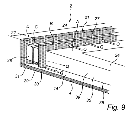
guide rail. With reference to Fig. 9, the drainage channel 29 extends from the
CA 02712350 2010-07-15
WO 2009/093957 PCT/SE2009/000023
13
gap 28, transversely of the contact surface 30 between the second sealing
strip 27 and the bottom surface 31 of the inner longitudinal surface 14 of the
guide rail 4 and further out into the guide rail towards the lower, first
trans-
verse edge portion 42 of the panel. As seen in the longitudinal direction of
the
guide rail, see Fig. 7, the drainage channel 29 is defined by the fourth
sealing
strip 33 (described below), the bottom surface 31 of the inner longitudinal
surface 14 of the guide rail 4 and the web 6 of the U-shaped guide rail. In
the
case of roofs, the fact that the suspension profile is mounted at an angle to
a
horizontal plane means that draining of moisture occurs naturally.
The drainage channel 29 may be created by incomplete filling up of the
space between the underside 36 of the panel and the bottom surface 31 of
the guide rail, as shown in Figs 7 and 9, or by the sealing strip 27 having a
lower degree of compression along the bottom surface 31 of the guide rail 4.
In the first case, an unobstructed drainage channel 29 is formed. In the
second case, the moisture is able to escape through the structure of the
sealing strip, i.e. through its bristles, fibres or porosity. The function of
the
drainage channel will be described in more detail below.
The first 22 and second 23 sections, respectively, of the second
sealing strip 27 may help to form a sliding surface 26 against the guide rail,
although this is not their main purpose.
Referring yet again to Figs 3a-3c and to Figs 6a-6c, the gap 28 formed
between the first 21 and the second 27 sealing strip will thus extend along
the
upper side 34 of the panel 2, further down around the longitudinal, vertical
side edges 35 and down along the underside 36 of the panel.
The bottom surface of the gap may either be flush with the surface
formed by the frame of the panel or be a recessed groove. The bottom
surface 37 of the recessed groove is illustrated schematically in Fig. 3a in
the
form of a broken line.
With reference to respectively Figs 3a and 3b and Figs 6a and 6b, the
panel 2 further comprises third sealing strips 32 on its upper side 34 and,
more specifically, along its two longitudinal edge portions 39. Said third
sealing strips 32 extend from the second transverse edge portion 38 of the
panel to its first transverse edge portion 42 and are in contact, in the
second
transverse edge portion, with the second sealing strip 27 for forming a
continuous joint with the same.
With reference to Figs 3a and 3c and Figs 6a and 6c, the panel 2
further comprises fourth sealing strips 33 on its upper side 36 and, more
CA 02712350 2010-07-15
WO 2009/093957 PCT/SE2009/000023
14
specifically, along its two longitudinal edge portions 39. Said fourth sealing
strips 33 extend from the second transverse edge portion 38 to the first
transverse edge portion 42. Depending on the extent to which the first 22 and
second 23 sections of the second sealing strip 27 enclose the longitudinal
edge portions 39, the fourth sealing strip 33 may be in contact with both the
first 21 and the second 27 sealing strip for forming a continuous joint
therewith (Fig. 3c), or only with the first sealing strip for forming a
continuous
joint with the same (Fig. 6c).
The purpose of the third 32 and fourth 33 sealing strips is to form a
fluid tight seal against the lower 10 and upper 9 surfaces of the inner
longitudinal surface 14 of the guide rail 4, see Fig. 8. By this is meant a
sealing effect between the third and the fourth sealing strip, respectively,
and
their contact surfaces in the guide rail such that air and moisture, with
dimensioning parameters for normal wind loads, are unable to penetrate. The
sealing strips may be made of a diffusion tight material. Examples of this
type
of material are a heavily compressed brush-type seal, a brush-type seal
comprising a film which extends in the direction of the bristles or an
extruded,
flexible strip of, for instance, rubber, plastic or silicone. It will be
appreciated
that the sealing capacity is dependent not only on the choice of material but
also on parameters such as the degree of compression and the width of the
sealing strips. It is obvious to the person skilled in the art to identify a
sealing
strip that is suitable for this purpose.
With reference to Fig. 4, it is illustrated that the first 21 and second 27
sealing strips may be arranged in grooves 40 running in the second trans-
verse edge portion 38. The grooves, which may be omitted, serve two pur-
poses. First they provide what can be described as a pre-forming of the
profile of the sealing strips, since the wall portions 41 of said grooves will
limit
the lateral extent of the sealing strips when they abut against the surface
against which they are intended to seal. This provides a better sealing
effect.
Second, the grooves also help to prevent the sealing strips, which are
typically attached by gluing, from becoming slightly offset due to the shear
force to which they are subjected as the panel is moved along the guide rail
for the purpose of opening/closing.
With reference to Fig. 4, the panels 2, 2a are, in their mounted state,
movably inserted in the guide rails of the suspension profile in an
overlapping
manner. When the two panels forming a pair have been moved to their closed
position, the first transverse edge portion 42 of the upper panel 2a will
overlap
CA 02712350 2010-07-15
WO 2009/093957 PCT/SE2009/000023
the second transverse edge portion 38 of the lower panel 2. The overlap
occurs in such a manner that the third sections 24 of the first 21 and the
second 27 sealing strip, respectively, of the lower panel 2 will abut and seal
against the underside of the first transverse edge portion 42 of the upper
5 panel 2a. The overlapping panels define between them an air pocket 43,
which is open towards the first transverse edge portion 42 of the upper panel
2a.
In the following the function of an openable roof or openable wall
according to the embodiment described above will be described with
10 reference to Figs 9 and 10.
The openable roof/wall according to the invention can be said to have
four sealing zones A, B, C and D, which all serve as an obstacle to an
incoming flow of air Q and airborne moisture, but also as a protection against
penetration of dirt. The first zone A consists of the air pocket 43 that is
formed
15 between each pair of overlapping panels 2, 2a. The penetrating air Q must
initially have sufficient kinetic energy to be able to penetrate into this air
pocket 43, thereby reaching the second sealing strip 27, which forms a
second zone B. Once there, the air still needs enough kinetic energy to
enable it to penetrate through the second sealing strip 27. On its way through
the second sealing strip 27, large particles such as dust, pollen and sand are
filtered out. The filtering effect is due partly to the density and structure
of the
second sealing strip 27, partly to its seal against the upper panel 2a. The
air,
moisture and dirt that, despite the above obstacles, are able to penetrate
through the second sealing strip 27 will enter a third zone C, which consists
of
the gap 28 between the first 21 and the second 27 sealing strip. In the third
zone C more kinetic energy is lost due to the sudden increase in volume to
which the air Q is subjected in the gap 28. By now the air Q has lost so much
kinetic energy that it is simply not capable of penetrating through the fourth
zone D, which consists of the first sealing strip 21. Instead the air Q will
spread in the gap 28. And so will the moisture, no matter whether it is in
liquid
form or vapour form.
By the first 22 and second 23 sections of the first 21 and second
sealing strips 27 at least partially enclosing the longitudinal edge portions
39
of the panel, the gap 28 will have the same extension as these two sealing
strips. The gap 28 thus extends from the upper side 34 of the panel 2, around
the longitudinal edge portions 39 and further down onto the underside 36 of
the panel. As a result, the air Q and, in particular, the moisture will travel
CA 02712350 2010-07-15
WO 2009/093957 PCT/SE2009/000023
16
through the gap 28 and down towards the underside 36 of the panel and,
more specifically, onto the bottom surface 31 that is formed on the inner
longitudinal surface 14 of the guide rail 4. Moisture in liquid form, if any,
will
be able to flow along the guide rail in the drainage channel 29 formed
between said bottom surface and the underside of the first and the second
section, respectively, of the second sealing strip 27. Moisture in vapour
form,
if any, will be able to either escape through the drainage channel or pass by
way of diffusion through the structure of the second sealing strip and further
out through the drainage channel along the guide rail, all depending on the
abutment of the second sealing strip against the bottom of the guide rail.
In view of the above, it will be appreciated that it takes extreme wind
loads to overcome the sealing effect of the first and second sealing strips,
thereby enabling air, moisture and dirt to penetrate between the panels and
into their guide rails. The air and moisture that do after all penetrate is
allowed
to escape, in a controlled manner, through the gap and the drainage channel.
Dirt in particulate form is filtered out very efficiently by having it pass
through two zones, on one hand the air gap between two overlapping panels
and on the other the second sealing strip, before it is able to penetrate into
inaccessible spaces between the panels and the inside of the guide rails.
Since a roof, in normal use, is mounted at a certain angle to a hori-
zontal plane, the suspension profiles with their guide rails will be mounted
at
the same angle. This means that any moisture/dirt that penetrates into the
guide rails will be conveyed downwards through the drainage channel.
Drainage does not occur through gravitation only, but also through the
scraping motion occurring between the guide rails and the first and second
sections, respectively, of the first and second sealing strips as the panel is
displaced relative to the guide rail for the purpose of opening or closing.
The above concept is applicable in the same way as for an openable
wall with mutually displaceable panels, which in normal use are arranged
substantially vertically.
It will be appreciated that in an openable wall according to the present
invention any moisture that penetrates into the gap between the first and the
second sealing strip will drain off downwards due to gravitation in the
direction
of the drainage channel formed between the lower longitudinal edge portion
and the lowermost guide rail. However, moisture in vapour form will be able to
travel upwards along the gap and escape through the drainage channel
CA 02712350 2010-07-15
WO 2009/093957 PCT/SE2009/000023
17
formed between the upper longitudinal edge portion and the uppermost guide
rail.
It will be appreciated that the present invention is not limited to the
embodiments described above. Several modifications and variants are
conceivable and, therefore, the scope of the present invention is defined
solely by the appended claims.