Note: Descriptions are shown in the official language in which they were submitted.
CA 02712746 2014-03-27
ONLINE MEASUREMENT SYSTEM OF RADIOACTIVE TRACERS ON OIL
WELLS HEAD
DESCRIPTION
TECHNICAL FIELD OF THE INVENTION
The present invention is concerned with a system for tracers detection which
emits
gamma radiation at the head of production wells, in order to monitor in real-
time
concentration values of tracer activity, and that it will be able to operate
autonomously according to a monitoring established program, and in this manner
to be able to collect more data, which contributes to reduce the uncertainty
level
and to increase analysis efficiency and interpretation of the results of
tracer tests.
BACKGROUND OF THE INVENTION
The main goal during the exploitation phase of an oil reservoir, from a
technical-
economic point of view, is to obtain the optimal hydrocarbons recovery, so
that it
remains the least amount of residual oil in the reservoir. In order to
increase the
amount of oil, it is used the secondary and/or enhanced recovery processes,
which
mainly consist in injecting fluid for providing additional energy to the
reservoir,
taking advantage of this energy in the displacement of hydrocarbons towards
production wells.
The tracer tests among wells are a widely used tool in the recovery processes,
in
order to determine the flow trajectories of injection fluids, as well as to
detect high
permeability zones or drainages that cause a disproportionate distribution of
injected fluids, which can be reflected on an efficiency process reduction.
In documents found in tracer tests literature, the sampling test is performed
through a visit to the field of selected production wells, by trained
technical staff;
1
CA 02712746 2014-03-27
this task is carried out according to a previously established sampling test
program
during the design stage of the activities for the tracers injection to the
reservoir.
This program usually takes into account a high sampling test frequency the
days
immediately after the tracer injection, so that going down its frequency as
long as
the time passes through. The reason of high frequency at the beginning is the
possibility of the presence of tracer due to drainage which breakthrough the
tracer
in the production well very quickly. This matter produces a very short tracer
response but at the same time of great magnitude so that it can be only
possible to
reconstituted if it is possible to have a sufficient number of sampling tests.
Otherwise, when there is not drainages, the tracer flow more slowly in the
porous
media, so the scheduling of sampling tests collection is at least one year,
and then
to accomplish that the tracer response more closely reflect what happens in
the
reservoir. Taking into account the above description, the cost of the sampling
test
of a tracers test rises sharply, due to the large amount of sampling tests. It
is worth
to say that a substantive part of the cost of a tracer project corresponds to
the
analysis of sampling tests, and often it is sacrificed the number of sampling
tests in
order to reduce the project costs. However, the information obtained from
tracer
tests is directly proportional to the number of analyzed sampling tests.
One of the main problems that arise when interpreting a tracers test results,
and
even, reaching some failure cases, is caused by a poor and/or insufficient
monitoring program. This may be due to several factors, mainly to an
inadequate
program design of the sampling test, or it could also be due to other causes,
such
as, difficulty of moving through long distances for carrying out the sampling
tests,
impossibility to perform the sampling tests due to affectations caused by
farmers
who did not allow access to the wells, remote offshore platforms, or it could
also be
due to the lack of available resources (human, economics) for sampling tests:
The main advantage that represents the radioactive tracers is the possibility
of
working with small volumes for its injection and in many cases, especially for
gamma emitters, its facility for being detected in-situ. However, the
radiation
2
CA 02712746 2014-03-27
measurements for radioactive isotopes of low energy beta emitters such as
tritium
(18 keV maximum beta energy) and carbon-14 (155 KeV) are not carried out in
the
field, because their analysis is carried out with special low level count
equipment,
therefore all samples are sent for their analysis to specialized laboratories
that
have liquid scintillation counters equipments. In another case, the use of
radioactive isotope tracers that emit gamma radiation, such as: 57Co, 58Co,
80Co,
1921r or 1311, they make much easier their detection, which can be achieved
through
scintillation crystals. The sodium iodide detectors activated with thallium,
Nal(TI),
are widely used for the detection of gamma radiation, which given its
characteristics make possible that they can be used in the field, which allows
it
become unnecessary to perform a sampling test and then to send it to the
laboratory for radio-chemical analysis.
Currently, for measuring gamma radiation, there are a several commercial
laptops,
however, its use is focused on general applications, and among these kind of
commercial mobile computers it can be mentioned the following models: 1000
Inspector, Inspector 2000 Canberra brand, and others from the Ortec brand.
It is important to mention that if commercial equipment are intended to be
used for
detecting radioactive tracers in a intrusive way, which is known by the term
of "on-
line detection," in the head of production wells, these equipments would
present
serious disadvantages in compared with the system developed in this invention,
such as:
1. Non-intrusive measuring drill. They cannot directly measure the radiation
contained in fluid from of the reservoir.
2. They are portable, but with battery life which last from 3 to 10 hrs. Which
does
not allow us to connect them to the wells permanently.
3. They do not have data storage capacity for testing lasting long periods of
time
(months).
4. Temperature operation is very limited (maximum 55 C).
3
CA 02712746 2014-03-27
,
5. They do not operate on an autonomous manner, i.e. they require the
permanent
presence of an operator.
It is worth to say that it has been reported (Tracers In The Oil Field, Zemel
B., The
Netherlands, 1995, Elsevier Science B.V.) applications in tracer tests, where
it is
mentioned that radioactive tracers measurements can be performed in-situ by
using detectors Nal(TI), however, features of the measurement system are not
specified and even less if they are commercially available equipment, or
having
similar characteristics to the system of the present invention.
There are also commercial tools or systems as Spectral Gamma Ray Tool,
TracerScanTm, etc., from different companies like Halliburton, Schlumberger,
International Protechnics, among other companies, whose application is the
natural
gamma radiation log test, or also gamma spectroscopy applications, within oil
wells,
these tools are used to characterize the stratums, and they operate at
conditions of
high temperature and pressure. However, these tools are designed to operate
inside the wells, so they do not meet all the features and operating purposes
of the
measurement system that is result of this invention.
Likewise, with regarding to the above they are published large number of
patents
relating to tools and systems to make profiles of gamma radiation inside the
wells,
focusing to different applications. For example, in US Patent 4007366, relate
equally to systems and apparatus for take a radiation intensity profile of
tracer in
different runs that are performed inside the wells. The arrangements consists
of a
background tool (drill), which has two types of radiation detectors Geiger
Muller, a
device for injecting a tracer charge inside the well, a telemetry module to
transmit
data between the drill and the surface equipment. The pulses generated by
detectors, are sent to the surface equipment through a cable record. The unit
on
the surface, has all the postcards for the management of the pulses from the
background tool, electronic arrangements for corrections of the readings,
discrimination circuits, counters, power supplies to provide the energy needed
to
4
CA 02712746 2014-03-27
_
power electronic circuits in the equipment fund, etc. Given the
characteristics of the
detectors used, this system cannot differentiate between two or more tracers
used,
nor can operate autonomously.
Other patents mentioned techniques developed for specific applications related
tools also for operate in the interior of the wells, such is the case of US
Patent
4481597, which refers to an analog to digital converter or spectrum analyzer
for
use in a drill for making logs of spectrum gamma ray within the wells. The
system
converts analogic pulses generated by the photomultiplier tube in a digital
representation or digital word. This digital representation has the form of
numbers
representing the energy of gamma rays or other types of nuclear radiation that
produces scintillations in the crystal detector, which is optimally coupled to
the
photomultiplier tube. The digitized value is transmitted by the drill to the
surface
through cable record.
Also there are published other developments related to the sampling of fluids
in
wells, as mentioned in the reference US Patent 4454772, which describes a new
method for automated fluid sampling wells. This method is basically of a
series of
solenoid valves to inject fluid from the well to a number of sample containers
are
filled one after another, through the valves that are electrically driven by a
programmable switch. Later, with the series of containers collected samples
are
sent for laboratory analysis. The novelty of the method of the present
invention is
to automate the sampling of fluid from the wells, thus avoiding moving staff
to the
sampling points.
The references mentioned above were created for entirely different
applications of
the present invention, by virtue of this we have implemented an online
measurement system of radioactive tracers in the wellhead in an offshore
producer
of oil, which allows continuously monitor the presence or not presence of
three
different tracers, above to determine with greater precision the times of
arrival of
CA 02712746 2014-03-27
_
the tracer, while eliminating the need to allocate staff to carry out sampling
operations, with all advantages that this represents.
Therefore, one of the objects and advantages of the present invention is to
provide
a measurement system that allows online monitoring and permanent values of
tracer concentration, and is able to operate autonomously according to a
program
monitoring previously established based on the design and objectives of the
injection of tracer to the site, and thus have more data from the tracer
activity,
which reproduce the response curves of tracer, which contribute to reduce the
level
of uncertainty and increase efficiency in the analysis and interpretation of
results.
BRIEF DESCRIPTION OF THE DRAWINGS OF THE INVENTION
It provide the following FIGS. 1, 2 and 3, in order to understand clearly the
online
measurement system of radioactive tracer activity in oil fields, and serve as
a
reference in the application example provided in the following paragraphs.
Although the figures illustrate specific provisions of equipment, with which
are can
go to the practice the present invention, should not be understood as limited
to a
specific computer.
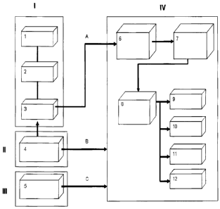
FIG. 1 illustrates a block diagram which shows the parts that make up the
online
measurement of activity of radioactive tracer in the head in production wells
of oil
fields, cause for complaint as an innovative system.
FIG. 2 shows a schematic diagram of the measurement system on-line radioactive
tracer, installed between the tubing (before the choke) and Oil Pipe Line
(after the
choke) in a well in production, at an oil reservoir.
FIG. 3 shows a schematic representation in a greater detail of the measurement
system and arrangement of connections required for operation through a bypass
flow between the production pipeline and the Oil Pipe Line.
6
CA 02712746 2014-03-27
DETAILED DESCRIPTION OF THE INVENTION
This system object of the present invention was developed with the aim of
satisfying the requirements of detection and measurement of the arrival of
radioactive tracers that emit gamma radiation, in the head of production wells
of oil
fields.
In accordance with FIG. 1, the system basically consists of four parts:
l. The radiation detector.
II. The power plant.
III. Laptop.
IV. Data Acquisition Equipment.
The following describes each of the different blocks and their interrelation.
I. Radiation Detector (blocks 1 to 3 of FIG. 1).--This device, as shown in
FIG. 1,
consists of three elements: the scintillation crystal made of Nal (TI) and
photomultiplier tube (block 2) the high-voltage source (block 1) and an
amplifier
(block 3). The radiation emitted by the fluid tracer from the field, which
flows
through the container type Marinelli, strike the scintillation crystal,
producing
flashes to be connected to the photomultiplier tube, is generated out of this
a
proportional electrical signals the energy of the incident radiation, these
pulses
generated finally enter the stage of signal amplification. A brief description
of each
of the three components of the radiation detector is explained next:
1) High voltage source (block 1 in FIG. 1).--This is a switching power supply
delivering between 1200 and 1500 Volts needed to polarize the photomultiplier
tube through a resistive-capacitive arrangement. This source of high-voltage
bias
required for a direct-current power supply +/-15 Volts, which is provided by a
converter AC/DC powered in turn by the solar plant (converters AC/DC).
7
CA 02712746 2014-03-27
_
2) Scintillation crystal and photomultiplier tube (block 2 in FIG. 1).--It is
the primary
element radiation detector. It is sodium iodide activated with thallium Nal
(TI).
Cylindrical geometry has a diameter of 2 inches and 4 inches long. This type
of
detector was selected considering the ability to distinguish different
energies of
radiation, which allows us to differentiate the arrival of several tracers
simultaneously. The function of the scintillation crystal is to make the
conversion of
gamma radiation incident visible electromagnetic energy. The scintillation
crystal is
coupled to a photomultiplier tube (PMT), whose function is to convert the
electromagnetic energy in the visible region that delivers the scintillation
crystal, in
pulses of electrical energy. Model was selected photomultiplier used to
achieve the
coupling of the whole energy range of incident gamma radiation, measurement of
50-2000 keV.
3) Amplifier (block 3 in FIG. 1).--By this module, the pulses are amplified
signal
from the photomultiplier (PMT). This module is also powered with +/-15 Volts
CD.
Features and specifications of the radiation detector, Model: 2GR4/2L-XM,
Brand:
Saint-Gobain Crystals:
Dimensions complete radiation detector: 2.37 x 15.59 inches.
Detector comprising a scintillation crystal, photomultiplier tube, high
voltage source
and signal amplifier.
Scintillation crystal dimensions: 2x 4 inches (diameter, length).
Radiation to be measured: Gamma.
Detection range: 50-2000 keV.
Operating Temperature: 150 C.
Pulse Height Resolution: 7.5% Cs-137.
Material from the cover: Stainless steel.
8
CA 02712746 2014-03-27
It is important to mention that the radiation detector was specially designed
and
built by Saint-Gobain Crystals, according to design specifications and
parameters
provided by the Tracer Technology Area of the Institut Mexicano del Petroleo
(IMP).
Container radiation detector (represented by number 5 in FIG. 2).--
To increase the efficiency of detection module, we designed a Marinelli
container
type, stainless steel with an effective volume of 2.3 liters of fluid to
reduce
undesirable background radiation from the environment, covered container with
lead shielding 1/2 in thick, which allows increasing the minimum level of
detection.
The container detection module was designed and built to withstand a maximum
pressure of 1,600 psi, which is invention is not limited to operate at
pressures
above this value. This container was designed only for the radiation of Saint-
Gobain Crystal, which is described here.
II. Power plant (block 4 in FIG. 1). This module is only one component,
described
below.
4) Power source of the entire system, consisting of a photovoltaic panel, a
bank of
two batteries, a controller and an inverter DC/AC. With this inverter are
generated
at 60 Hz 127 volts to power converters, AC/DC Voltage with outputs of +/-15 V,
+12 V and +5 V direct current necessary to energize both the radiation
detector as
other electronic circuitry in the data acquisition module.
The elements that make the solar plant, were selected to allow electric energy
supply to the measuring system, up to 72 hours on days of total darkness. The
power supply is permanent on a sunny day or a little sun. Other
characteristics of
the elements that make up this block are:
Monocrystalline photovoltaic module, is 75 Watts.
PV controller 2 Batteries 100 Amp/hr.
9
CA 02712746 2014-03-27
Investor of current.
Converter AC/DC +/-15 Volts and 0.50 Amps output.
Converter AC/DC +5 Volts and 3 Amps output.
III. Laptop (block 5 of FIG. 1). This module has only one component, described
below.
5) For programming and retrieval of data acquired during or at the end of the
field
test carried out. Communication between the device and measuring system, is
effected by the protocol via RS-232 serial port at 9600 baud. Similarly, the
data
processing is performed on this computer. To this end, it was a program in
Visual
Basic within Excel tool for Microsoft Office.
Through line A in FIG. 1, is performed signal coupling between the power
amplifier
radiation detector and the entrance to the stage of signal conditioning in
data
acquisition. Through the communication represented by line B in the figure,
power
is provided throughout the system, and reading of data stored in the system is
done via a laptop computer through a communication port RS-232 (represented by
line C of FIG. 1).
IV.--Data Acquisition Equipment (block 6 to 12 in FIG. 1).--Using this
equipment,
process the pulses from the detection module, has the electronic circuits:
signal
coupling through a simple differentiating circuit, discrimination pulses with
voltage
thresholds and timing, a monostable multivibrator and a signal conditioning
stage,
later entering the counter circuit based on a preset time window, then the
data is
stored in memory according to the monitoring program established. The
information is continuously displayed on a display numbers and as additional
support, the information displayed on screen prints.
CA 02712746 2014-03-27
Here are the main functions of each of the stages that compose the
programmable
data acquisition equipment and the relation among them, corresponding to
blocks
6 to 12, according to FIG. 1:
6) Phase comparison and signal conditioning (block 6 of FIG. 1).--This stage
consists of three channels of comparison, earlier in order to be able to
detect up to
three different radioactive tracer. Each of the comparators is set to an
adjustable
reference voltage, which corresponds to a detection threshold of the energy of
the
radiation emitted by the tracer detection is required. Following this section
is a
monostable multivibrator designed to standardize the width of the pulses to
0.8 us.
The purpose of the above, is to avoid problems of overlapping pulses,
resulting in
erroneous reading would count them. As a protection against noise, which
similarly
could cause false triggering, the output signal of the previous stage, is
coupled
through an RC circuit and a gate array to the next stage: the counting of
pulses.
7) Step counting of pulses (block 7 of FIG. 1).--As the name implies, this
stage is
done counting the pulses from the phase comparison and signal conditioning.
This
has an adjustable time base, allowing count pulses at a frequency of 3.66 msec
each to each 8:32 pm. The measuring window was prefixed in 1 minute may count
up to 224 pulses, that is 16.78 x10⁶ pulses per minute to the time window
selected.
8) 16-bit microcontroller (block 8 of FIG. 1).--The integrated microcontroller
is used
in a development board. Through this device, it performs the function of
programming and control, data read from the stage of counting and writing them
in
memory, as well as the results displayed on screen and printing of the thermal
paper. The electronic card microcontroller with a bank of read-only memory
(RAM)
256 Kbytes, which added to 256 KBytes of internal flash memory that holds the
microcontroller, provides a total of 512 Kbytes of user memory. Another
feature of
the microcontroller, it has ports for 12 C and SPI communication. The latter
allow
you to link serial devices such as memory, allowing larger data storage
capacity of
the system, if they require the application.
11
CA 02712746 2014-03-27
We developed a software in C language, which was compiled, by which the
microcontroller performs all control tasks of acquisition, storage and
information
management.
9) Output interface for the user.--Communication between the user and the
microcontroller is done through a keyboard (block 9 of FIG. 1), by which all
values
are entered the required parameters for programming measurement (frequency
counting). As a means of display, it has a liquid crystal display, LCD, and
has a
thermal printer, as a means of additional support for the information.
The alphanumeric keyboard is 4 columns x 4 rows. The display or LCD screen is
4
rows and 16 alphanumeric characters per line. The keyboard is connected to the
microcontroller through port H of the microcontroller. This port is configured
as
input or output (I/0) and LCD display communicates via SPI port.
10) Printer (block 10 of FIG. 1).--As mentioned earlier, to have additional
support
from the acquired data, joined to the measuring system, a thermal paper
printer.
Communication between the microcontroller and the thermal printer is done via
the
serial port at a speed of 9600 baud.
11) Report of data (block 11 of FIG. 1).--This consists of a bank of read-only
memory (RAM) 256 Kbytes, which added to 256 KBytes of internal flash memory
that holds the microcontroller, gives a total 512 Kbytes of user memory. The
programming is done in the same way paged.
12) The keyboard (block 12 of FIG. 1) is alphanumeric.--4 columns x 4 rows.
The
keyboard is connected to the microcontroller through port "H" of the
microcontroller.
This port is configured as input or output (I/0).
12
CA 02712746 2014-03-27
Finally, it is noteworthy that the electronic equipment buyer, is contained
within a
special case made of aluminum according with the NEMA code type 4 (NEMA is
National Electrical Manufacturers Associations, type 4 refers to a case
constructed
for either indoor or outdoor use, to provide a degree of protection to
personnel
against access to hazardous parts) that protects it from adverse environmental
conditions. We should also mention that this computer is powered by
alternating
current (AC) of 127 Volts and 60 Hz, from the solar plant. This alternating
current is
converted to direct current of +/-12 Volts and 5 Volts, needed to operate the
electronic circuitry above and to polarize the radiation detector. To move
from this
alternating current to direct current converters used the following AC/DC:
Lambda Converter KWD10-1212 model of +/-12 Volts and 0.45 Amps output.
Converter KWS15 model Lambda-5 +5 Volts and 3 Amps output.
Finally, it is noteworthy that the electronic acquisition equipment, is
contained
within a case according with the NEMA code type 4, which protects it from
harsh
environmental conditions which must operate. We should also mention that this
computer is powered by alternating current (AC) of 127 Volts and 60 Hz, from
the
solar plant. This alternating current is converted to direct current of +/-15
V, +12 V,
needed to operate the electronic circuits mentioned above, as well as
providing
energy to the detection module. To move from this alternating current to
direct
current used the following sources of DC power (converters AC/DC) of +/-15
Volts
and 0.5 Amps output to +5 Volts, 3 Amps output.
Description of the procedure used for installation and operation measurement
system radioactive tracers online at the head of production wells. FIG. 2 and
FIG. 3
(Detail A), shows the elements needed to install the equipment on the premises
of
the production wells in the field under study.
As shown in Detail "A", FIG. 3, the data acquisition system (8), container (5)
together with the sensor (12), the battery module (9) and the solar cell (7)
are
installed on a pipe or pole (23). The container is arranged for coupling
mechanical
13
CA 02712746 2014-03-27
=
connections and stainless steel tubing or reinforced hose for fluid entry and
exit of
the container, both the tubing and in which case the hose must withstand the
operating pressure and temperature of the well, in one of the wells in which
validated the computer, the operating pressure at the well head was 900 psi
and
the temperature in the head of 119 C. FIG. 2 shows the connection lines (21
and
22), one of them taking well fluid (21), connects before the choke (2), and is
fed to
the container (5) Valve (4) regulates the flow into the container. The output
of the
fluid is made by connecting the line (22) to the Oil Pipe Line (3) is tied
with the
head of the oil collection leading to the separation station. The connection
of the
line (22) must be made to a valve (10) whether or regulatory step. Normally
the
valves (4) and (10) are part of an array of valves, that are installed on the
operating
lines of the well and is used for oil sampling and measuring the pressure
through
mammography manometers installed that monitor operating conditions of both the
wellhead and the Oil Pipe Line. In the event that these valves do not exist in
this
way, you need to install to ensure proper system operation. The container must
have installed a valve (11) and a hose for venting and depressurization of the
system.
In the implementation phase, first of all must make sure that the solar cell
(7), the
data acquisition system (8) and all electrical components, are operating
properly.
You should also ensure that the data acquisition program is scheduled properly
considering the duration of the operation. To ensure that the fluid flow on
the
system of tubing and container must be a difference in pressure between the
pressure and the pressure of the Oil Pipe Line. Obviously the pressure at the
wellhead must be greater than the pressure of the Oil Pipe Line, on the
operational
phase it must kept this difference of pressures.
Once installed to the computer as shown in the diagram in FIG. 2, opens the
valve
(4) to regulate the proper flow, vented in the first instance by the valve
(11), having
confirmed the flow, closes the valve (11) and opens the valve (10), which the
oil is
14
CA 02712746 2014-03-27
a
flowed into the system. You should keep a manual record of the variation of
pressure from the wellhead and the Oil Pipe Line and if possible the
container.
According to FIG. 2, the output interface for the user (Display),
communication
between the user and the microcontroller is done through a keyboard (16), in
which
all values are entered the required parameters for the programming of the
measurement (frequency count). As a means of display, it has a liquid crystal
display, LCD (15), and a thermal printer (17) as a means of additional support
information.
As mentioned previously, to have additional support from the acquired data was
integrated to the system of measurement, thermal paper printer (17).
Communication between the microcontroller and the thermal printer is done via
the
serial port at a speed of 9600 baud.
Finally, it is noteworthy that the electronic acquisition equipment is
contained within
a case NEMA type 4 (8), which protects it from harsh environmental conditions
which must operate. We should also mention that this computer is powered by
alternating current (AC) of 127 Volts and 60 Hz, from the solar plant.
EXAMPLE
The following example is presented to illustrate the operation of the online
measurement system of radioactive tracers in oil well head. This example
should
not be considered as limiting the claims here, but simply describes the
procedure
whereby operation tests were performed measuring system online source of this
invention, in one of the tests conducted in oil production wells.
We describe useful framework and requirements to which the computer responds
developed, and also, a brief description of the measurement system and its
main
CA 02712746 2014-03-27
components, the wiring diagram required for testing for the equipment.
Referring to
FIGS. 2 and 3, have the following:
Description of specialized valves of valves used:
1.) Needle valve 1/2"-NPT (4) to control the container flow
2.) Needle valve 1/2"--NPT (10), Security outflow towards the Oil Pipe Line.
3.) Ball valve 1/2"-NPT (11th) for phase lock control flow.
4.) Needle valve 1/2"-NPT (11), to purge and depressurization of the system.
Description of operations needed to establish the flow measurement device line
tracers: Once installed the system as shown in FIG. 2 and as specified above,
the
system must be connected before the choke, the will be making fluid and the
fluid
outlet must be connected to a choke point after on the same line where you
have a
pressure difference, it is the Oil Pipe Line that reaches the head of
collection. Then,
it performs the following procedure to enable the operation of the system for
online
detection of tracers.
FIG. 3 shows the components of the detection system used for the development
of
operations in the procedure.
Operation 1.--Establishment of Flow
Step 1.--Check that all valves 4, 10, 11a, 11 are fully closed.
Step 2.--Check that hose is placed a valve 11 to a storage container vent
fluids.
Step 3.--Verify is an instrument for measuring pressure at points of
connection, this
may be gauge or chart recorder pressure called "manografo", in which case you
need to install this device.
Step 5.--Manipulating the valve 4, gradually opening it up to a quarter turn
around,
just as you open the valve 11 regulating the flow slowly to 1/4 turn. The
valve 11a
and valve 10 remain closed, maintaining the flow for a term May to 15 seconds,
16
CA 02712746 2014-03-27
checking the level of container harvesting should be noted that this container
will
only be used at this stage and in full operation should not be present.
Step 6.--Valve 11 is closed and fully open the valve 11a, the valves remain
closed
10, which is the conjunction with the Oil Pipe Line of the well. In this step
it is
suggested to maintain a pressure monitoring system throughout the entire
process.
In the same manner, it is recommended to verify the existence of unions and
fix
leaks in such case before making the oil flow on the system.
Step 7.--Gradually opened fully the valve 10, permitting the flow connection
to the
flow system of the Oil Pipe Line. Establishing the flow and pressure is
monitored
over a period of time.
Operation 2. Flow Regulation on the Line Feeding the Container
Once flow is established and verified that no leak in the connections
necessary to
regulate the flow to ensure the movement of fluid in the line and the
container.
Step 1.--Check that hose is installed in the valve 11 and it is within the
container for
collecting fluids from the well.
Step 2.--Check that the valve 11 is closed.
Step 3.--Fully close the valve 11a.
Step 4.--Close the valve 4 and then open it slowly to regulate the flow line
from the
container to the desired flow, making flow measurements over time.
Step 5.--Open slowly until all the valve 11.
Step 6.--Check the volume of container that stores the vent fluid, taking care
not to
spill.
Step 7.--Verify at any time pressures on the gauges. In this operation, as a
first test,
the flow was regulated at a cost of 1 liter in 25 seconds; it is noteworthy
that output
regulation is done at atmospheric pressure where the pressure difference is
very
high, making the oil flow on the new line of low pressure difference by
reducing
fluid volume. Once adjusted the flow proceeds to perform the following steps.
Step 8.--Close valve 11.
Step 9.--Check gauge pressure at the head and the Oil Pipe Line.
17
CA 02712746 2014-03-27
_
-
Step 10.--Open slowly and in full the valve 11a, to establish the flow.
Step 11.--Check the setting on the system flow is necessary to consider the
motion
of fluid in all items of equipment.
Once adjusted, the flow goes to work the system and monitor the pressure data.
Table 1 shows an example of data taken in a well where test runs were
conducted.
Moreover, it is important to note that the data acquisition system must be
programmed to acquire data for as long as the rest of the procedure, and only
need to verify that the power supply to work properly, since it depends on
energy
solar. At this stage of operation, the acquisition system records the energy
intensity
of the radioactive tracer that is used and is blended in the aqueous phase in
the
production of hydrocarbon reservoir.
Table 1. Pressure data with a regulated flow It/25 seconds
Pressure Pressure Oil
Pressure on
gauge 2 Pipe Line
Time the wellhead
(Container) connection
Psi
Psi Psi
13:50 890 440 430
13:55 890 440 430
14:00 890 435 430
17:46 890 420 430
17:50 890 450 430
Operation 3. Depressurization and Purging of the Measuring Equipment
After completing the operations for the detection and measurement of tracer in
line
at the wellhead, we proceed to disconnect the computer by using the following
procedure:
18
CA 02712746 2014-03-27
_
Purge and Depressurization of the System
Step 1.--Check that the valves 4, 10, 11a are operating efficiently, the valve
11
must be closed.
Step 2.--Check that the valve 11 hose is placed to a storage container vent
fluids.
Step 3.--Manipulating the valve 4, closing gradually until full.
Step 4.--Manipulating the valve 10, closing gradually until full.
Step 5.--Check that the pressure of the wellhead and the Oil Pile Line was
reintroduced in its original condition.
Step 6.--11th valve is closed and fully open the valve 11, the remaining fluid
should
go into the collection container, avoiding spills on the floor. This step is
depressurized the line between the wellhead and the container.
Step 7.--Slowly opens in full the valve 11a, now allowing the container and
the line
that goes to the Oil Pipe Line lose pressure.
Step 8.--Verify that the remaining fluid was being removed from the entire
system.
Step 9.--Check again that the valves 4 and 10 are closed.
Step 10.--Proceed to disconnect from the production facilities if necessary.
Comments
As part of the results of tests conducted in a well in production, you can
mention
the following:
= The system operates satisfactorily to the conditions of temperature and
pressure
of 880 psi and 115 C, respectively. It is noted that these conditions are
high.
Similarly the system is expected to work well under pressure conditions and
temperature. Therefore, one can say that the system was tested under extreme
conditions.
= The system was operating and recording data for a total 53 hours, of
which, 15
hrs operated without fluid flow flowing through the container, and 38 hrs from
spending registered site.
19
CA 02712746 2014-03-27
_
=
= The different conditions for the tests, without fluids, namely, operating
at room
temperature, at different costs, allowed to observe and evaluate performance
at
different operating temperatures.
Conclusions:
= A summary of some points of tests the equipment: It was possible to
measure
the radioactivity (gamma emission) contained in the fluid from the reservoir,
connecting such a system between the production tubing Oil Pipe Line and
production, i.e., measuring the flow production line and in real time, with a
window
measuring 1 minus.
= The system works perfectly with the operating conditions of the well, the
pressure in one case was approximately 900 psi and 450 psi the Oil Pipe Line.
Maximum working pressure is by design: 1,600 psi.
= The system works fine with the production fluid to a temperature of 115
C. The
design is made to withstand a maximum fluid temperature of 150 C.
= Autonomy was validated in the measuring system, as to supply its own
energy
through solar panel and battery assembly. This system is designed to operate
continuously and indefinitely.
= The system operate continuously 53 hours, is designed to operate on long
tests
(6 months or more) in terms of data storage capacity is concerned.
= Was validated in the field supported by the findings obtained in printed
form as
well as communication with PC and output data via RS-232 serial port.
= The study validated robust heavy duty design capable of withstanding the
temperature of the fluid from the reservoir, and environmental conditions of
operation of the online measurement system.
It can be highlighted the usefulness of the system of the present invention,
in terms
of on-line measurement of tracer activity emission range, since this system is
not
necessary to take samples in the wells to be sent to the laboratory for
analysis.
The main reason for implementing the system of this invention, it is precisely
on-
CA 02712746 2014-03-27
-
line measuring radioactivity in the fluids from the reservoir, therefore,
significantly
reduced costs and in particular will more closely in terms of the tracer
response
curves therefore will increase the reliability of the results of tracer tests
also
achieved a significant reduction in the costs are normally in the sampling and
radiochemical analysis laboratory in a conventional test tracers in oil field.
21