Note: Descriptions are shown in the official language in which they were submitted.
CA 02713350 2010-07-13
WO 2009/102889 PCT/US2009/033953
HEADSET SYSTEMS AND METHODS
BACKGROUND
[00011 The advent of music players and cell. phones has driven the demand
for small and
portable headphones that can reproduce sound with high fidelity so that the
user can listen to the
sound without disturbing people who are nearb),,,. These headphones typically
use small speakers
that can render the sound. With cell phones, there is a need to capture the
user's voice with a
microphone and relay the VOiCe over the cellular network so that the parties
can engage in a
conversation even though they are separated by great distances. Microphones
are transducers just
like speakers. They change sound waves into electrical signals:, while
speakers change electrical
Signah into sound -waves. When a headphone is equipped with a small
microphone, it is called a.
headset.
[0002] A headset may be .used in conjunction with a telephone device for
several reasons.
With a headset, the user is relived of the need to hold the phone arid thus
retains his or her hands
free to perform other functions. Headsets also function to position the
earphone and. microphone
portions of a telephone close to the user's head to provide for clearer
reception and transmission of
audio signals with less interference front background noise. Headsets inay be
used with telephones,
computers, cellular telephones, and other devices,
1.00031 The wireless industry ha.s launched several after-market 'products
to free the user
form holding the phone while making phone calls. For example, various headsets
are manufactured
with an earpiece connected to a microphone and most of these headsets or hands-
free kits are
compatible with any phone brand or model, A possible headset can he plugged-in
to the phone and
comprise a microphone connected via wires to the headset so that the
microphone, when in
position, can appropriately capture the voice of the user. Other 'headsets are
built in with a
Bluetooth chip,. or other wireless means, so that the voice .conversation can
he wirelessly diverted
from the phone to the earpiece of the headset. The Bluetooth radio chip acts
as a connector between
the headset and a Bluetooth Chip of the cell-phone.
[0004j The ability to correctly identify voiced and unvoiced. speech is
critical to many
speech applications including speech recognition, speaker verification, noise
suppression, and inany
others. in a typical acoustic application, speech froin a human speaker is
captured and transmitted
to a receiver in a .ditferent location. In the speaker's environment there may
exist one or more noise
sources that pollute the speech signal, or the signal of interest, with
unwanted acoustic noise. 'This
makes it difficult or impossible for the receiver, whether human or machine,
to understand the
user's speech.
[00051 United States Patent 20080019557 describes a. headset Nkthich
includes a metal or
metallic housing to which various accessory components can be attached. These
components can
- 1 -
CA 02713350 2010-07-13
WO 2009/102889 PCT/US2009/033953
includoan ear loop, a necklace for the holding: of. the headset while not
being worn on the ear, an
external mount, and other components. The components include a magnet -which
facilitates
mounting to the headset. The components are not restricted to a particular
attach point, -which
enhances the ability of the user to adjust the geometty for better fit,
100961 With conventional headsets., people nearby can notice when the
user is wearing the
headset. United States Patent 7,076,077 discloses a bone conduction headset
which is
inconspicuous in appearance during wearing. The bone cOaduction headset
includes a baud
running around a back part of the users head; a fastening portion -formed in
.each of opposite end
portions of the band; a. bone conduction speaker provided with a knob which is
engaged with the
fastening portion; and, an ear engagement portion, which runs over the bone
conduction speaker
during wearing of the headset to reach and engage with the user's ear. An
extension of either the
fastening portion in the band or a casing of the bone conduction speaker
mayzse fA
_ruled into the ear
engagement portion.
[00071 United States Patent 7,246,058 .discloses a system fOr
detecting voiced and
unvoiced speech in acoustic signals havina varying levels of background noise.
The systems
receive, acoustic signals at =two microphones, and generate difference
parameters between the
acoustic signals received at each of the two microphones.. The difference
parameters are
representative of the relative difference in signal gain between portions of
the .received acoustic
S4t113.1S. The systems .identify information of the acoustic, signals as
=unvoiced. speech MUM tile
difference parameters exceed a first threshold, and identify information of
the acoustic signals as
voiced speech when the difference parameters exceed a second threshold.
Further, embodiments of
the systems include non-acoustic sensors that receive physiological
information to aid in identifying
voiced. speech.
'SUMMARY
[0008" In one aspect, a wireless headset adapted to communicate with a
sound source
includes a mouth wearable communicator; and a linking unit coupled to the
mouth wearable
communicator, the linking unit adapted. to communicate with the sound source,
100091 Implementations of the above aspect a:lay include one or more of
the followingõ
The mouth wearable communicator can be a 'bone conduction device, The mouth
wearable
communicator can be a custom oral device. The mouth wearable communicator can
have a
microphone embedded therein. The microphone can be an -intraoral microphone or
an extraoral
microphone. For cellular telephones and other telephones, the .mierophone can
cancel
environmental noise and transmit a user's yoke to the telephone. Ile sound
source can be a music
player, a video player, a cellular telephone, or a computer., The mouth
wearable communicator can
include a data storage device 'With its content encrypted. The .device can
include a housing having a
- -
CA 02713350 2010-07-13
WO 2009/102889 PCT/US2009/033953
.shape which is contbrina.ble to at least. a portion of at least one tooth; an
actuatable transducer
disposed within or -upon the housing and in vibratory communication with a
surffice of the at least
one tooth: and. a wireless communication transceiver coupled to the transducer
to provide received
sound to the user and to provide communication fir the user. The headset can
be an oral appliance
having a shape which conforms to the at least one tooth. The communicator can
include an
electronic assembly disposed -within or upon the housing and irì
conimunication with a transducer.
The linking unit can be a transceiver compatible with. an 802 protocol,
cellular protocol. or
Bluetooth protocol. .rn other ellth0ChiPentS, the device provides an
electronic and transducer device
that can be attached, adhered, or othersvise embedded into or upon a removable
oral appliance or
other oral device to .fon-n a medical tag containing patient identifiable
lamination. Such an oral
appliance may be a custom-made device fabricated from a thermal forming
process utilizing a.
replicate model of a dental structure obtained by conventional dental
impression andior imaging
methods. The electronic and transducer assembly may receive incoming sounds
either directly or
through a receiver to process and amplify the signals and transmit the
processed sounds via a
vibrating -transducer element coupled to a tooth or other bone structure, such
as the maxillary,
mandibular, or palatine bone structure.
[OBI In another aspect, a method for .communicating with a portable
appliance includes
intraorally wearing a mouth wearable communicator; and linking to the mouth
wearable
communicator to the portable appliance.
[0011j .rmplementations of the above aspect inay include one or morc of
the following
The process includes transmitting sound using a hone conduction device The
mouth wearable
communicator can be supplied as a custom oral .device. A directional
microphone can be used with
the mouth wearable communicator, The -microphone can be a noise cancelling
microphone. The
portable appliance can receive short-range transmission from the mouth
wearable communicator
and relay the transmission over a wide area network. The sound can be
communicated through a
tooth, a maxillary bone., a mandibular bone, or a palatine bone.
[0012j in another aspect, an electronic and transducer device can be
attached., adhered, or
otherwise embedded into or upon a removable oral appliance or other oral
device to form a head-set
assembly. In another enthodiment, the device provides an electronic and
transducer device that can
be attached, adhered, or otherwise embedded into or upon a removable oral
appLiance or other oral
device to form a head-set. Such an oral appliance .may be a custom-made device
fabricated from a
thermal forming .process utilizing a replicate model of a dental structure
obtained by conventional
dental impression methods. The electronic and transducer assembly may rCeCiNT
incoming sounds
either directly or through a receiver to process and amplify the signals and
transmit the processed
sounds via a vibrating transducer element coupled to a tooth or other bone
structure, such as the
maxillary., mandibular, or palatine bone structure,
- 3¨
CA 02713350 2010-07-13
WO 2009/102889 PCT/US2009/033953
[0013.1 Advantages of pre:fermi embodiments .rtlay include :one or ore of
the.folIowing.
The bone conduction headset is 'easy :to wear arid take off in use, and is
further inconspicuous in
appearance during the user's wearing thereof The device can. 'be operated
without nearby people
tiOtiCitliA the user's wearing of the headset. Comparin4 with headphones, the
device avoids covering
the ears of the listener. This is important if (a) the listener needs to have
the ears unobstructed (to
allow them to hear other sounds in the environment),. or (b) 10 allow them to
plug the ears (to
prevent hearing, damage =from loud sounds in the environment). The system is a
.multi-purpose
comimmication platform that is nigged, wireless and secure. The system
provides quality, hands-
free, yet inconspicuous communication capability for =fiekl personnel.
BRIEF :DESCRIPTION OF THE DRAWINGS
[0014] Fig. IA shows an exemplary 'bone conduction. head7set...4evice.
[00151 Fig, B illustrates the dentition of a patient's teeth and one
variation :of a two-way.
communication device which is removably placed upon or against the patient's
tooth or teeth as a
removable oral appliance,
[00161 Fig. IC shows an exemplary bead-set circuit.
[001.71 Fig.. ID shows an exemplary .intra-oral housing for thc head-set
circuit ofFig, C.
[0018] Fig. 2A illustrates a perspective view of the lower teeth showing
one exemplary
location for placement of the removable oral appliance two-way comimmieation
device.
[0019.1 Fig. 213 illustrates another variation of the removable oral
appliance in the =form of
an appliance which is placed over an entire row of teeth in the manner of a
moutliguard.
[00201 Flu. 2C illustrates another variation of the removable oral
appliance -whieh is
supported by an arch.
[00211 Fig. 2) illustrates another .variation of an oral appliance
configured as a
mouthavard.
[00221 Fig. 3 illustrates a detail perspective view of the oral appliance
positioned .upon the
patient's teeth utilizable in combination with a transmitting assembly
external to the mouth and
wearable by the patient in another variation of the .device.
[0023i Fig. 4 shows an illustrative configuration of the individual
components in a
variation of the oral appliance .device having an external trwismitting
assembly with a receiving and
transducer assenthly within the mouth.
[0024.1 Fig. 5 shows an illustrative configuration of another variation of
the device in
which the entire assembly is contained by the oral appliance within the user's
mouth,
[0025.1 Fig. 6A shows a partial cross-sectional view of an oral appliance
placed .upon
tooth with an electronics/transducer assembly adhered to the tooth surface via
an adhesive.
- 4 -
CA 02713350 2010-07-13
WO 2009/102889 PCT/US2009/033953
10026" Fig...6B=stiows.a partial cross-sectional view of-a-removable
backing adhered to
an adhesive surface.
[00271 Fig. 7 shows a. partial cross-sectional view of another variation
Om oral appliance
placed upon a tooth with an electronics/transducer assembly pressed against -
the tooth surface via an
osmotic pouch.
[00281 Fig. 8 shows a partial cross-sectional view of anothervariafion of
at oral appliance
placed upon a tooth with an electronics/transducer assembly pressed
.agairist=the:tooth surface via
one or more biasing elements_
[00291 Fig. 9 illustrates another variation of an oral appliance having
an electronics
assembly and a transducer .assembly separated from one another within the
electronics and
transducer housing of the oral appliance,
[00301 Figs. 10 and 11. illustrate additional variations of oral
appliances in which the
electronics and transducer assembly are maintainable against the tooth surface
via a ramped surfacc.
and a biasing element,
[0031.1 Fig. 12 shows yet another variation olan oral appliance having an
interfacing
member -positioned between the electronics and/or transducer assembly .aod the
tooth surface.
[00321 Fig. 13 shows ye l kit-lather variation of an oral appliance
hilving an actuatable
mechanism for urging the electronics and/or transducer assembly against the
tooth surface,
[00331 Fig. 14 shows yet another -variation of an oral appliance having a
earn mechanism
for urging the electronics andfor transducer assembly against the tooth
surface.
[00341 Fig. 15 shows yet another variation of an oral appliance having a
separatc.
transducer mechanism positionable upon the occlusal surface of the tooth for
transmitting
vibrations.
[00351 Fig. 1.6 illustrates another variation of an oral appliance having
a mechanism for
urging the electronics andfor transducer assembly against the tooth surface
utilizing a bite-actuated
mechanism.
[00351 Fig. 17 shows yet another variation of an oral appliancc having: a
composite dental
anchor for coupling the transducer to the tooth.
[00371 Figs, ISA and 18B show side irttI top views, respectively, Ian
oral appliance
variation having one or more transducers which May be positioned over the
occlusal surface of the
tooth,
[0038.1 Figs_ I.9A and I.9B illustme3.set another variation of an oral
appliance made from a
shape memory material in its pre-formed relaxed configuration and its deformed
configuration
kvhen placed over or upon the patient's tooth, respectively, to ereate an
interference fit.
- 5 -
CA 02713350 2010-07-13
WO 2009/102889 PCT/US2009/033953
[0039.1 Fig. 20 illustrates yettmother variation of an oral
applianeemade.from a pre-
formed material in which the transducer may be positioned between the biased
side of the oral
appliance and the tooth surface,
[00401 Fig. 2.1 illustrates a variation in which the oral appliance may be
omitted and the
electronics andfor transducer assembly may be attached to a composite dental
anchor attached
directly to the tooth surface.
[00411 Figs, 22A and. 228 show partial cross-sectional side and
perspective views,
respectively, of another variation of an oral appliance assembly having its
occlusal surface removed
or omitted for patient comfort.
100421 Figs, 23A and 23B illustrate: perspective and side views,
respectively, of an oral
appliance which .may be coupled to a screw or post implanted directly into the
underlying bone,
such as the maxillaiy or mandibular bone.
[00431 Fig. 24 illustrates another variation in which the.oral appliance
.may 'be coupled to a.
screw or post implanted directly into the palate .of a patient,
[00441 Figs. 25A and 25B illustrate perspective and side views,
respectively, of an oral
appliance which may have its transducer assembly or a coupling member attached
to the gingival
surface to conduct vibrations through the gingival tissue and underlying bone.
[004.5j Fig. 26 illustrates an example of 'how multiple oral appliance two-
way
communication assemblies or transducers may- be placed on multiple teeth
throughout the patient's
mouth.
[004(.1 Flo_ 27A and 278 illustrate perspectiv'e and side views,
respectively, of an oral
appliance (similar to a variation shown above) which may have a. microphone
unit positioned
adjacent to or upon the gingival surface to physically separate the microphone
from the transducer
to attenuate or eliminate feedback.
100471 Fig, 28 .illustrates another variation of a removable oral
appliance supported by an
arch and having a microphone unit .integrated within the arch.
[00481 Fig. 29 shows yet another variation illustrating at least one
microphone and
optionally additional microphone units positioned around the .user's mouth and
in wireless
communication with the: eleoronics andfor transducer assembly.
DESCRIPTION
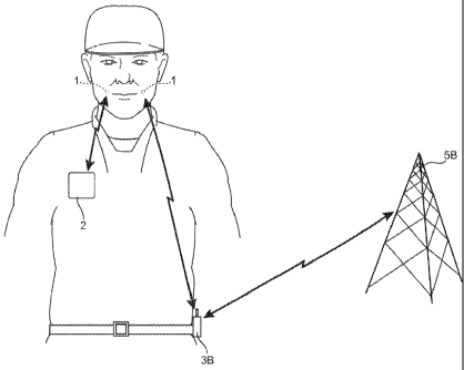
[00491 An exemplary wireless headset communication Sygem is shOwn in
...Figõ IC.
Referring now to Figs.1A-1D, the headset communication system includes a mouth
wearable
communicator I with a linking unit 8 such as a Bluetooth transceiver that
allows the communicator
I to play sound generated by a portable appliance or a sound source shown in
Fig, 1 A- 113 such as a
-
CA 02713350 2010-07-13
WO 2009/102889
PCT/US2009/033953
inusic player 2., a hands4ree communication device 3A or a cellular telephoue
3B, for example...
Altematively, the sound source can be a computer, a one-way communication
device, a two-way
communication device, or a wireless 'hands-free communication d.evice.
[00501 The mouth wearable communicator I can be a custom oral d.eviee.
The sound
source unit 2 or 3A or 38 contains a short-rang,e transceiver that. is
protocol compatible with the
linking. unit. For example, the sound source can have a Bluetooth transceiver
that communicates
with the Bluctooth transceiver linking unit 8 in the mouth wearable
communicator 1. The mouth
Avarable communicator can receive the data transmitted over the Bluetooth
protocol and drive a
bone conduction transducer 9 to render or transmit sound to the user.
[00511 The mouth wearable communicator can have a .microphone 6A embedded
therein.
The microphone 6A. can be an .intraoral microphone or an extraoral
microphone., For .cellular
telephones and other telephones, a second microphone 68 can be -used to cancel
environmental
noise and .transmit a user's voice to the telephone. .A noise canceller 7
receives signals from the
microphones 6A-6B and cancels ambient noise to provide a clean sound capture.
[00521 The two way communication device can have a microphone 6B to pick
up ambient
sound. The microphone 611 can be an intraoral microphone or an extraoral
microphone. In one
embodiment., the microphone cancels environmental noise and transmits a user's
voice to the
ternOtO station. This embodiment provides the ability to cancel environmental
noises while
transmitting subject's own -voice to the phone 3B which in turn communicates
with a remote base
station 513. As the microphone is in a fixed location (compared to ordinary
wireless communication
devices) and very close. to .user's own voice, the system can handle
.environmental noise reduction
that is important in working in high noise areas. As such, the headset of Fig.
.1.A or 18 can be used
by workers in loud environments such as a professional entertainer or athlete
andlor support
personnel, a soldier, a medic, a fireman, an emergency worker, among. others.
[0053] The mouth wearable communicator I can use a bone conduction
transducer ) or
any suitable bone conduction device. The mouth wearable communicator I can be
a custom oral
device. The mouth wearable communicator I can include a data storage device
with its content
encrypted. The device can include a 'housing having a shape which is
conformable to at least a
portion of at least one tooth.; an acruatable transducer disposed within or
upon the housing and .in
vibratory conununication with a surface of the at least one twill; and a -
wireless communication
transceiver coupled -to the transducer to pro-vide received soLmd to the user
and to provid.e
communication for the user. The 'headset can be an oral. appliance havingn
shape which confomis
to the at least one tooth. The communicator can include an electronic assembly
disposed within or
upon the housing and in communication with a transducer. The linking unit 8
can be a transceiver
compatible -with an 802 protocol, cellular protocol, or Biuetooth protocol. In
other embodiments,
the device provides an electronic and transducer device that can be attached.,
adhered., or otherwise
-.7 -
CA 02713350 2012-03-13
embedded into or upon a removable oral appliance or other oral device to form
a medical tag
containing patient identifiable information. Such an oral appliance may be a
custom-made device
fabricated from a thermal forming process utilizing a replicate model of a
dental structure obtained
by conventional dental impression and/or imaging methods. The electronic and
transducer
assembly may receive incoming sounds either directly or through a receiver to
process and amplify
the signals and transmit the processed sounds via a vibrating transducer
element coupled to a tooth
or other bone structure, such as the maxillary, mandibular, or palatine bone
structure.
[0054] The system couples microphones and voicing activity sensors to a
signal
processor. The processor executes a detection algorithm, and a denoising code
to minimize
background acoustic noise.
[0055] Two microphones 6A-6B are used, with the microphone 6A being the
bone
conduction microphone and which is considered the "signal" microphone. The
microphone 6B
captures air noise or ambient noise, whose signal is filtered and subtracted
from the signal in the
microphone 6A.
[0056] In one embodiment, the system runs an array algorithm for speech
detection that
uses the difference in frequency content between two microphones to calculate
a relationship
between the signals of the two microphones. As known in the art and discussed
in Patent No.
7246058, this embodiment can cancel noise without requiring a specific
orientation of the array
with respect to the signal.
[0057] In the embodiment of Fig. 1A, the linking unit in the communicator
1 can
communicate through Bluetooth with a one way or two way communication device
3A. The
device can be a music player or a hands-free voice communication system such
as a wallcie-talkie.
In another embodiment, the one-way or two-way communication device can be WiFi
VOIP system
that allows the user to communicate with others over a wireless local area
network through a
wireless LAN based server 5A. For example, the Vocera Communications System
can be used as
a wireless platform that provides hands-free, voice communication throughout
an 802.11b/g
networked building or campus. The system enables fluid, instant voice
conversations among team
members, across groups, and throughout an organization of mobile
professionals. The Vocera
Communications System consists of two key components: the Vocera System
Software that
controls and manages call activity, and the Vocera Communications Badge -
B2000 a lightweight,
voice-controlled communication device that allows users to converse over a
wireless LAN
(802.11b/g). Together, the Vocera System Software and Badge, allow users to
instantly
communicate with others throughout a building or campus environment. By using
the bone
conduction headset 1 with a hands-free voice system such as the Vocera system,
the user can
communicate sensitive patient information in confidence and thus allows the
user to meet the strict
requirement of patient privacy regulations such as HIPPA, for example.
- 8 -
CA 02713350 2010-07-13
WO 2009/102889 PCT/US2009/033953
[00:58.1 In the embodiment of fig. IB, the sound sourec.can ben cellular
telephone 3 that
communicates witha cellular base station 5BõAlternatively, the station 5B can
'be a satellite, a
cellular tower, a. relay station mounted on an airplane or a helicopter, or a
relay station mounted. on
a blimp, among others. Sound received by the cellular telephone 3B is sent via
Bluetooth to the
linking unit in the communicator 1,
10059.1 In one embodiment, the mouth wearable communicator has a housing
having a.
shape which is conformable to at least a portion ofat least enotooth
actnatable transducer
disposed within or upon the housing and in vibratory communication with a
sinface of the at least
one tooth; and a svireless communication transceiver coupled to the transducer
to provide received
sound to the user and to provide communication for the user. The two way
communication device
can be an oral appliance having a shape which conferms to the at least one
tooth. An electronic
assembly can be disposed within or upon the housing and which is in
conimunication with the
transducer.
10060] in another embodiment, the device l provides an electronic and
transducer device 9
that can be attached, adhered, or otherwise embedded into or upon a remova.ble
oral appliance or
other oral device to f01111 a medical tag containing patient identifiable
information.. Such an oral.
appliance may be a custom-made device fabricated from a thermal forming
process utilizing a
replicate model ola .dental :structure obtained by conventional dental
impression methods. The
electronic and transducer assembly may receive incoming sounds either directly
or through a
receiver to process and amplify the signals and transmit the processed sounds
via vibrating
transducer element coupled to a tooth or other bone structure, such as the
maxillary, mandibular, or
palatine bone structure.
[00611 in one embodiment. the -microphones can be place on each side of
the ears to
pro-vide noise cance]lation, optimal sound localization and directionality.
The microphones can be
pla.ced inside or outside the ears. For .example, the microphones can be
placed either at the opening
or directly with the user's ear canals. Each of the systems includes a
battery, a signal processor, a
transmitter, all of which can be positioned in a housing that clips onto the
ear which, rests behind
the ear between the pinna and the skull, or alternatively can be positioned in
the ear's concha. The
transmitter is connected to a wire/antenna that in turn .is connected to the
microphone.
[00621 Each transmitter transmits informatiou to a receiver that
activates a transducer that
is powered by a battery. Each side of the head can have one set of receiver,
transducer and battery.
This embodiment provides a bone conduction 'hearing aid device -with dual
externally located
microphones that are placed at the entrance to or in the ear canals and an
oral appliance containing'
dual transducers in communication with each other. The device will allow the
user to enjoy the
most natural sound input due to the location of the microphone which takes
advartme of the pirma
for optimal sound localization (and directionality).
- 9 -
CA 02713350 2010-07-13
WO 2009/102889 PCT/US2009/033953
[0063.1 anothetembodiment, the microphones receive sound.signals from
both sides of
the head, processes those signals to send a signal to the transducer on the
side:of the head where the
sound is perceived by the microphone to be at a 'higher sound level, A phase-
shifted signal is setn
to the transducer on the opposite side of the head. These sounds will then
"add." in the cochlea.
where the sound is louder and "cancel" on the opposite cochlea providing the
user with the
perception of directionality of the sound.
[0064 I In vet another embodiment, the .microphone at the first ear
receives sound signals
:from the first side of the head, processes those signal to send a. signal to
the transducer on that same
or first side of the oral appliance. A second microphone at the second ear
receives a sound signal
that is lower in amplitude and delayed in respect to the sound sensed by the
first microphone due to
head shadowing and. physical separation of the microphones, and sends a
corresponding signal to
the second transducer on the second side of the oral appliance.. The sound
signals from the
transducers will be perceived by each cochlea on each side of the head as
being different in
amplitude and phase, which will result in the perception of directionality by
the user.
[00651 Figs, 2-3 show in more d.etail one exemplary mountinu of hearing
system 1 with
the microphone 7 in the user's ear canal. As shown therein, the components
such as the battery 3,
the signal processor 4, and the transmitter 5 can either be located behind the
ear or within the .folds
of the pinna. The human auricle is an almost .rudimentary, usually immobile
shell that lies close to
the side of the head with a thin plate of yellow fibrocartilagc covered by
closely adherent skin. The
cartilage is molded into clearly defined hollows, ridges, and furrows that
.forin an irregular, shallow
ftinnel. The deepest depression, which leads directly to the external auditor
y canal, or acoustic
meatus, .is called the concha. It is partly covered by two small projections,
the tonguelike tragus in
front and the antitratnis behind. Above the trims a prominent ridge., the
helix, wises from the floor
of the concha and continues as the incurved rim of the upper portion of the
auricle. An inner,
concentric ridge, the antihelix, surrounds the concha and is separated from
the helix by a furrow,
the seapha, also called the fossa of the helix.. The lobule, the .fleshy lower
part of the auricle., is the
only area of the outer ear that contains no cartilaue. 'The auricle also has
several small rudimentary
muscles, which ilisten it to the skull and scalp. ln most individuals these
muscles do not function,
although some persons can voluntarily activate them to produce limited
movements. The external
auditory canal is a slightly curved tube that extends inward from the floor of
the concha and ends
blindly at the tympanic membrane. In its outer third the wall of the canal
consists of cartilage; in its
inner two-thirds, of hone. The anthelix (antihelix) is a. folded "Y" shaped
part of the ear. The
antitragus is the lower Cartilaginous edge of the .eonchal bowl just above the
fleshy lobule of the
car.
[00661 As best shown in. Fig. 3, the microphone 7 is positioned in the
ear canal. The
microphone 7 is connected with the transmitter 5 through the wire and antenna
6. The placement of
- 10 -
CA 02713350 2010-07-13
WO 2009/102889 PCT/US2009/033953
the mierophone7inside the ear provides tile user with the most :natural
sound input due to the
location of the microphone which takes .advantageof the pirtna for optimtl.
sound localization and
directionality) when the sound.s are transmitted to the cochlea using a
straight signal and "phase-
Shifted." signal to apply directionality to the patient. High quality sound
input is captured by
placing the microphones within or at the entrance of the ear canal which would
allow the patient to
use the sound reflectivity of the pinna as well as improved sound
.diroctionality due to the
microphone placement. The arrangement avoids the .need to separate the
microphone and speaker
to reduce the chance of feedback and allows placement of the microphone to
take advantage of the
sound reflectivity of the pinna... The system also allows for better sound
directionality due to the
two bone conduction transducers being in electrical contact with each other.
With the processing of
the signals prior to 'being sent to the transducers and the transducers able
to COMIMIlliCate With each
other, the system provides the best sound localization possible.
[0067] The mouth wearable communicator can provide a data storage device
such as a
solid state memory or a flash storage device. The content of the data storage
device can be
encrypted fir security, The Finking. unit can transmit encrypted data for sec=
transmission if
desired..
1.00681 Inming now to inore details on the device I_ as shown in Fig,. ID,
a patienf,s
.mouth and dentition 10 is illustrated showing one possible location for
removably attaching two-
way conummication assembly 14 upon or against at least ono tooth, such as. a
molar 12. The
patient's tongue TG and palate Pt are also illustrated for reference. .Ati
electronics andlor
transducer assembly 16 may be attached, adhered, or otherwise embedded into or
upon the
assembly 14, as described below in further detail.
[00691 Fig, 2A shows a perspective view of the patient's lower dentition
illustrating the
two-way communication assembly 14 comprising a removable oral appliance 18 and
the electronics
and/or transducer assembly 1.6 positioned along a side surface of the assembly
14_ In this variation,
oral appliance 18 may be fitted upon two molars .12 within tooth engaging.
channel 20 defined by
oral appliance 1.8 kw stability upon the patient's teeth, although in other
vaiiations, a single molar
or tooth may be utilizedõAlternatively, more than two molars may be utilized
for the oral appliance
18 to be attached upon or over. N4oreover, electronics and/or transducer
assembly 1.6 is shown.
positioned upon a side surface of oral appliance 18 such that the assembly 16
is aligned along a.
buccal surface of the tooth. 12; however, other surfaces such as he lingual
surface of the tooth 12
and other positions :nay also be utilized. The figures are illustrative of
variations and are not
intended to be limiting; accordingly, other .configurations and shapes for
oral appliance 18 are
intended to be included herein.
[00701 Fit4.. 2B shows another variation of a reinova.ble oral appliance
in the form of an
appliance 15 which is placed over an entire row of teeth in the manner of a
mouthituard, in this
- 11 -
CA 02713350 2010-07-13
WO 2009/102889 PCT/US2009/033953
variatio4, appliance 15 may be confignred to roverm entire bottom row of teeth
or alternatively an
entire upper row of teeth. In additiond variations, rather than coming the
entire rows of teeth, a.
majority of the row of teeth may be instead be covered by appliane.e 15.
Assembly 16 may be
positioned along one or more portions of the oral appliance 15.
10071.1 Fig. 2C shows yet another variation of an oral appliance 17 having
an arched
configuration. lri this appliance, one or .morc tooth retaining portions .21,
23, which in this variation
.may be placed along the upper row of teeth, .may be supported by an arch 19
which .may lie
adjacent or along the palate of the user. As shown, electronics andfor
transducer a.ssembly 16 may
be positioned along one or more portions of the tooth retaining portions 2:1.,
23. 'Moreover,
although the variation shown illustrates asn arch 19 which may cover only a
portion of the palate of
the user, other variations may be configured to have an arch which covers the
entire palate of the,
user.
[00721 flit. 2D illustrates yet another 'variation of an oral appliance
in the form of a
mouthguard or retainer 25 which may be inserted and removed caSily from the
user's mouth. Such
mouthguard or retainer 25 may" be used in sports where conventional
mouthguards are wom,
however, mouthguard. or retainer 25 having. assembly 16 integrated therein may
be utilized bv.
persons, hearing impaired or otherwise, who may simply hold the mouthguard or
retainer 25 via
grooves or channels 26 between their teeth for reeeivin.g, instructions
remotely and eonuminicating
over a .distance.
100731 Generally, the volume of electronics andior transducer a.ssembly
16 inay he
minimized so as to be unobtrusive and as comfortable to the user when placed
in the mouth.
Although the size may be varied, a volume of assembly 16 may be less than NO
cubic .millimeters.
'This volume is, of course, illustrative and not limiting as size and. -volume
of assembly 16 and may
be varied accordinuly between different -users.
[00741 -Moreover, removable oral appliance 18 may he fabricated from
various polymeric
or a combination of polymeric and metallic materials using any number of
.methods, such as
computer-aided machining processes 'using computer numerical control (CC)
systems or three-
dimensional printing processes, e.g., stereolithography apparatus (SLA),
selectiw laser sintering
(StS), and/or other similar processes utilizing three-dimensional geometry of
the patient's
dentition, which .may be obtained via any number of techniques. Such
techniques may .include use
of scanned .dentition using intra-oral scanners such as laser, white light,
ultrasound, mechanical
three-dimensional touch scanners, magnetic resonance imaging (MR.1.), computed
tomography
(ff), other optical methods, etc.
[00751 in forming the removable oral: appliance 18, the appliance 18 may
be optionally
formed such that it is molded to fit over the dentition and at least a portion
of the adjacent gingival
tissue to inhibit the entry of food, fluids., and other debris into the oral
appliance 18 and between the
- 12-
CA 02713350 2010-07-13
WO 2009/102889 PCT/US2009/033953
transducer :assembly and tooth surface. Mo.reover, the greater surface area of
the oral appliance 18
may facilitate the placement and confruuration of theassembly 16 onto the
appliance 18,
[00761 Additionally, the removable oral appliance 18 niay be optionally
:fabricate] to have
a shrinkage factor such that -when placed. onto the dentition, oral appliance
18 may be configured to
securely grab onto the tooth or teeth as the appliance 18 may have a resulting
size slightly' smaller
than the scanned tooth or teeth -upon \VhiCh the ;Appliance 18 was thrilled.
The fitting 'nay result in
a secure interference fit between the appliance 18 and underlying. dentition,
[0077] 1n one variation, with assembly 14 positioned upon the teeth, as
shown in Fig_ 3, an
extra-buccal transmitter assembly 22 located outside the patient's mouth may
he utilized to receive
auditory signals for processing and transmission via a wireless signal 24 to
the electronics ad/or
transdueer assenibly 16 positioned within the patient's mouth, which May then
process and transmit
the processed auditoiy signals via vibratory conductance to the underlying
tooth and consequently
to the patient's inner ear.
10078] The transmitter 'assembly 22, as described in further detail
below, may contain a
microphone assembly as well as a transmitter assembly and may be configured in
any number of
Shapes and ibrins -worn by the user, such as a watch, necklace, lapel, phone,
belt-mounted device,
etc.
[00791. .
Fig.. 4 illustrates a schematic representation ot one variation of two-way
communication assembly 14 utilizing an 4-:,xtra-buccal transmitter
asseinbly22:, which may
generally comprise microphone 30 for .receiving sounds and which is
electrically connected to
processor 32 for processing. the auditor y signals. Processor 32 may be
connected dectrically to
transmitter 34 for trans.mitting the processed signals to the electronics
and/or transducer assembly
16 disposed upon or adjacent to the user's teeth. The microphone 30 and
processor 32 may be
configured to detect and process auditory signals in any practicable range,
but may be configured in
one variation to detect. auditory signals ranging from, e.g., 250 Hertz to
20,000 Hertz.
[00801 With respect to microphone 30, a variety of various mic.mplione
systems may be
utilized.. For instance, microphone 3.0 may be a digital, analog, andfor
directional type microphone.
Such various types of microphones may be interchangeably configured to be
utilized. \vitt' the
assembly, if so desired.
10081.1 Power :supply 36 may be connected to.cach of -the components in
transmitter
assembly 22 to provide power thereto. The iranstnitter sigta1s'24 auty be in
any -wireless f01111
utilizing', e.g., radio frequency, ultrasound, microwa.ve, Blue Tooth
(BLUETOOTH S1(I,
Bellevue, WA), etc. for transmission to assembly 16. .Assembly 22 may also
optionally include one
or more input controls 28 that a user may manipulate to adjust various
acoustic parameters of the
electronics and/or transducer assembly 16, such as acoustic ibcusina, -volume
control, filtration,
mutinu, frequency optimization, sound adjustments, and tone adjustments, etc.
CA 02713350 2010-07-13
WO 2009/102889 PCT/US2009/033953
[0082.1 The.signals transmitted 24 by transmitter 34 may her eceived by
electronics andior
transducer assembly 16 via receiver 38. Which may be connected to an internal
processor for
additional processing of the received. signals. The received signals may be
communicated to
transducer 40, which inay -vibrate correspondingly against a surface of the
tooth to conduct the
vibratory signals through the tooth and bone and subsequently to the middle
ear to facilitate hearing
of die user. Transducer 40 .may he configured as any number of different
vibratory mechanisms.
For instance, in one -variation, transducer 40 may be an electromagnetically
actuated transducer. In
other variations, transducer 40 may be in the =form of a piezoelectric crystal
having a range of
vibratory frequencies, e.g., between 250 to 4000 Hz.
10083] Power supply 42 may also be included with assembly .I.6 to provide
power to the
receiver, transducer, andlor processor, if aIso included. Although power
supply. 421-nay be a simple
battery, replaceable or permanent, other variations may include a power supply
42 which is charged
by inductance via an external charger, Additionally, power supply 42 may
alternatively be charged
via direct coupling to an ahcmatina current (AC) or .direct current (DC)
source. Other variations
may- inciude a power supply 42 which is charged via a mechanical mechanism,
such as an internal
pendulum or slidable electrical inductance charger as known in =the art, which
is actuated. via, ex.,
motions of the jaw and/or movement for translating the mechanical motion into
stored electrical
energy for charging power supply 42.
[00841 another variation of assembly 16, rather than utilizing, an extra-
buccal
transmitter, two-way communication assembly 50 niay be configured as an
independent assembly
contained entirely within the user's mouth, as shown in Fig. 5. Accordingly,
assembly 50 may
include an internal microphone 52 in communication with an on-board processor
54. Internal
microphone 52 may comprise any number of:different types of niicrophones, as
described above.
Processor 54 may be used to process any received auditory signals for
filtering andlor amplifying
the signals and transrnitting therm to transducer 56, which .is in vibratory
contact against the tooth
surface. Power supply. 58, as described above, may also be .included within
assembly 50 for
providing power to each of the components of assem.bly 50 as necessary.
[00851 In order to transmit the vibrations corresponding to the received
auditory signals
efficiently and with minimal loss to the tooth or teeth, secure mechanical
contact between the
transducer and the tooth is ideally maintained to ensure efficient vibratory
communication.
Accordingly, any .number of mechanisms may be =atilized to maintain this
vibratory communication.
[0086j In one variation as shown in Fig. 6A, a. partial cross-sectional -
view of a removable
oral. appliance 60 is ShOWil placed over or upon a tooth TH. Electronics
and/or transducer housing
62. may be seen defined along oral appliance 60 such that housing 62. is
aligned or positioned
adjacent to a side surface, buccal and/or lingual surface, of the tooth TH.
Housing 62 may proyi.d.e
protection to the electronics and/or transducer assembly from the environment
of the mouth,
-14 -
CA 02713350 2010-07-13
WO 2009/102889 PCT/US2009/033953
[00871 An electronics and/or transducer assembly 64 may Ix simply placed,
embedded, or
encapsulated within housing 62 for contacting the tooth surface, In this
variation, assembly 64 may
be adhered against the tooth surface via an adhesive surface or film 66 such
that contact is
maintained between the two. As Shown in Eig. 6B, a removable backing 68 may be
adhered onto
adhesive surface 66 and removed prior to placement upon the tooth surface. In
this manner,
assembly 64 may be replaced upon the tooth aS necessary with additional
electronics and/or
transducer 3SSem1lies.
100881 Aside from an adhesive film 66, another alternative may utilize an
expandable or
sellable member to ensure a secure mechanical contact of the transducer
against the tooth. As
shown in Fig. 7, an osmotic patch or expandable hydrogel 74 may be placed
between housing 62
and electronics and/or transducer assenibly 72. After placement of oral
appliance 60, hydrogel 74
May abSOit Mlle fluids, either from any surrounding fluid or from a fluid
introduced into hydrogel
74, such that hydrogel 74 expands in size to force assembly 72 into contact
against the tooth
surface. Assembly 72 may he configured to define a contact surface 70 having a
relatively smaller
contact area to facilitate uniform contact of the surface 7ti against the
tooth. Such a contact surface
70 may be included in any of the variations described herein. Additionally, a
thin encapsulating
layer or surface 76 may be placed over housing 62 between contact. surface 70
and the underlying
tooth to prevent any debris or additional fluids frorn entering, housing 62.
[00891 Another variation is shown in Fig. 8, which shows electronics
and/or transducer
assembly 80 contained within housing 62. In this variation, one or more
biasing elements 82, e.g.,.
springs, pre-formed shape memory elements, etc., may be placed between
assembly 80 and housing
62 to provide a pressing, force on assembly 80 to urge the device against the
underlying tooth
surface, thereby ensuring mechanical contact.
[00901 in yet another variation, the electronics may be contained as a.
separate assembly 90
which ìs encapsulated within housing 62 and the transducer 92 may be
maintained separately from
assembly 90 but also within housing 62. As shown in Fig. 9, transducer 92 may
be urged against
the tooth surface via. a spring or other biasing element 94 and actuated via
any of the mechanisms
described above.
100911 in other variations as shown in Fig. 10, electronics andior
transducer assembly :100
may be configured to have a ramped surface 102 in apposition to the tooth
surface. The surface
102 may be angled away from the occlusal surface of the tooth. The assembly
100 may be urged
via a biasing element or spring 106 which forces the ramped surface 102 to
pivot about a location
104 into contact against the tooth to ensure contact for the transducer
against the tooth surface.
100921 Fig. 1-1 illustrates another simiktr variation ì.n electronics
and/or transducer
assembly 110 aiso having a ramped surface 112 in apposition to the tooth
s.urface, in this variation,
the ramped surface 112 may be angled towards the occlusal surface of the
tooth. Likewise,
-
CA 02713350 2010-07-13
WO 2009/102889 PCT/US2009/033953
assembly 1.1.0 may be -urged. via a biasing element or spring 116 which urges
the assem b y 1.10 to
pivot about its lower end such that the assembly 110 contacts the tooth
surface at tt region .114.
[00931 In yet another variation shown in Fig. 12, electronics andlor
transducer assembly
120 may- be positioned within housing 62 with an intetface layer 122
positioned between the
assembly 1.20 and the tooth surface. Interface layer 122 may be configured to
conform against the
tooth surface and against assembly 120 such that vibrations may be transmitted
through layer 122
and to -the tooth in a uniform manner. Accordingly, interface layer 122 may be
made from rr
material which attenuates vibrations minimally. Interface layer 122 may be
made in a variety of
forms, such as a simple insert, an 0-ring configuration, etc. or even in a gel
or paste form, such as
denture .or oral paste, etc. .Additionally, layer 122 may he fabricated from
various materials, e.g.,
hard plastics or polymeric materials, metals, etc_
[0094j Fig. .13 illustrates yet another variation in which electronics
andlor transducer
assembly 130 may be urged against the tooth surface via a. mechanical
mechanism. As shown,
assembly 130 may be attached to a structural member 132, e.g., a threaded
member or a simple
shaft, which is connected through housing 62 to an engagement member 134
located ontsid.e
housing 62. The user may -rotate engagernent mem.ber 134 (as indicated by
rotational arrow 136) or
simply push upon member 134 (as indicated by linear arrow 138) to urge
assembly 130 into contact
against the tooth. :Moreover, actuation of engagetnent member 134 may be
accomplished manually
within the mouth or through the user's ehee.k or even through .manipulation
via the user's -tongue
against engagement member 134.
[00951 Another variation for a mechanical mechanisni is illustrated in
Fig. ]l. In this
variation, electronics and/or transducer assembly 140 may define a portion
asau .engaging surface
142 for contacting against a. cam or lever mechanism 144. Cain or lever
mechanism 144 may be
configured to pivot 46 such that actuation of a. lever 148 extending through
housing 62 may urge
cam or lever mechanism 144 to push against engaging surface 142 such that
assembly 140 is
pressed against the underlying, tooth surface,
[00961 in yet another variation, the electronics 150 and the transducer
152 may be
separated from one another such that electronics 150 remain disposed. -within
housing, 62 but
transducer 152, connected via. wire 154, is located beneath dental oral
appliance 60 along an
occlusal surface of the tooth, as shown in Fig. 15. 11.1 such a.
conlioaration, -vibrations are
transmitted via the transducer 152 through the occlusal surface of the tooth.
Additionally, the user
ma.y bite down upon the oral appliance 60 and transducer :152 to mechanically
compress the
transducer 152 against the occlusal surface to ftather enhance the mechanicai
contact between the
transducer 152 and underlying tooth to further facilitate transmission
therethrough.
[0097j In the -variation of Fin, 16, another cx.ample for a 'bite-
enhanced coupling
mechanism is illustrated where electronics and/or transducer assembly 160
defines an angled
-16 -
CA 02713350 2010-07-13
WO 2009/102889 PCT/US2009/033953
interface surface 162 ip apposition to a. correspondingly angled engaging
member 164.. A proximal
end dengaging member 164 may:extend -through housing 62 and terminate in a
pusher member
166 positioned over an occlusal surface of the tooth TH. Once oral appliance
60 is initially placed
over =tooth TH, the user may bite down or otherwise press down upon the top
portion dotal
appliance 60, thereby pressing down .upon pusher member 166 which in turn
pushes down upon.
engaging .member 164, as indicated by the arrow. As engaging,..member 164 is
urged downwardly
towards the gums, its angled surface may push upon the corresponding and
oppositely angled
surface 162 to urge assembly 160 against the tooth surface and into a. secure
mechanical contact.
10098 I In yet another variation, an electronics andfor transducer
assembly 170 may define
a channel or -._;:roove 172 along a surface for engaging a corresponding -
dental anchor 174, as shown
in Fig.. 17, Dental anchor 174 may comprise a light-curable acrylate-based
composite material
adhered directly to the tooth surface. Moreover dental anchor 174 .may be
configured in a. shape
which corresponds to a shape of channel or groove .172- such that the two may
be interlined in a
mating- engagement. In this manner, the transducer in assembly 1.70 may
vibrate directly against
dental anchor 174 which may then transmit these signals direetly into the
tooth 'TH.
[00991 Figs. 18A and 1813 show partial. cross-sectional side and top
views, respectively, of
another variation in vhich oral appliance 180 inay define a. number of
.channels or grooves .184
along a top portion of oral appliance 180. Within these channels or grooves
184, one or .more
transducers 182, 186,188, 190 may be disposed such that they are in contact
with the occlusal
surface of the woth and each of these transducers may be tuned w transmit
frequencies uniformly.
Alternatively, each of these transducers may be tuned to transmit only at
specified frequency
ranges. Accordingly, each transducer can be programmed or preset for a
different frequency
response such that each transducer may be optimized for a different frequency
response andfor
transmission to deliver a relatively high-fidelity sound to the user,
[01001 In yet another variation, Figs. 19A and 1913 illustrate an oral
appliance :200 which
may be pre-formed from a shape memory polymer or alloy or a super-elastic
material such as a
Nickel-Titanium alloy, e.g.,. Nitinol. Fig. 19A shows oral appliance 200 in a
first configuration
where inentbers 202, 204 are in an unbiased memory configuration. When placed
upon or against
the tooth THõ .members 202, 204 may be deflected into a second configuration
'here members
202, 204' are deformed to engage tooth TH in a secure intcrference fit, as
ShOW11 in Fig. 1913, The
biased .member 204' may be utilized to press the electronics and/or transduc-
er assembly contained
therein against the tooth surface as well as to maintain securernent of the
oral appliance 200 upon
the tooth Tit.
101011 Similarly, as shown in Fig, 20, removable oral appliance 210 may
have biased
members to secure engage the tooth TH, as above. irì this variation, the end.s
of the members. 212,
214 may be configured into curved portions under which a transducer element
218 coupled to
-17 -
CA 02713350 2010-07-13
WO 2009/102889 PCT/US2009/033953
electronics.asserably 2.16 may be wedged or Othei*SeSeCtIred to ensure
mechanical contact against
the tooth surface.
[01021 Fig. 21 shows yet another variation in vhicli the oral appliance
is omitted entirely.
Her, a composite dental anchor or bracket 226, as described above, may be
adhered directly onto
the tooth surface. Alternatively, brack_et 226 may be comprised of a
bioeompatible material,
stainless steel, Nickel-Titanium, Nickel, ceramics, composites, etc., thrilled
into a bracket and
anchored onto the tooth surface. The bracket 226 may be configured to have a
shape 228 over
which an electronics andfor transducer assembly 220 naay be slid over or upon
via a channel 222
having a. corresponding receiving configuration 224 for engagement with
bra_eket 226. In this
manner, asse.mbly 220 may be directly engaged against bracket 226, through
which a transducer
may directly vibrate into the underlying tooth TH. Additionally, in the event
that assembly 220 is
removed from the tooth TH,. assembly 220 may he simply slid or rotated off
bracket 226 and a
replacement assembly .may be put in its place upon bracket 226.
[01031 Figs. 22A and 228 show partial cross-sectional side and
perspective views,
respectively, of yet another vwlation of an oral appliance 230, In this
variation, the oral appliance
230 may- be configured to omit an occlusal surface portion of the oral
appliance 230 and instead
engages the side surfaces of the tooth TH.. SUCh as the lingual and 'buccal
surfaces only. 'The
electronics andlor transducer assembly 234 may be contained, as above, within
a housing 232 for
contact against the tooth surface. Additionally, as shown in Fig. 22. one or
more optional cross-
members 236 may connect the side portions of the oral appliance 230 to provide
some structural
stability when placed upon the tooth. This variation may define an occlusal
surface opening 238
such that when placed upon the tooth, the user may freely. bite down directly
upon the natural
occlusal surface of the tooth unobstructed by the oral appliance. device,
.thereby providing for
enhanced cotnibrt to the user.
101041 In yet other variations, vibrations may be transmitted directly
into the underlying
bone or tissue structures rather than transmitting directly through the tooth
or teeth of the user. As
shown in Fig, 23A, an oral appliance 240 is illustrated. positioned upon the
user's tooth, in this
example upon a molar located along the upper row of teeth, 'The electronics
andior transducer
assembly 242 is shown as being located along the buccal surface .of the tooth.
'Rather than utilizing
a transducer in contact with the tooth surface, a conduction transmission
.member 244, such as a
rigid or solid .metallic member, may be coupled to the transducer in assembly
242 and_ extend .frotn
oral appliance 240 to a post or screw 246 which is implanted directly .into
the underlying bone 248,
such as the _maxillary bone, as shown .in the partial cross-sectional vim of
Fig. 2313. A.s the distal
end of transmission member 244 is coupled directly to post or screw 246, the
vibrations generated
by the transducer may be .transmitted through traasmissioa member 244 and
directly into post or
- 18 -
CA 02713350 2010-07-13
WO 2009/102889 PCT/US2009/033953
.$crcw 246, which in aim trapsinits the vibrations directly into and througli
the bone 248 for
transmission to the user's inner ear.
[01051 Fig. 24 illustrates a partial cross-sectional .yiewof an oral
appliance 250 placed
upon the user's tooth TH with the electronics and/or transducer assembly 252
located alont7, the
lingual surface of the tooth. Similarly, the vibrations may he transmitted
through the conduction
transmission member 244 and directly into post or screw 246, which in this
example is implanted
into the 'palatine bone PL. Other variations .may utilize this arrangement
located along the lower
row of teeth for transmission to a post or screw 246 drilled into the
:mandibular bone.
[0106] in yet another variation, rather .utilizing a post or screw
drilled into the underlying
bone itself, a transducer may be attaehed, coupled, or otherwise adhered
directly to the gingival
tissue: surface adjacent to the teeth. As shown in Figs, 25A and 258, an oral
appliance 260 may
have an electronics assembly 262 positioned along its side with an electrical
wire 264 extending.
therefrom to a transducer assembly 266 attached to the gingival tissue surface
268 next to the tooth
TH. Transducer assembly 266 may be attached to the tissue surface 268 via an
adhesive, structural.
support arm extending from oral appliance 260, a dental screw or post, or any
other structural
mechanism In use, .the transducer may vibrate and =transmit directly into the
underlying gingival
tissue, which may .conduct the signals to the underlying bone,
101071 For any of the -variations described above, they may be utilized
as a single device
or in combination with any :other variation herein, as practicable, to achieve
the desired hearing
level in the user. !Moreover, more than one oral appliance device and
electronics andior transducer
assemblies may be utilized at any one time. For example, Fig. 26 illustrates
one example where
multiple transducer assemblies 270, 272, 274, 276 may be placed on .multiple
teeth, Although
Shown on the lower row of teeth, multiple assemblies may alternatively be
positioned and 'located
along the upper row of teeth or both rows as well. Moreover, each of the
assemblies may be
configured to transmit vibrations within a uniform .frequency range.
Alternatively in other
variations, different assemblies may be configured to vibrate within non-
overlapping frequency
ranges between each assenably. As -mentioned above, each transducer 270, 272,
274, 276 can be
programmed or preset for a different frequency response such that each
transducer may be
optimized for a different frequency response andlor transmission to deliver a
relatively high-.fidelity
sound to the user.
[01081 Moreover, each of the different transducers 270, 272, 274, 276 can
also be
programmed to vibrate in a manner which indicates the directionality of SOMA
received by the
microphone worn by the user. For example, different transducers positioned at
different locations
within the user's mouth can vibrate in a specified manner by providint4 sound
or vibrational queues.
to inibrm the user v-hi.e.171 direction a sound was d.etected relative to an
orientation of the user. For
instance, a first transducer located, e.g., on a user's left tooth, can be
programmed to vibrate for
-
CA 02713350 2010-07-13
WO 2009/102889 PCT/US2009/033953
.sound detected originating from the nser'Slcft side. SirPilarlyõ.a..second.
transducer located, e.g.,, .on
a user's right tooth, can be programmed to V ib ra t e for sound detected
originating from the user's
right side Other variations and queues may be utilized as these examples are
intended to be
illustrative of potential variations,
101091 hi variations Where the one or more microphone.s are positioned in
intra-buccal
locations, the microphone may be integrated directly into the electronics
and/or transducer
assembly, as described above. However, in additional variation, the
microphone, unit may be
positioned at a distance from the transducer assemblies to minimize :feedback.
In one example,
similar to a variation shown above, microphone unit 282 may be separated from
electronics and/or
transducer assembly 280, as shown in Figs. 27A and .27B. In such a variation,
the microphone. unit
282 positioned .upon or adjacent to the gingival surface 268 may be
electrically connected via.
wire(s) 264.
10110I Although the variation illustrates the microphone unit 282 placed
adjacent to the
gingival tissue 268, unit 282 may be positioned npon.another tooth or another
location. yvithin the
mouth. For instance., Fig. 28 illustrates another variation 290 vhiehutilizes
an arch 19 connecting
one or more .tooth retaininu portions 21, 23, as described above, _However, in
this variation, the
microphone unit .294 may be integrated within or upon the arch. 19 separated
from the transducer
assembly 292. .0ne or .more wires 296 routed through arch 19 may electrically
connect the
.microphone unit 294 to the assembly 292. Alternatively, .rather than
utilizing a wire 296,
microphone unit 294 and assembly 292 may be wirelessly coupled to 00C another,
as described
above.
1011.1.] in yet another .variation for separation the microphone from the
transducer
assembly, Fig. 29 illustrates another variation -where at Ieast one microphone
302 (or optionally any
number of additional microphones. 304, 306) a:lay be positioned vithin the
mouth of the user while
physically separated from the electronics andlor transducer assembly 30t1 In
this manner, the one
or optionally more miemphones 302, 304, 306 may be wirelessly coupled to the
electronics andfor
transducer assembly 300 in a manner which attenuates or eliminates feedback,
if present, from the
transducer,
[01.121 'The applications of the devices and methods discussed above are
not limited to the
treannent of hearing loss but may include any .t.rumber of .further treatment
applications. Moreover,
such devices and .methods may be applied to other treatment sites within the
body. Modification of
the above-described assemblies and methods for carrying out the invention,
combinations between
different variations as practicable, and variations of aspects of the
invention that are obvious to
those of skill in the art are intended to be within the scope of the claims.
- 20 -