Note: Descriptions are shown in the official language in which they were submitted.
CA 02713895 2010-07-30
WO 2009/103975 PCT/GB2009/000452
MOBILE SUBSTRATE ATTACHMENT DEVICE
This application claims priority to UK patent application No. 0803059.5 filed
on 20 February 2008 entitled "Mobile Substrate Attachment Device" , the
entire contents of which are hereby incorporated by reference.
FIELD OF THE INVENTION
The invention relates generally to extensible, flexible devices for
attachment to mobile , surfaces, thereby enabling, for example, the
attachment of non-extensible, inflexible devices to mobile surfaces.
BACKGROUND TO INVENTION
Attachment of one object to another via a contact surface is a paradigm for
the assembly of multiple component systems. The adjoining components
can be naturally or synthetically derived and may be alive, dead or
inanimate matter. Common joining methods belong to one of two large
families: adhesive and mechanical. Adhesives include chemical reaction
adhesives (e.g. cyanoacrylates, anaerobics, acrylics, epoxies,
polyurethanes, polyimides, phenolics and silicones) and physical reaction
(e.g. hot-melts, plastisols, rubbers, PVAs and , pressure sensitives)
adhesives. Mechanical methods include interpenetrating, interlocking and
interference mechanisms (e.g. riveting, bolting, screwing, nailing, jointing,
zipping, stitching, buttoning, hook-and loop-fastening and suction). It can
be generalised from these examples that adhesive methods and
mechanical methods are commonly applied to join physically inflexible
objects together. Meanwhile, for highly flexible materials like fabrics,
mechanical methods dominate.
Against this background, it is perhaps not surprising that mechanical
methods of attachment dominate medical practices concerning soft tissues
(suturing, stapling). Even for attachment to hard tissue, a strong
mechanical element is maintained (interference fit of screws and nails into
bone, dental and bone cements). The use of medical adhesives for the
joining of tissue is very limited in comparison to mechanical methods. An
1
CA 02713895 2010-07-30
WO 2009/103975 PCT/GB2009/000452
exception to this is in the application of devices to the human skin: such
devices, including drug delivery patches, wound dressings and ostomy
pouches, are conventionally attached using adhesives. This is because
these devices rarely remain in place for extended periods and also
because currently available mechanical attachment methods are
considered too painful (e.g. staples) for non-surgical applications.
The mechanical joining of soft tissue by current methods is not ideal
because. the materials applied (e.g. nylon sutures, metal staples) are not
mechanically well matched to the tissue(s) being joined. The mechanical
mismatch creates anisotropic and unnatural forces within the tissues and
can cause local tissue death and further complications (e.g. site for
bacterial colonisation). Similarly, the adhesive joining of soft tissues or
the
adhesive attachment of devices to the skin by current methods is not ideal
because of mechanical mismatching. For example, topical devices on the
skin frequently become dislodged before the end of use.
In conclusion, current paradigms for the joining of soft tissues or
attachment to soft tissues are mechanically mismatched to the tissues to
which they are applied; this leads to abnormal mechanical loading and
either device failure, tissue damage or both. The purpose of this invention
is the re-design of the interface of attachment to soft tissue. The starting
point for re-examination is an understanding of the mechanics of soft tissue
itself. Key to our insight is the fact that soft tissue is unusual because, in
contrast to most man-made materials, it is flexible, not very stretchy but
highly mobile. These properties are the result of the geometry and
multilaminate construction of our soft tissues, particularly the skin. It is
common misconception that skin is stretchy; skin is not very stretchy, as
new mothers and crash dieters can attest to. Our skin is however mobile
because we carry an excess area of it to accommodate our body's
extensive range of movement.
Woven, non-woven and knitted materials provide good examples of man-
made constructs that can exhibit similar properties to soft tissue, hence
their extensive use in clothing. Our clothing, able to slide freely on the
surface of our skin, forms a loose bilarninate on our surface, localised by
2
CA 02713895 2010-07-30
WO 2009/103975 PCT/GB2009/000452
topological constraint; this is not unlike our skin, which can itself become
separated from the body due to high shear trauma. The attachment of
small devices to the skin does not require attachment to a bespoke
undergarment; circumferential bands can' meet some of these needs but
attachment of devices to the torso requires an alternative strategy. The
need to be able to position a portable device to any location of the human
body necessitated the use of pressure sensitive adhesives, of the sort
used on Band-AidTM or ElastoplastTM. The application of such adhesives
to medical devices for topical attachment can still lead to complications of
mechanical mismatching, for example shear-force blistering.
The present invention provides an extensible, flexible device for
attachment to mobile surfaces; including the attachment of non-extensible.,
inflexible devices to mobile surfaces.
SUMMARY OF INVENTION
The principle of the invention is to construct a device. having a surface that
it is capable of the same or greater extension and flexibility than the
substrate to which it is attached. This is achieved by utilising a device
having a surface with discontinuous contact points. The contact points,
which contact only a small percentage of the substrate, are connected by a
device surface path length in excess of that which can be generated
between the same points on the flexible substrate.
Thus according to a first aspect of the invention there is provided an
attachment device having a substrate facing surface, wherein the substrate
facing surface is provided with at least one flexible protrusion extending
therefrom, said protrusion forming a flexible bridge between the substrate
facing surface and a flexible substrate.
This aspect of this invention concerns a device for attachment to a flexible
substrate. Here the word `flexible' is used to describe mobile, extensible,
flexible substrates.
=
3
CA 02713895 2010-07-30
WO 2009/103975 PCT/GB2009/000452
The device may be used to join two or more spatially separated surfaces,
at least one of which is a flexible.
The device may be used to join two or more spatially separated surfaces,
at least two of which are flexible. As such in an embodiment of the
invention the attachment device is provided with a first substrate facing
surface and a second substrate facing surface, wherein both substrate
facing surfaces are provided with at least one flexible protrusion extending
therefrom, said protrusion forming a flexible bridge between the first
substrate facing surface and a first flexible substrate and between the
second substrate facing surface and a second flexible substrate.
In embodiments of the invention the flexible surfaces may be internal or
external surfaces of the human or animal body. For example, surfaces of
soft tissues. The term soft tissue refers to tissues that connect, support, or
surround other structures and organs of the body. Soft tissue includes
muscles, tendons, ligaments, fascia, nerves, fibrous tissues, fat, blood
vessels and synovial tissues.
The device may be constructed of any suitable flexible material; for
example an articulated rigid section material or an inherently flexible
material. For ease of construction, the device is preferably fabricated from
a. mouldable material. Preferably, the mouldable material is elastic when
set in its final geometry. The material may be, for example, a
thermoplastic, heat-curable or photo-curable polymer. Thermoplastic or
heat curable polyurethanes and silicone-based polymers are examples of
suitable polymers.
Preferably the material is biocompatible.
The protrusion can be integral with the substrate facing surface, for
example moulded as part of the device. Alternatively the protrusion can be
attached to the substrate facing surface, for example by a' suitable
adhesive. In this embodiment the protrusion can made of the same or a
different material to the remainder of the device.
4
CA 02713895 2010-07-30
WO 2009/103975 PCT/GB2009/000452
In embodiments of the invention the substrate facing surface is provided
with a plurality of protrusions.
The protrusion(s) can extend substantially perpendicularly from' the
substrate facing surface. Alternatively the protrusions can extend at an
angle from the substrate facing surface.
The protrusion(s) are of suitable dimension, geometry and flexibility to
.ensure that the contact point spacing can be extended without resulting in
detachment from the flexible substrate. This requires that the joining force
generated between the device and the flexible substrate is not overcome
by the mechanical effect of extension or compression.
Examples of suitable geometries for the protrusion(s) include cylindrical or
15. concentric rings of a tapered, thin-walled element as illustrated in
Figure 1.
It is also envisaged that the protrusion can be in the form of a single coil-
shaped protrusion extending from the centre of the device.
The protrusion(s) are sufficiently flexible such that extension of protrusion-
to-protrusion spacing can be achieved with a mechanical force that does
not result in the displacement of the device from the substrate.
In embodiments, of the invention the geometry of the plurality of protrusions
is identical.
Each protrusion has a substrate contacting surface. In embodiments of the
invention this surface is substantially. parallel to the substrate facing
surface. Alternatively the substrate contacting surface can be angled
relative to the substrate facing surface.
The total contact surface area of the protrusions preferably does not
exceed 20% of the total area of the substrate covered by the device. Even
more preferably the contact surface area does not exceed 10% of the total
area covered.
5
CA 02713895 2010-07-30
WO 2009/103975 PCT/GB2009/000452
For applications to human or animal tissue, the point-to-point pathlength
between adjacent contact points on the device should exceed the point-to-
point pathlength on the device, as illustrated in Figure 2.
In embodiments of the invention the point-to-point pathlength between
adjacent contact points on the device exceeds the point-to-point pathlength
on the device by 100%.
In embodiments of the invention the point-to-point pathlength between
adjacent contact points on the device exceeds the point-to-point pathlength
on the device by 200%.
In embodiments of the invention the point-to-point pathlength between
adjacent contact points on the device exceeds the point-to-point pathlength
on the device by 300%.
In embodiments of the invention the point-to-point pathlength between
adjacent contact points on the device exceeds the point-to-point pathlength
on the device by 400%.
For applications to human or animal tissue, the pathlength between
adjacent contact points on the device should not exceed 1000% of the
pathlength between the same points on the mobile surface (Figure 2).
The attachment between the substrate contact surface of the protrusion
and the flexible substrate may be generated by any means, including
adhesive or mechanical means.
In embodiments of the invention the attachment is temporary.
The means of contact point attachment is preferably by adhesive or by the
force generated by a local reduced pressure cavity. When an adhesive
means of attachment is used, the adhesive is preferably a pressure
sensitive adhesive, such as an acrylate-, polyurethane- or silicone-based
adhesive.
6
CA 02713895 2010-07-30
WO 2009/103975 PCT/GB2009/000452
In embodiments of the invention there is provided a medical device
comprising or consisting of an attachment device according to the
invention.
In embodiments of the invention there is provided a wound dressing
according to the invention.
In an embodiment of the invention, the substrate facing surface forms the
tissue contact layer of a topical wound management dressing. A pressure
sensitive adhesive is coated onto at least the substrate contacting surface
of the protrusion(s) (Figure 3).
In another embodiment of the invention, the substrate facing surface forms
the tissue contact layer of a transdermal delivery device, such as a patch.
A pressure sensitive adhesive is coated onto substrate contacting surface.
In another embodiment of the invention, the substrate facing surface forms
the tissue contact layer of a skin-facing electrode, such as those used in
transcutaneous electrical nerve stimulation (TENS) devices or monitoring
devices such as ECG and EEG readers. The contact layer is prepared
from an electrically conductive polymer, such as a silicone-based
elastomer of a formulation of suitable tack as would be applied by one
skilled in the art for skin-facing electrodes (Figure 3).
In another embodiment of the invention, the substrate facing surface forms
the tissue contact layer of a contact lens. The protrusions are arranged in
an array not obscuring the iris of the eye. This embodiment is
advantageous because the low contact surface area does not hinder
gaseous or liquid transport across the surface or the outer membrane of
the eye.
In another embodiment of the invention, the substrate facing surface forms
the tissue contact layer of a covering enclosing a cavity for the application
of reduced pressure. In this embodiment, a continuous projectile finned
perimeter is preferable. More preferable is a concentric arrangement of
projectile fins at the perimeter. The central area of the cover may also be .
7
CA 02713895 2010-07-30
WO 2009/103975 PCT/GB2009/000452
finned but can also be point-projectile or blank. The central area of the
cover may be of flat or curved profile, but is preferably of curved profile
(e.g. hemispherical) to allow maximum spatial flexibility when extended by
the' adjoining tissue (Figure 4).
In another embodiment of the invention, the projectile surface forms the
tissue contact layer of a covering enclosing a cavity for the application of
reduced pressure. In this embodiment, a continuous projectile finned
surface is preferable. The projectile fins are positioned in a continuous
geometrical pattern across the surface of the contact layer. Preferably, the
geometry allows the device to be trimmed to shape while not forfeiting an
air-tight perimeter tissue seal when placed under vacuum. Suitable
geometries included concentric fins of circular or elliptical geometry.
In another embodiment of the invention, the projectile surface forms the
tissue contact layer of a covering enclosing a cavity for the application, of
reduced pressure. The device is of tubular -geometry with concentric fins
positioned on its inner surface (Figure 5). The device is suitable elastic
such that it can easily be located around limbs or bones and forms an
effectively air-tight perimeter seal when placed under vacuum.
According to a second aspect of the invention there is provided a medical
device consisting of or comprising of the attachment device according to
the first aspect of the invention.
According to a third aspect of the invention there is provided a wound;
dressing consisting of or comprising of the attachment device according to
the first aspect of the invention.
According to a fourth aspect of the invention there is provided an
attachment device, medical device or wound dressing as substantially
herein described with reference to the accompanying Examples and
Figures.
The invention will now be described with reference to the following Figures,
which are merely illustrative:
8
CA 02713895 2010-07-30
WO 2009/103975 PCT/GB2009/000452
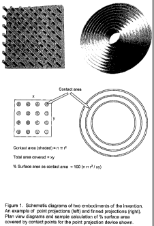
Figure 1: Schematic illustrations of two embodiments of the invention. An
example of point projection (left) and finned projections (right). A plan view
diagrams and sample calculation of % surface area covered by contact
points for the point projection are shown.
Figure 2: Diagram showing point-to-point length on contact surface and
point-to-point length on the device and sample calculation of the later
expressed as a percentage of the former.
Figure 3: Multiple point-projectile surface embodiment.
Figure 4: Concentric-finned projection embodiment with hemispherical
central section.
Figure 5: Example of tubular device with concentric fin elements for
circumferential attachment to limbs or bones
DETAILED DESCRIPTION OF THE INVENTION
EXAMPLES
Example 1: Device for the application of negative pressure to a tissue
surface
A heat-curable silicone elastomer was moulded in a concentric-finned
geometry using a collapsible funnel (Normann, Copenhagen) in the
compact position as a mould. A-central aperture was made in the device
and a luer fitting was inserted for tubing attachment. The resulting device
is shown in Figure 5.
Example 2:. Comparison of the device of Example 1 with a traditional
suction cup geometry for the application of negative pressure to an intact
human skin surface
9
CA 02713895 2010-07-30
WO 2009/103975 PCT/GB2009/000452
The device prepared in Example 1 was coupled to an intermittent (1 minute
ON, 30 minutes OFF) vacuum source running at -200 mmHg relative to
ambient atmospheric pressure. The vacuum source had a one-way valve,
fitted to its exhaust to minimise vacuum loss during the OFF phase.
During. the ON phase, the device was placed gently against the skin of the
abdomen. The device corrugated under the force of atmospheric pressure
but the outermost sealing fin remained integral to the skin. The device,
even in the absence of any adhesive, remained in place during repeated
ON-OFF cycles. The device was left in place over 48 hours, including
during normal tasks such as driving, removing and putting on clothing and
sitting and standing.
For comparison, a soft silicone-based suction cup of traditional geometry
(Cetacean Research Technology, Seattle, USA) was fitted with a luer fitting
in a central position. This device was coupled to the vacuum source and
put in tissue contact, in an identical manner as above. The device
remained in place during the initial ON phase but detached within seconds
of the commencement of the first OFF phase.
The device of the invention remained in place for the period of the
evaluation, in contrast to the traditional control, because it was able to
maintain a sufficiently air-tight seal at its perimeter.. It was able to
achieve
this because movements of the tissue surface (extensive, compressive and
geometrical distortion) could be accommodated by flexing of the device in
a manner that generated negligible force at the device perimeter seal. This
is in contrast to a traditional cup geometry, where the perimeter seal can
easily be mechanically displaced during movement of the tissue surface
(particularly extension).
Example 3: Device for the application of negative pressure to a tissue
surface
A heat-curable silicone elastomer was moulded in a hemispherical
geometry using- a double-walled mould. The set hemisphere was
transferred to sit in the centre of a collapsible funnel (Normann,
Copenhagen) in the compact position and additional heat-curable silicone
CA 02713895 2010-07-30
WO 2009/103975 PCT/GB2009/000452
elastomer was moulded. around it. The resulting device had a central
aperture made and a pressure-crackable valve (Minivalve International
B.V.) was inserted into it. The resulting device is shown in Figure 4.
Example 4: Comparison of the device of Example 3 with a traditional
suction cup geometry for the application of negative pressure to an intact
human skin surface
The device prepared in Example 3 was placed in contact with human
abdominal tissue. The hemispherical dome section of the device was
temporarily connected to a vacuum of -200 mmHg relative to ambient
atmospheric pressure. When the dressing was fully compressed, the
vacuum source was_decoupled. The pressure-crackable valve maintained
the level of vacuum initially obtained. The device remained in place for 3
hours before becoming detached when the contained vacuum decayed to
a level unable to maintain the perimeter seal.
For comparison, a soft silicone-based suction cup of traditional geometry
(Cetacean Research Technology, Seattle, USA) was fitted with a pressure-
crackable valve in a central position. This device was coupled to the
vacuum source and put in tissue contact in an identical manner as above.
The device remained attached for under 30 seconds.
The device of the invention remained in place for 3 hours, in contrast to the
traditional control, because it was able to maintain a sufficiently air-tight
seal at its perimeter, as discussed in Example 2.
Example 5: Device for attachment to articulating tissue
A heat-curable silicone elastomer was moulded in multiple point-projectile
geometry. The points were positioned in a regularly repeating square unit-
cell geometry. A silicone elastomeric pressure 'sensitive adhesive was
coated into the tips of the projections. The resulting device is shown in
Figure 3.
11