Note: Descriptions are shown in the official language in which they were submitted.
CA 02713985 2010-08-03
WO 2009/101434 PCT/GB2009/050129
- 1 -
Catalytic Reaction Module
This invention relates to a catalytic reaction module with channels for
performing an
endothermic chemical reaction such as steam reforming, in which the heat is
provided by a
combustion reaction in adjacent channels, and to a method for performing an
endothermic
chemical reaction with such a module, and to the control of such a module.
A plant and process are described in WO 2005/102511 (GTL Microsystems AG) in
which methane is reacted with steam, to generate carbon monoxide and hydrogen
in a first
catalytic reactor; the resulting gas mixture is then used to perform Fischer-
Tropsch synthesis
in a second catalytic reactor. The reforming reaction is typically carried out
at a temperature
of about 800 C, and the heat required may be provided by catalytic combustion
in channels
adjacent to those in which reforming is carried out, the combustion channels
containing a
catalyst which may comprise palladium or palladium/platinum on an alumina
support in the
form of a thin coating on a metallic substrate. An inflammable gas mixture
such as a mixture
of methane and air is supplied to the combustion channels. Combustion occurs
at the
surface of the catalyst without a flame. However, it has been found that the
combustion
reaction tends to occur most vigorously near the start of the combustion
channel, which can
lead to an unsuitable temperature distribution along the channel; although
this problem may
be overcome by staging fuel injection along the combustion channel, an
alternative solution
would be desirable.
According to the present invention there is provided a catalytic reaction
module for
performing an endothermic reaction, the module comprising a plurality of
separate reactor
blocks, each reactor block defining a multiplicity of first and second flow
channels arranged
alternately within the block to ensure thermal contact between the first and
second flow
channels, the reactor blocks being arranged and connected for series flow of a
gas mixture to
undergo the endothermic reaction in the first flow channels and also for flow
of a combustible
gas mixture in the second flow channels, such that the endothermic reaction
mixture flows in
series through the reactor blocks.
The reactor blocks are referred to as being separate in the sense that they
have
distinct and separate inlets and outlets for the gas mixtures. The reactor
blocks may also be
physically separate, that is to say spaced apart from each other; or they may
be joined
together for example as a stack.
Preferably the module is arranged such that the combustible gas mixture
provided to
a reactor block is at an elevated temperature below its auto-ignition
temperature, the
temperature being raised at least in part as a result of combustion of
combustible gas mixture
in one or more of the reactor blocks. Indeed preferably the combustible gas
mixture provided
CA 02713985 2010-08-03
WO 2009/101434 PCT/GB2009/050129
- 2 -
to each reactor block in the module is at such an elevated temperature. For at
least some of
the blocks the temperature may be raised by heat exchange with gases emerging
from the
second gas flow channels of one or more of the reactor blocks. In one
preferred embodiment
the combustible gas mixture is arranged to flow in series through the reactor
blocks in the
same order as the endothermic gas mixture. In this case the combustible gas
mixture
provided to a second or subsequent reactor block is at an elevated temperature
as a result of
having at least partly undergone combustion in the preceding reactor block of
the series.
The combustible gas mixture comprises a fuel (such as methane) and a source of
oxygen (such as air). Preferably between successive reactor blocks means are
provided to
treat the outflowing gas mixture that has undergone combustion, for example to
change its
temperature, or to introduce and mix in additional fuel. It may also be
desirable between
successive reactor blocks to provide means to introduce additional air into
the outflowing gas
mixture that results from combustion. By staging the provision of fuel between
different
reactor blocks and by staging the introduction of air, greater control over
the temperature
distribution can be achieved. For example, if there are two reactor blocks in
series, the
proportion of the fuel provided at the first stage is preferably between 50%
and 70% of the
total required fuel, the remainder being provided for the second stage.
The invention also provides a method of performing an endothermic reaction
wherein
the heat required for the endothermic reaction is provided by a combustion
reaction in an
adjacent channel to the endothermic reaction, wherein the endothermic reaction
is carried out
in a plurality of successive stages. The endothermic reaction may be steam
methane
reforming, and in this case preferably the temperature in the endothermic
reaction channels
increases through the first stage to between 675 C and 700 C, preferably to
about 690 C;
and increases through the second stage to between 730 C and 800 C, preferably
to about
760 C. In a preferred embodiment the combustion reaction is also carried out
in at least two
successive stages, with treatment of the combustion gas mixture emerging from
one stage
before it is introduced to the next stage.
The treatment of the combustion gas mixture between successive stages
preferably
comprises changing its temperature and adding additional fuel. By lowering the
gas
temperature before adding additional fuel, auto-ignition can be avoided.
By performing the combustion process in a number of stages, using separate
reactor
blocks, the benefits of staged fuel injection are obtained - for example a
more uniform
temperature distribution along the reactor module - while avoiding potential
problems. In
particular this makes it possible to cool the combustion gas mixture between
successive
stages, before introducing additional fuel, which can ensure that auto-
ignition does not occur.
CA 02713985 2010-08-03
WO 2009/101434 PCT/GB2009/050129
- 3 -
The treatment of the combustion gas mixture between successive reactor blocks
takes place
within the module, but not within the reactor blocks.
Preferably the first flow channels and the second flow channels extend in
parallel
directions, within a reactor block, and the combustible gas mixture and the
endothermic
reaction mixture flow in the same direction (co-flow). Preferably the flow
channels are of
length at least 300 mm, more preferably at least 500 mm, but preferably no
longer than 1000
mm. A preferred length is between 500 mm and 700 mm, for example 600 mm. It
has been
found that co-flow operation gives better temperature control, and less risk
of hot-spots.
In the preferred embodiment each first flow channel (the channels for the
endothermic reaction) and each second flow channel (the channels for the
combustion
reaction) contains a removable catalyst structure to catalyse the respective
reaction, each
catalyst structure preferably comprising a metal substrate, and incorporating
an appropriate
catalytic material. Preferably each such catalyst structure is shaped so as to
subdivide the
flow channel into a multiplicity of parallel flow sub-channels. Preferably
each catalyst
structure includes a ceramic support material on the metal substrate, which
provides a
support for the catalyst.
The metal substrate provides strength to the catalyst structure and enhances
thermal
transfer by conduction. Preferably the metal substrate is of a steel alloy
that forms an
adherent surface coating of aluminium oxide when heated, for example a
ferritic steel alloy
that incorporates aluminium (eg Fecralloy (TM)). The substrate may be a foil,
a wire mesh or
a felt sheet, which may be corrugated, dimpled or pleated; the preferred
substrate is a thin
metal foil for example of thickness less than 100 m, which is corrugated to
define the
longitudinal sub-channels.
Each reactor block may comprise a stack of plates. For example, the first and
second flow channels may be defined by grooves in respective plates, the
plates being
stacked and then bonded together. Alternatively the flow channels may be
defined by thin
metal sheets that are castellated and stacked alternately with flat sheets;
the edges of the
flow channels may be defined by sealing strips. To ensure the required good
thermal contact
both the first and the second gas flow channels may be between 10 mm and 2 mm
high (in
cross-section); and each channel may be of width between about 3 mm and 25 mm.
The
stack of plates forming the reactor block is bonded together for example by
diffusion bonding,
brazing, or hot isostatic pressing.
Preferably a flame arrestor is provided at the inlet to each flow channel for
combustion to ensure a flame cannot propagate back into the combustible gas
mixture being
fed to the combustion channel. This may be within an inlet part of each
combustion channel,
CA 02713985 2010-08-03
WO 2009/101434 PCT/GB2009/050129
- 4 -
for example in the form of a non-catalytic insert that subdivides a portion of
the combustion
channel adjacent to the inlet into a multiplicity of narrow flow paths which
are no wider than
the maximum gap size for preventing flame propagation. For example such a non-
catalytic
insert may be a longitudinally-corrugated foil or a plurality of
longitudinally-corrugated foils in
a stack. Alternatively or additionally, where the combustible gas is supplied
through a header,
then such a flame arrestor may be provided within the header.
The present invention also provides a method of performing an endothermic
reaction,
such as steam reforming, using such a reaction module. By combining air with
the outflowing
gas mixture that results from combustion, before adding additional fuel, the
temperature of
the combustible mixture can be held below the auto-ignition temperature, so
ensuring that
combustion occurs as a heterogeneous reaction at the surface of the catalyst
structure
(rather than occurring in the gas phase).
Performing steam methane reforming in this way enables operation to be carried
out
at a high space velocity within each block, for example between 10 000 and
60,000 /hr, while
attaining more than 90% of equilibrium conversion. Similarly the combustion
reaction is
preferably carried out at a space velocity between 20 000 and 70,000 /hr. The
space velocity,
in this document, means the volume of gas supplied to a reactor per hour,
measured at
standard temperature and pressure (0 C and 1 atmosphere), as a multiple of the
free volume
of the corresponding reactor channels.
The invention also provides a method of controlling combustion; and it
provides a
method of minimising thermal stresses in a compact catalytic reactor.
The invention will now be further and more particularly described, by way of
example
only, and with reference to the accompanying drawings, in which:
Figure 1 shows a diagrammatic side view of a reaction module of the invention;
Figure 2 shows graphically the variation of temperature through the reactor
module of figure
1, and the corresponding variation of conversion in the steam methane
reaction;
Figure 3 shows a system whereby a steam methane mixture is supplied to the
module of
figure 1;
Figure 4 shows a system that incorporates a module of figure 1; and
Figure 5 shows a flow diagram of an alternative reaction module of the
invention.
The steam reforming reaction of methane is brought about by mixing steam and
methane, and contacting the mixture with a suitable catalyst at an elevated
temperature so
the steam and methane react to form carbon monoxide and hydrogen (which may be
referred
to as synthesis gas or syngas). The steam reforming reaction is endothermic,
and the heat is
provided by catalytic combustion, for example of methane mixed with air. The
combustion
CA 02713985 2010-08-03
WO 2009/101434 PCT/GB2009/050129
- 5 -
takes place over a combustion catalyst within adjacent flow channels within a
reforming
reactor. Preferably the steam/methane mixture is preheated, for example to
over 600 C,
before being introduced into the reactor. The temperature in the reformer
reactor therefore
typically increases from about 600 C at the inlet to about 750-800 C at the
outlet.
The total quantity of fuel (e.g. methane) that is required is that needed to
provide the
heat for the endothermic reaction, and for the temperature increase of the
gases (sensible
heat), and for any heat loss to the environment; the quantity of air required
is up to 10% more
than that needed to react with that amount of fuel.
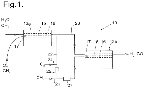
Referring now to figure 1 there is shown a reaction module 10 suitable for use
as a
steam reforming reactor. The reaction module 10 consists of two reactor blocks
12a and 12b
each of which consists of a stack of plates that are rectangular in plan view,
each plate being
of corrosion resistant high-temperature alloy. Flat plates are arranged
alternately with
castellated plates so as to define straight-through channels between opposite
ends of the
stack, each channel having an active part of length 600 mm. By way of
illustration, the height
of the castellations (typically in the range 2-10 mm) might be 3 mm in a first
example, or might
be 10 mm in a second example, while the wavelength of the castellations might
be such that
successive ligaments are 20 mm apart in the first example or might be 3 mm
apart in the
second example. All the channels extend parallel to each other, there being
headers so that
a steam/methane mixture can be provided to a first set of channels 15 and an
air/methane
mixture provided to a second set of channels 16, the first and the second
channels alternating
in the stack (the channels 15 and 16 being represented diagrammatically), such
that the top
and bottom channels in the stack are both combustion channels 16. Appropriate
catalysts for
the respective reactions are provided on corrugated foils (not shown) in the
active parts of the
channels 15 and 16, so that the void fraction is about 0.9. A flame arrestor
17 is provided at
the inlet of each of the combustion channels 16.
By way of example there may be over fifty such castellated plates in each
stack.
The steam/methane mixture flows through the reactor blocks 12a and 12b in
series,
there being a duct 20 connecting the outlet from the channels 15 of the first
reactor block 12a
to the inlet of the channels 15 of the second reactor block 12b. Similarly the
combustion
mixture also flows through the reactor blocks 12a and 12b in series, there
being a duct 22
connecting the outlet from the channels 16 of the first reactor block 12a to
the inlet of the
channels 16 of the second reactor block 12b. The duct 22 includes an inlet 24
for additional
air, followed by a static mixer 25, and then an inlet 26 for additional fuel,
followed by another
static mixer 27.
CA 02713985 2010-08-03
WO 2009/101434 PCT/GB2009/050129
- 6 -
In use of the reaction module 10, the steam/methane mixture is preheated to
620 C,
and supplied to the reaction module 10 to flow through the reactor blocks 12a
and 12b. A
mixture of 80% of the required air and 60% of the required methane (as fuel)
is preheated to
550 C, which is below the auto-ignition temperature for this composition, and
is supplied to
the first reactor block 1 2a. In both cases the preheating may be carried out
by heat exchange
with exhaust gases that have undergone combustion within the module 10. The
temperature
rises as a result of combustion at the catalyst, and the gases that result
from this combustion
emerge at a temperature of about 700 C. They are mixed with the remaining 20%
of the
required air (by the inlet 24 and the static mixer 25), and then with the
remaining 40% of the
required methane (by the inlet 26 and the static mixer 27), so that the gas
mixture supplied to
the combustion channels 16 of the second reactor block 12b is at about 600 C,
which is
again below the auto-ignition temperature for this mixture (which contains
water vapour and
carbon dioxide as a consequence of the first stage combustion). By adjusting
the
temperature of the additional air supplied at the inlet 24, the temperature of
the resulting
mixture can be controlled to be below the auto-ignition temperature.
By way of example the gas flow rates may be such that the space velocity is
preferably between 14000 and 20000 /hr and possibly more particularly between
15000 and
18000 /hr for the steam methane reforming channels (considering the reaction
module 10 as
a whole), and is preferably between 19000 and 23000 /hr for the combustion
channels
(considering the reaction module 10 as a whole).
Referring now to figure 2, this shows graphically the variations in
temperature T along
the length L of the combustion channels 16 (marked A), and that along the
reforming
channels 15 (marked B). The portion of the graph between L = 0 and L = 0.6 m
corresponds
to the first reactor block 12a, while the portion of the graph between L = 0.6
m and L = 1.2 m
corresponds to the second reactor block 12b. It will be noted that the
temperature T in a
reforming channel 15, once combustion has commenced, is always lower than the
temperature T in the adjacent combustion channel 16. The combustion gas
temperature
undergoes a downward step change as a result of the added air (from inlet 24)
between the
first reactor block 12a and the second reactor block 12b (at position L = 0.6
m). The variation
of conversion of methane, C, in the steam reforming reaction with length L is
shown by the
graph marked P. The conversion increases continuously through the reaction
module 10 and
reaches a value of about 80%, which is close to the equilibrium conversion
under the reaction
conditions.
It will be understood that adjusting the space velocities in the combustion
channels
and in the reforming channels, and adjusting the proportion of fuel and of air
provided for
combustion to each reactor block, ensures that a satisfactory temperature
distribution is
achieved throughout the reactor blocks, and that thermal stresses within each
reactor block
CA 02713985 2010-08-03
WO 2009/101434 PCT/GB2009/050129
- 7 -
are minimised. This ensures that the reactor module operates within safe
margins, without
risk of damage to the reactor blocks. It will also be appreciated that the
variations in
temperature and conversion shown in figure 2 are by way of example only, and
that the
temperature distribution and consequently the conversion will be slightly
different for example
if the combustion catalysts are altered or if the ratio of fuel to air is
altered.
It will be appreciated that the description given above is by way of example
only and
that many changes may be made while remaining within the scope of the present
invention.
For example the dimensions of the channels 15 and 16 and of the reactor blocks
12 may
differ from those indicated above. The proportions of air and methane supplied
to the first
reactor block 12a may differ from the proportions mentioned above. The
proportion of fuel
provided initially may be between 50% and 65%, more preferably 55% with the
remaining
35% to 50%, preferably 45%, being provided between the blocks 12a and 12b. For
example
100% of the required air and 65% of the required fuel might be provided
initially; and the
remaining 35% of the fuel provided between the blocks 12a and 12b, although in
that case it
may be desirable to provide a heat exchanger (not shown) to cool the out-
flowing gases to
ensure the temperature is below the auto-ignition temperature. In every case
the additional
fuel is preferably added to a gas mixture that is below the auto-ignition
temperature for the
gas mixture under the prevalent conditions of gas composition and pressure.
Where only
part of the air is provided initially, as described above, this proportion is
preferably at least
50%, and preferably no greater than 90%, more preferably between 75% and 85%,
and most
preferably 80% as in the example above.
It should be understood that the catalyst-carrying foils in the channels 15
and 16
preferably extend the entire length of the respective channels, apart from the
initial part of the
combustion channel 16 occupied by the flame arrestor 17. In a modification, no
reforming
catalyst is provided in an initial portion of each reforming channel 15, this
initial non-catalytic
portion being longer than the length of the flame arrestor 17, so that the gas
mixture that is to
undergo reforming is preheated before it reaches the reforming catalyst.
It should be appreciated that where the fuel gas consists of or contains a
significant
concentration (say > 5%) of species such as H2 and CO that have rapid
combustion kinetics
relative to methane, more than two reactor blocks and inter-stage mixing
positions may be
employed in order to control the temperature profile in the reactor module and
prevent hot
spots and adverse thermal gradients being generated.
The ability to modulate the proportions of fuel and air fed to each stage can
also be
used to compensate for reductions in catalyst activity over time. A further
refinement with this
arrangement is the ability to recycle some of the produced syngas to the fuel
mixing stages to
CA 02713985 2010-08-03
WO 2009/101434 PCT/GB2009/050129
- 8 -
maintain the temperature profile in the reactor module as the combustion
catalyst de-
activates over time.
As will be appreciated, steam methane reforming may form part of a process for
converting methane to longer-chain hydrocarbons, the synthesis gas produced by
reforming
then being subjected to Fischer-Tropsch synthesis. Alternatively, the
synthesis gas may be
subjected to a catalytic process to form methanol. The steam methane reforming
in any such
plant may be carried out using one or more reaction modules 10 as described
above. A
preferred plant incorporates several such reaction modules arranged in
parallel, so that the
plant capacity can be adjusted by changing the number of reaction modules that
are utilised.
In the reaction module 10 shown in Figure 1, and considering only the
combustion
channels 16, a platinum-palladium catalyst may be provided in both reactor
blocks 12a and
12b. Alternatively the catalyst may be different in the two reactor blocks 12a
and 12b. For
example the catalyst in the first reactor block 12a may be platinum-palladium,
and the catalyst
in the second reactor block 12b instead might be platinum only. It will be
appreciated that the
oxygen partial pressure within the second reactor block 12b is less than that
in the first
reactor block 12a because of the combustion that has taken place. If a
platinum-palladium
catalyst is used in the second reactor block 12b a problem can arise, because
this low
oxygen partial pressure encourages the transformation of palladium oxide to
palladium metal,
and palladium metal is less effective as a combustion catalyst than palladium
oxide. Hence
there can be a benefit from using a platinum-only catalyst within the second
reactor block
12b, or from using a platinum-palladium mixture with a high proportion of
platinum in the
second reactor block 12b. Platinum is catalytically active in the metal form,
rather than the
oxide form, and therefore the activity of the catalyst is not adversely
affected by the low
oxygen partial pressure within the second reactor block 12b. As another
alternative a
platinum-only catalyst could be used in both reactor blocks 12a and 12b.
However, a
platinum catalyst has a lower light-off temperature than a platinum-palladium
catalyst, so it is
not as suitable for use in the first reactor block 12a, and in addition, the
oxygen partial
pressure is higher in the first reactor block 12a and therefore the platinum-
only catalyst does
not provide the benefit that it would in the second reactor block 12b.
An alternative reaction module 100 is shown in figure 5, to which reference is
now
made, components that are the same as those of the module 10 being referred to
by the
same references. The reaction module 100 consists of two reactor blocks 12a
and 12b
represented schematically, and the steam/methane mixture flows through the
reactor blocks
12a, 12b in series via the duct 20 as described above. Separate combustion
mixtures are
supplied to each of the reactor blocks 12a and 12b, and the exhaust gases
emerging from the
combustion channels 16 of both the reactor blocks 12a and 12b are provided to
a common
CA 02713985 2010-08-03
WO 2009/101434 PCT/GB2009/050129
- 9 -
exhaust vent 102 (or to two separate exhaust vents). The combustion mixture
supplied to the
second reactor block 12b is preheated to 550 C, which is below its auto-
ignition temperature,
by preheating the air and fuel in heat exchangers 104 and 105 heated by the
exhaust gases
in the vent 102, the preheated air and fuel then being mixed in a mixer 27.
(The combustion
mixture supplied to the first reactor block 12a may be preheated similarly.)
The combustion mixture supplied to the first reactor block 12a of the module
100 may
have the same composition as is supplied to the second reactor block 12b.
Hence 50% of the
total fuel requirement may be supplied to the first reactor block 12a and the
remaining 50% to
the second reactor block 12b, each block being provided with the same volume
of air.
However, it should be noted that the volume of fuel supplied to the first
reactor block 12a may
be the same as that supplied to the first reactor block of the module 10.
Consequently the
overall amount of fuel supplied to the module 100 may be greater than the
amount of fuel
supplied to the module 10.
Alternatively a somewhat higher proportion of the total fuel requirement may
be
provided to the first reactor block 12a, for example 55%, and the remaining
45% of the total
being provided to the second reactor block 12b. By venting at least part of
the exhaust gases
from the first stage combustion reaction, the percentage of the product gases
water vapour
and carbon dioxide in the channels of the second reactor block 12b is reduced
compared to
that in figure 1. This, in turn, contributes to an increased partial oxygen
pressure in the
second reactor block 12b. Consequently a palladium/platinum catalyst is
suitable for use in
the combustion channels 16 of both the reactor blocks 12a and 12b. The
temperature
distribution through the module 100 is substantially the same as that
described in relation to
figure 2 in the module 10, and the overall conversion achieved in the steam
methane
reforming channels is substantially the same.
Referring now to figure 3 this shows a flow diagram of a system 30 for
supplying a
steam methane mixture to a reforming module 10 as described above, or to a
reforming
module 100 as described above, as part of a plant for processing natural gas.
The processing
plant, in this example, converts natural gas to longer chain hydrocarbon
products. The
natural gas is initially conditioned to remove impurities such as mercury or
sulphur and so
provide a feed stream of clean natural gas, typically about 90% of methane
with small
percentages of other alkanes. This is used to generate synthesis gas, by steam
methane
reforming. The synthesis gas is subjected to Fischer-Tropsch synthesis to
generate the
longer chain hydrocarbons, leaving a residual tail gas; this tail gas may
consist primarily of
short chain alkanes, carbon monoxide, carbon dioxide, water vapour, and
hydrogen.
The system 30 is intended for use in such a processing plant, and in this
example is
provided with three input streams: the feed stream 31 of clean natural gas, a
supply of steam
CA 02713985 2010-08-03
WO 2009/101434 PCT/GB2009/050129
- 10 -
32, and tail gas 33 recycled from the Fischer-Tropsch synthesis plant. The
system 30
generates a mixture containing natural gas and steam, and subjects this to pre-
reforming, for
example using a nickel catalyst, in a pre-reformer 35, to convert any C2+
hydrocarbons
(ethane, propane, etc.) to methane, carbon monoxide and hydrogen. The flows
are ideally
such that the steam:methane molar ratio after pre-reforming is between 1.4 and
1.6 to 1. The
resulting gas mixture 36 consists primarily of methane and steam, and is
supplied to one or
more reforming reactor modules 10 as described above.
The system 30 includes a control system 38 to control the ratio of steam to
carbon
(whether in methane or another alkane) that is supplied to the pre-reformer
35. During
normal operation the steam:carbon ratio will be about 1.4 to 1, but during
start-up a higher
proportion of steam is used to avoid coking of the catalyst in the reformer
module 10 while the
catalyst temperatures rise to their target values. Flow transmitters 40
measure the flow of the
input streams 31, 32 and 33, and supply data to a fuel flow controller 42. The
fuel flow
controller 42 operates a control valve 44 to adjust the flow rate of the steam
and so to ensure
the required steam to carbon ratio. Signals from the flow transmitter 40
measuring the feed
gas flow 31 are also transmitted to a flow controller 46 that operates a vent
valve 48 to divert
any peaks in the feed gas flow rate out of the system 30, for example to a
flare (not shown).
A heat exchanger 50 is provided to heat the recycled tail gas stream 33 to the
same
temperature as the steam 32 and feed gas 31, which in this plant have been
previously
heated to an elevated temperature. The gas streams 31, 32 and 33 are then
mixed, and the
resulting gas mixture is then further heated by a pre-heater 52 to the
required input
temperature for the pre-reformer 35, typically about 425 C.
The flow rates of the feed gas 31 and of the tail gas 33 as measured by the
corresponding flow transmitters 40, but allowing for the effect of the vent
valve 48, are
calculated and transmitted at 54 for controlling the steam methane reforming
module 10 (as
described below).
The reaction in the pre-reformer 35 may be catalysed by a pre-reduced and
stabilised
nickel based catalyst. Because the tail gas 33 is included within the gas
mixture, the gas
mixture contains carbon monoxide and carbon dioxide, and consequently the
reaction in the
pre-reformer is slightly exothermic, and the temperature of the resulting
output stream 36 is
about 540 C.
Controlling the temperature and composition of the mixture fed to the pre-
reformer 35
is necessary in order to protect the catalysts in the pre-reformer 35 and the
reforming reactor
module 10. For example, steam should not be introduced if condensing
conditions are
present, for example if the temperature within the pre-reformer 35 is less
than 180 C. Steam
CA 02713985 2010-08-03
WO 2009/101434 PCT/GB2009/050129
- 11 -
also must not be allowed to flow through the pre-reformer 35 on its own for
longer than 15
minutes, or the catalyst may start to undergo an irreversible oxidation
reaction. To prevent
oxidation of the catalyst, the steam 32 should be mixed with at least a small
proportion of
hydrogen or natural gas, for example 10 mole%. The pre-reformer 35 can pass
natural gas
at up to 200 C without detriment, but the catalyst will be destroyed by coking
within about 20
s if natural gas is passed over the catalyst at above 250 C. It is therefore
important to shut
off the natural gas feed stream 31 if the steam supply 32 ceases, and the tail
gas stream 33
must also be shut off. The pre-reformer 35 must not be de-pressurised faster
than 1 bar/min
to avoid damaging the catalyst, and should also not be heated or cooled faster
than 1 C/min.
Referring now to figure 4 there is shown a flow diagram of a system 60 to
control
operation of a steam reforming module 10 as shown in figure 1. The gas
supplies in this case
are: desulphurised natural gas 61 as fuel; the gas mixture 36 from the pre-
reformer 35; and
blown air 62. The gas mixture 36, which consists primarily of steam and
methane, is
subjected to a control loop comprising a pressure transmitter 64 that provides
data about the
pressure of the gas mixture 36 to a pressure controller 65; the pressure
controller 65 can
adjust the flow rate using a control valve 66 and can open a vent valve 67 to
divert the gas
mixture to a flare if the pressure of the gas mixture 36 exceeds a
predetermined safe
threshold pressure for the reactor module 10. The gas mixture 36 is then fed
through a pre-
heater 68 into the reactor module 10.
The reactor module 10 is also supplied with a mixture of blown air 62 and
desulphurised natural gas 61 for the combustion reactions. The blown air 62 is
first heated
through a pre-heater 604, and then its temperature is measured by a
temperature sensor
605. The flow rate of air supplied to the module 10 is adjusted by a valve 606
in response to
control signals from a controller 70. The controller 70 receives data from
both the
temperature sensor 605 and also an oxygen sensor 607 at the outlet for the
combustion
gases from the second module 12b.
The blown air 62, after passing through the valve 606, is separated into a
first air flow
supplied through a heat exchanger 610 to a static mixer 618 (to be mixed with
fuel gas) at the
inlet for the first reactor module 1 2a, and a second air flow supplied
through a heat exchanger
611 to the inlet 24 of the static mixer 25 at the outlet from the first
reactor module 12a. The
ratio of the first and second air flows is controlled by a valve 608 in the
second air flow. This
valve 608 is controlled by a controller 72 that receives input signals from a
temperature
sensor 609 at the outlet from the static mixer 25, and a flow sensor 74 at the
inlet to the valve
608. The heat exchangers 610 and 611 can be controlled separately, the heat
exchanger
610 heating the air to a temperature of around 500 C, whilst the second stage
heater 611
heats the air to a temperature in the region of 300 C.
CA 02713985 2010-08-03
WO 2009/101434 PCT/GB2009/050129
- 12 -
The desulphurised gas 61 that is the fuel for combustion is controlled in a
similar
manner to the blown air 62, although as explained above the mixture supplied
to the first
reactor block 12a may be 80% of the required air and 55% or 60% of the
required fuel. The
rest of the required air and the rest of the required fuel are introduced
through the static
mixers 25 and 27 between the first reactor block 12a and the second reactor
block 12b. The
fuel flow 61 is split into two flows: a first flow via a control valve 614 and
a heat exchanger
616 to the static mixer 618 at the inlet to the first reactor block 12a, and a
second flow via a
control valve 615 and a heat exchanger 617 to the inlet 26 of the static mixer
27. The first flow
is heated to about 500 C or 550 C by the heat exchanger 616, whereas the
second flow is
heated to about 300 C by the heat exchanger 617.
The overall control of the system 60 is provided by a controller 612. The
controller
612 receives the signals 54 indicating the flows of natural gas 31 and tail
gas 33 (see figure
3) from which it can deduce the flow of methane to be reformed. The controller
612 also
receives data from a temperature sensor 613 at the outlet of the second
reactor block 12b. It
also receives data from the controller 70 about the flow of blown air 62. The
controller 612
controls the flow of fuel through the valves 614 and 615 by providing signals
to respective
valve controllers 76 and 78 that also receive data on the flow rate from flow
sensors 77 and
79. The controller 612 also controls the flow rate of blown air 62 through the
valve 606, by
providing control signals to the controller 70.
Thus in operation of the system 60, the air supply to the module 10, that is
to say the
flow of the blown air 62, is controlled by the controller 612 and the
controller 70 in accordance
with the quantity of methane to be reformed. If the oxygen level sensed by the
sensor 607 at
the outlet from the module 10 decreases, then the valve 606 is adjusted to
increase the flow
of blown air 62 to the module 10. If the oxygen level increases, then the flow
of blown air 62
to the module 10 is decreased, and the flow rate of the fuel 61 is also
reduced in proportion.
The flow rate of the fuel 61 is also controlled in accordance with the
quantity of
methane to be reformed. In addition, if the temperature sensed by the sensor
613 at the outlet
from the module 10 becomes excessively high, then the flow rate of the fuel 61
to both the
reactor blocks 12a and 12b would be reduced. On the other hand, if the
temperature sensed
by the sensor 609 at the outlet from the static mixer 25 rises, the air supply
to the inlet 24 of
the static mixer 25 is increased (or alternatively the heat exchanger 611
might be adjusted to
achieve a lower temperature). This ensures that the gas mixture in the mixer
27 is below its
auto-ignition temperature.
A system to control operation of a steam reforming module 100 as shown in
figure 5
may be similar to the system 60 described above with the exception that the
output of the
combustion channels from the first reactor block 12a is vented, and a new
mixture of air and
CA 02713985 2010-08-03
WO 2009/101434 PCT/GB2009/050129
- 13 -
fuel is supplied. There is therefore no need for the static mixer 25, only the
mixer 27. In the
module 100 the temperatures and quantities of gas input into the two stages
can be
independently controlled, and the temperature of the air and fuel for the
second reactor block
12b, controlled by heat exchangers 611, 617 (which correspond to the heat
exchangers 105
and 104 of figure 5) respectively, can be up to 500 C or 550 C (rather than
300 C as
described above).
The control system 30 is described as receiving two sources of hydrocarbons:
natural
gas 31 and a tail gas 33. It will be appreciated that this is by way of
example only, as the
requirement is only that there must be at least one gas supply that contains
hydrocarbons,
typically a natural gas supply. If a second source of gaseous hydrocarbons is
available, then
this may also be supplied in an analogous way to the tail gas 33. For example,
where such a
pre-reformer 35 and associated control system 30 are provided in the context
of a different
processing plant, for example a processing plant for producing methanol rather
than for
producing longer chain hydrocarbons, then there may be only a single such gas
supply to the
pre-reformer 35, or there may also be a tail gas of a different composition
from that described
above.