Note: Descriptions are shown in the official language in which they were submitted.
CA 02714017 2013-09-19
ALTERNATIVE PATH COOLING OF
A HIGH TEMPERATURE FUEL CELL
Background
A fuel cell operates by creating an electrochemical reaction between incoming
fuel and oxidizer streams to create electricity. Many fuel cells, such as
solid oxide fuel
cells (SOFC), operate at high temperatures. Waste heat created by the
electrochemical
reaction within a fuel cell must be removed to control the temperature of the
fuel cell to
prevent failure of the cell A typical thermal management system includes
circulating
excess reactant, beyond what is needed for the electrochemical reaction,
through the fuel
cell to absorb heat. However, in certain applications, such as an airborne
application in
which a fuel cell is utilized on an aircraft, weight is a primary
consideration. Storing the
excess reactant required to maintain the temperature of the fuel cell can be
weight
prohibitive.
Gases exiting the fuel cell can be recirculated back to an incoming reactant
stream
for cooling purposes. However, doing so requires an additional cooling
subsystem to
cool the recycled flow due to the heat absorbed from the fuel cell. The
additional cooling
subsystem results in a more complex control system, additional vehicle thermal
load, and
an increased weight of the overall system. Another conventional thermal
management
system includes a separate closed system cooling loop for circulating a stored
coolant
through the fuel cell and through a cooling subsystem. Similar to the other
thermal
management systems described above, a separate closed system cooling loop adds
additional weight and adds complexity with additional pumps, coolant, lines,
and power
consumption requirements.
It is with respect to these considerations and others that the disclosure made
herein is presented.
Summary
It should be appreciated that this Summary is provided to introduce a
selection of
concepts in a simplified form that are further described below in the Detailed
Description.
This Summary is not intended to be used to limit the scope of the claimed
subject matter
1
CA 02714017 2014-12-11
Systems and methods described herein provide for the cooling of a fuel cell
using an
ambient coolant, such as air or water depending on the application.
The disclosure describes a method of cooling a fuel cell. The method involves
capturing a non-reactive airflow from an ambient environment. The method also
involves
causing the entire non-reactive airflow to enter a heat exchanger in the fuel
cell to cause
heat from the fuel cell to be absorbed by the non-reactive airflow, whereby
the non-
reactive airflow becomes heated non-reactive airflow. The method further
involves
causing at least some of the heated non-reactive airflow to drive a turbine.
The method
also involves driving a compressor with power from the turbine and causing the
compressor to compress non-reactive airflow from a source to create the flow
of non-
reactive airflow. The method further involves causing at least some of the
heated non-
reactive airflow to commingle with the flow of non-reactive airflow entering
the heat
exchanger to preheat the flow of non-reactive airflow to a temperature lower
than a
temperature of the fuel cell before the non-reactive airflow enters the heat
exchanger.
The disclosure also describes a fuel cell cooling apparatus for cooling a fuel
cell
having an internal heat exchanger. The apparatus includes provisions for
capturing a non-
reactive airflow from an ambient environment and a compressor for compressing
the
entire captured non-reactive airflow to produce a pressurized flow of non-
reactive
airflow. The apparatus further includes the heat exchanger being operable to
receive the
pressurized flow of non-reactive airflow and to cause heat from the fuel cell
to be
absorbed by the non-reactive airflow whereby the non-reactive airflow becomes
heated
non-reactive airflow. The apparatus also includes a turbine operably
configured to receive
the flow of heated non-reactant airflow for driving the turbine and wherein
the
compressor is driven by power provided by the turbine. The apparatus further
includes
provisions for causing at least some of the heated non-reactive airflow to
commingle with
the pressurized flow of non-reactive airflow entering the heat exchanger to
preheat the
pressurized non-reactive airflow to a temperature lower than a temperature of
the fuel cell
before the non-reactive airflow enters the heat exchanger.
2
CA 02714017 2015-08-04
The disclosure also describes a system for thermal management of a fuel cell.
The system
includes a first reactant supply mechanism closed to an ambient environment
and configured to
store and supply oxygen to the fuel cell for a fuel cell reaction. The system
also includes a
second reactant supply mechanism closed to the ambient environment and
configured to store
and supply fuel to the fuel cell for the fuel cell reaction. The system
further includes a coolant
supply mechanism coupled to the ambient environment and isolated from the
first reactant
supply mechanism and from the second reactant supply mechanism including an
inlet defining a
channel through which a non-reactant ambient airflow is captured from the
ambient
environment. The coolant supply mechanism operative to provide an entire
portion of the non-
reactant ambient airflow captured through the channel from the ambient
environment to the fuel
cell. The system also includes a heat exchanger within the fuel cell
configured to receive the
entire portion of the non-reactant ambient airflow captured through the
channel from the ambient
environment from the coolant supply mechanism and to route the entire portion
of the non-
reactant ambient airflow through a portion of the fuel cell to absorb heat
from the fuel cell to
create heated coolant, and to discharge the heated coolant from the fuel cell.
The system further
includes a heat disposal mechanism configured to receive the heated coolant
discharged from the
heat exchanger and direct the heated coolant away from the fuel cell.
The disclosure also describes a system for thermal management of a fuel cell.
The system
also includes a first reactant supply mechanism closed to an ambient
environment and configured
to store and supply oxygen to the fuel cell for a fuel cell reaction. The
system also includes a
second reactant supply mechanism closed to the ambient environment and
configured to store
and supply fuel to the fuel cell for the fuel cell reaction. The system
further includes a coolant
supply mechanism coupled to the ambient environment and isolated from the
first reactant
supply mechanism and from the second reactant supply mechanism, the coolant
supply
mechanism configured to provide ram air to a heat exchanger within the fuel
cell directly from a
ram air inlet of a vehicle or from a compressor receiving the ram air from the
ram air inlet.
2a
CA 02714017 2013-09-19
Brief Description Of The Drawings
FIGURE 1 is a block diagram showing a fuel cell cooling system according to
various embodiments presented herein;
FIGURE 2 is a block diagram showing a fuel cell cooling system that utilizes a
turbine-driven compressor according to various embodiments presented herein;
FIGURE 3 is a block diagram showing a fuel cell cooling system that utilizes
recirculated coolant to increase the temperature of the ambient coolant
entering the fuel
cell according to various embodiments presented herein;
2b
CA 02714017 2010-08-04
WO 2009/129012
PCT/US2009/037340
FIGURE 4 is a schematic diagram showing the flow of coolant through a fuel
cell
cooling system to illustrate heat transfers at various stages within the
system according to various
embodiments presented herein; and
FIGURE 5 is a flow diagram illustrating a method for controlling the
temperature of a
high temperature fuel cell according to various embodiments presented herein.
Detailed Description
The following detailed description is directed to systems and methods for
controlling the
temperature of a fuel cell. As discussed briefly above, fuel cell systems
include two input flows,
a fuel and an oxidizer. Typical thermal management systems utilize excess
reactant flow and/or
separate closed system cooling loops to control the temperature of the
corresponding fuel cell.
These systems are not always optimal when the fuel cell operates in a vehicle
or platform having
stringent weight, space, and power constraints.
Throughout this disclosure, for illustrative purposes, the various embodiments
will be
described with respect to the operation of a high temperature fuel cell, such
as a SOFC, used to
create electrical power for an aircraft or aircraft subsystem. However, it
should be understood
that the disclosure provided herein is equally applicable to any type of fuel
cell used in any
application in which an ambient flow of coolant is readily available. As an
example of "coolant"
as disclosed herein, aircraft and vehicles propel themselves through the
surrounding air, creating
an ambient airflow that may be used as a coolant according to the various
embodiments
described herein. Similarly, vessels such as ships and submarines propel
themselves through the
surrounding water, creating an ambient water flow that may be used as the
coolant described
below with respect to various embodiments. Accordingly, the flow of the
"ambient coolant" and
"coolant" described herein applies to the flow of any fluid, and according to
various
embodiments, to the fluid within the environment surrounding the platform
containing the fuel
cell to be cooled. The flow of the "ambient coolant" also applies towards
stationary systems
where the coolant flow is driven into the system.
Utilizing the concepts and technologies described herein, a high temperature
fuel cell
system may be operated in a manner that allows for thermal control of the fuel
cell stack,
utilizing a coolant stream that is separate from the reactant streams flowing
into the fuel cell.
Once heated by an exchange of heat within the fuel cell, the heated coolant
may be utilized to
3
CA 02714017 2015-08-04
create additional electricity and/or drive further system components as
described below. Because
the separate coolant stream is input to the fuel cell system from the ambient
environment rather
than storage, and because the output coolant containing the waste heat from
the fuel cell may be
utilized to drive system components and create additional power, the
embodiments disclosed
herein may provide for an efficient, weight-effective thermal management
system.
In the following detailed description, references are made to the accompanying
drawings
that form a part hereof, and which are shown by way of illustration, specific
embodiments, or
examples. Referring now to the drawings, in which like numerals represent like
elements through
the several figures, thermal management of a high temperature fuel cell
cooling system will be
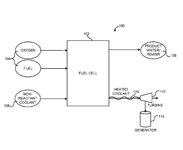
described. FIGURE 1 shows a high temperature fuel cell cooling system 100
according to one
embodiment described herein. The high temperature fuel cell cooling system 100
includes a fuel
cell 102 that is operative to create products 106, such as water and
electricity, from an
electrochemical reaction of the reactants 104, which include oxygen and a
fuel.
A non-reactant coolant 108 is routed to the fuel cell 102. According to one
embodiment,
the non-reactant coolant 108 includes ram air captured by the high temperature
fuel cell cooling
system 100 from ambient air rushing past the vehicle containing the high
temperature fuel cell
cooling system 100. A coolant supply mechanism for supplying the ram air to
the fuel cell 102
may include ducting and any other components that capture the ambient airflow
and transport it
into and through the fuel cell 102. An example of an alternative coolant
supply mechanism will
be described below with respect to FIGURE 2.
Within the fuel cell 102, the ambient air can be routed throughout the fuel
cell via ducts,
conduit, apertures, or other channels to absorb waste heat from the
electrochemical reaction
inside. In this manner, the fuel cell 102, or portions of the fuel cell that
thermally contact the
non-reactant coolant 108, operates as a heat exchanger, transferring heat from
the higher
temperature fuel cell to the lower temperature non-reactant coolant 108. The
heated coolant 110
containing the non-reactant coolant 108 saturated with waste heat is
discharged from the fuel cell
102.
The high temperature fuel cell cooling system 100 may include a heat disposal
mechanism that receives the heated coolant 110 from the fuel cell 102 and
disposes or otherwise
utilizes it. The heated coolant 110 may be utilized in any number and
combination of ways
4
CA 02714017 2010-08-04
WO 2009/129012
PCT/US2009/037340
according to various embodiments described herein. First, the heat disposal
mechanism may
simply include ducting and components for venting the heated coolant 110 to
the ambient
environment. For example, ram air that is forced through the fuel cell 102 may
be discharged to
the atmosphere.
An alternative heat disposal mechanism may include a turbine 112, as shown in
FIGURE
1. The turbine 112 may be coupled to a generator 114. In this embodiment, the
heated coolant
110 drives the turbine 112, which in turn drives the generator 114 to create
electricity. The
generator 114 can provide power to an aircraft system in addition to the power
created by the
electrochemical reaction within the fuel cell 102. Heated coolant 110 leaving
the turbine 112
may be vented to the ambient environment. The heat disposal mechanism may
additionally
include a recirculation device 302, which will be described in detail below
with respect to
FIGURE 3.
FIGURE 2 shows an alternative high temperature fuel cell cooling system 200
that
utilizes an alternative coolant supply mechanism. Specifically, the
alternative coolant supply
mechanism includes a compressor 202 for supplying the non-reactant coolant 108
to the fuel cell
102. According to this embodiment, ram air is not utilized to cool the fuel
cell 102. Rather, low
pressure, non-reactant ambient airflow is routed to the compressor 202, which
provides some
pressurization of the non-reactant coolant 108 to supply it to the fuel cell
102. As an example, in
a regenerative high altitude aircraft power system, oxygen and hydrogen are
both stored under
pressure. However, since the cooling air stream is not reactive, it would not
be necessary to
highly pressurize the stream. As a result, the compressor 202 may utilize a
single stage system
without any interstage cooling.
Further according to this embodiment, the turbine 112 of the heat disposal
mechanism
described above for managing the heated coolant 110 from the fuel cell 102 is
used to
mechanically drive the compressor 202. The compressor may also be driven by
other means
such as an alternative electrical source or from the generator (114). It
should be understood that
the turbine 112 and the generator 114 may be utilized to mechanically or
electrically drive any
number and type of desired platform components within the scope of this
disclosure, provided
that the characteristics of the heated coolant 110 allow for the desired
turbine 112 and generator
114 output.
5
CA 02714017 2010-08-04
WO 2009/129012
PCT/US2009/037340
Looking at FIGURE 3, yet another alternative high temperature fuel cell
cooling system
300 includes a recirculation device 302 to route a portion of the heated
coolant 110 back into the
non-reactant coolant 108 flowing into the fuel cell 102. The recirculation
device 302 may
include a fan or ejector that is operative to supply the heated coolant 110 to
the non-reactant
coolant 108 stream entering the fuel cell. Because of the significant
temperature differential that
may be present between the ambient coolant exiting the compressor 202 and the
fuel cell 102,
there may be a high potential for damage to the fuel cell 102 due to thermal
shock that would
occur from utilizing a non-reactant coolant 108 that is significantly cooler
than the fuel cell 102
reaction. As a result, embodiments described herein provide for the heating of
the non-reactant
coolant 108 stream to a temperature higher than the temperature of the non-
reactant coolant 108
exiting the compressor 202, but lower than that of the fuel cell 102.
According to various embodiments, heating the non-reactant coolant 108 with
the heated
coolant 110 upstream from the fuel cell 102 may occur through an actual mixing
of the two
flows or via thermal contact between the two flows without commingling the non-
reactant
coolant 108 and the heated coolant 110. To transfer heat from the heated
coolant 110 to the non-
reactant coolant 108 without commingling the two flows, a recuperator, or heat
exchanger, may
be used. An implementation utilizing a recuperator will be described with
respect to FIGURE 4.
FIGURE 4 illustrates the path of coolant flow through a high temperature fuel
cell
cooling system 400. Various heat transfers at different stages within the
system will now be
discussed using illustrative temperature values. It should be understood that
the temperature
values described are for illustration purposes only. The actual temperature
differentials between
the various stages of the high temperature fuel cell cooling system 400 will
depend on any
number of factors, including but not limited to the operating characteristics
of the fuel cell 102,
the heat capacity of the non-reactant coolant 108, the flow rates of the non-
reactant coolant 108
throughout the system, the operational specifications of the compressor 202
and the turbine 112,
and the characteristics of the recuperator 402, among others.
At stage 1, the non-reactant coolant 108 enters the compressor 202 at -51C as
an ambient
airflow from outside of an aircraft at altitude. The non-reactant coolant 108
heats as it is
pressurized by the compressor, exiting the compressor 202 at 84C at stage 2.
From stage 2, the
non-reactant coolant 108 enters the recuperator 402. As described above, the
recuperator 402 is
a heat exchanger that transfers heat from heated coolant 110 from the fuel
cell 102 to the non-
reactant coolant 108 entering the fuel cell 102 in an effort to prevent
thermal shock from
6
CA 02714017 2010-08-04
WO 2009/129012
PCT/US2009/037340
damaging the fuel cell 102 as a result of an excessive temperature
differential between the non-
reactant coolant 108 entering the fuel cell 102 and the heat within the fuel
cell 102. After
heating the non-reactant coolant 108 within the recuperator 402, the non-
reactant coolant 108
exits the recuperator 402 and enters the fuel cell 102 at 625C at stage 3.
The non-reactant coolant 108 absorbs further heat within the fuel cell 102,
becoming
heated coolant 110. The heated coolant 110 exits the fuel cell 102 and re-
enters the recuperator
402 at 800C at stage 4. The heated coolant 110 is used to heat the non-
reactant coolant 108
within the recuperator 402. The heated coolant 110 exits the recuperator 402
and enters the
turbine 112 at 246C at stage 5. The heated coolant is further cooled through
the turbine 112, and
exits the turbine 112 at 110C at stage 6.
Turning now to FIGURE 5, an illustrative routine 500 for managing the
temperature of a
high temperature fuel cell 102 will now be described in detail. It should be
appreciated that more
or fewer operations may be performed than shown in the FIGURE 5 and described
herein.
Moreover, these operations may also be performed in a different order than
those described
herein. The routine 500 begins at operation 502, where the non-reactant
coolant 108 is routed
through the fuel cell 102. As described above, the non-reactant coolant 108
may be driven
through the fuel cell 102 as ram air or using the compressor 202. At operation
504, heat from the
fuel cell 102 is transferred to the lower temperature non-reactant coolant
108, creating the heated
coolant 110. The heated coolant 110 is directed away from the fuel cell 102 at
operation 506.
If the high temperature fuel cell cooling system 300 does not include a
turbine 112 as part
of a heat disposal mechanism at operation 508, then the routine 500 proceeds
to operation 510,
where the heated coolant 110 is vented to the environment or partially
recirculated if the high
temperature fuel cell cooling system includes a recirculatory system at
operation 522 as
described below. However, if the high temperature fuel cell cooling system 100
includes a
turbine 112, then the routine 500 continues from operation 508 to operation
512. If a compressor
202 is present within the high temperature fuel cell cooling system 300 and
utilized to provide
the non-reactant coolant 108 to the fuel cell 102, then the routine 500
continues through
operation 512 to operation 514, where the compressor is driven with the
turbine 112. However,
if the non-reactant coolant 108 is provided to the fuel cell 102 directly as
ram air, then the
routine 500 proceeds from operation 512 to operation 516.
7
CA 02714017 2015-08-04
If a generator 114 is not present within the high temperature fuel cell
cooling system 300
at operation 516, then the routine 500 proceeds to operation 522 and continues
as described
below. However, if a generator 114 is to be utilized within the high
temperature fuel cell cooling
system 300, then the routine continues to operation 518, where the turbine 112
is used to drive
the generator 114 to create electricity. At operation 520, the electricity is
routed to one or more
systems associated with the platform on which the high temperature fuel cell
cooling system 300
is being utilized. By utilizing the heated coolant 110 to generate electricity
in addition to the
electricity generated by the fuel cell 102 electrochemical reaction as
described herein, the
efficiency of the entire fuel cell system may be increased.
If the high temperature fuel cell cooling system 300 does not include a
recirculatory
system for recycling heated coolant 110 back into the non-reactant coolant 108
stream at
operation 522, then the routine 500 ends. However, if the high temperature
fuel cell cooling
system 300 includes a recirculation device 302, then the routine 500 continues
from operation
522 to operation 524, where a portion of the heated coolant 110 is
recirculated to the non-
reactant coolant 108 stream entering the fuel cell 102. As described above,
recirculation flow of
the heated coolant 110 may be located earlier on in the flow system, such as
before the turbine
112. The heated coolant 110 is used to increase the temperature of the non-
reactant coolant 108
stream so that thermal shock of the fuel cell 102 may be mitigated or
prevented. The recuperator
402 may be used as described above to enable the heat transfer from the heated
coolant 110 to
the non-reactant coolant 108.
It should be clear from the various embodiments described above that the
disclosure
provided herein may provide a weight-efficient process for managing the
temperature of a high
temperature fuel cell. By utilizing a non-reactant ambient air or water flow
to cool the fuel cell
102, storing excess reactants 104 used for cooling purposes and providing
separate closed system
cooling loops can possibly be avoided. Moreover, the high temperature fuel
cell cooling system
300 described above may provide flexibility to tailor the system according to
the specific
application parameters. For example, the non-reactant coolant 108 may be
provided via ram air
or a compressor depending on the platform operational parameters. Similarly, a
turbine 112 may
be added to the high temperature fuel cell cooling system 300 to recapture
some of the energy
within the heated coolant 110, which can then be used to drive the compressor
202 and/or to
8
CA 02714017 2015-08-04
generate additional electricity using the generator 114, which may increase
the overall efficiency
of the fuel cell system.
While specific embodiments of the invention have been described and
illustrated, such
embodiments should be considered illustrative of the invention only and not as
limiting the
invention as construed in accordance with the accompanying claims.
9