Note: Descriptions are shown in the official language in which they were submitted.
CA 02714171 2015-05-25
66605-232
1
FULLY VENTED NURSING BOTTLE WITH SINGLE PIECE VENT TUBE
TECHNICAL FIELD
BACKGROUND OF THE INVENTION
The fully vented nursing bottle with integral single piece vent tube
relates generally to infant serving products. More specifically, the present
invention refers to nursing bottles having an internal venting tube that
prevents
a vacuum within the bottle and assists any infant, including a premature
infant,
to suck liquid from the bottle.
A unique aspect of the present invention is the single piece construction
of a vented insert and a reservoir that cooperate and fully vent the feeding
container while preventing leakage from the container. The present invention
also includes an expanding diameter venting tube that expands superiorly to
CA 02714171 2010-07-14
WO 2009/097078
PCT/US2009/000133
2
form into the reservoir, which is attached to the insert. The insert rests
upon
the opening of the feeding container and the entire venting mechanism
provides for full venting during both usage.
Newborns and older infants are in need of sustenance in the form of
calories, hydration, vitamins, and minerals. Initially, infants require
feeding
every two to four hours and occasionally more often. Traditionally, breast-
feeding has supplied the aforementioned sustenance. Babies have the
instinct to suckle milk from their mothers. However, at times, breast milk is
inadequate, does not appear, or the infant's mother lacks the ability to
breast
io feed her
infant. Also, other factors may interfere with the infant receiving
adequate hydration and nutrition. An infant may be premature or have
anatomical changes that may interfere with feeding, such as a cleft lip or
palate, or have developmental changes that preclude adequate breast
feeding.
For a variety of reasons though, babies often drink liquids from other
sources. Babies lack the ability to drink from ordinary glasses and cups
without spilling. So, liquids are fed to babies using baby or nursing bottles.
A
nursing bottle features a nipple silicone, latex, rubber or other material
with a
hole in its tip secured across an opening in the top of the nursing bottle.
The
current nursing bottle is used by filling the bottle with a liquid, inserting
the
venting structure, securing the nipple, inverting the bottle, and placing the
nipple into the baby's mouth and the baby takes it from there.
Early on, inventors created closed containers to assist feeding infants.
The original feeding devices consisted solely of a container with a pliable
end
that was nipple shaped. With this arrangement, instant and significant
negative pressure instantly builds within the interior, or inner space, of the
container. An analogous situation occurs when an individual ascends in an
airplane and the pressure in the middle ear fails to equalize as the pressure
decreases within the airplane, causing a significant amount of ear pain. In a
CA 02714171 2010-07-14
WO 2009/097078
PCT/US2009/000133
3
baby bottle, this large vacuum causes a larger negative pressure to form intra-
orally in order to withdraw the feeding liquid form the bottle. This is
basically
identical to the pressure that forms when the infant sucks on its thumb or
pacifier, and when airplane travel causes ear pain. All of these pressures
have been shown to contribute to the formation of ear fluid, ear infections,
speech and motor delay, and delayed cognitive development.
The prior art then introduced a slit, or defect, in the rim of the feeding
nipple, to allow air to enter the container as the negative pressure
accumulates. This adaptation slowly and partially vents the bottle after a
io vacuum
forms while the infant feeds and exposes the infant to the detrimental
effects of negative pressure as previously described. The adaptation also
contaminates the feeding liquid as air percolates through the feeding liquid
that the infant then swallows, or ingests. The ingested air is known to cause
colic, fussiness, reflux, and gas induced abdominal pain.
Currently, other nursing bottles, except those by the inventors, are
tightly sealed but for the opening in the feeding end of the nipple and the
venting slot, or hole, in the flange of the nipple, the bottom of the
container, or
other locations on a bottle. In bottles, except those by the inventors, as the
baby nurses, the volume of liquid in the bottle decreases and the vacuum in
the bottle increases proportionally. Also, the liquid becomes contaminated by
the air bubbles percolating through the liquid as it emanates from the venting
slit, or hole, in the container. However this invention and the other patented
devices of the inventors use vent tubes that allow ambient air to enter the
bottle behind the liquid while the baby suckles. This venting structure
eliminates any vacuum within the bottle created by the suckling baby. The
vacuum is continuously and automatically vented. The vent tube improves the
flow of liquid out of the nipple and makes it easier for the baby to suckle.
The
baby faces less risk of sucking in air and the resulting colic.
CA 02714171 2010-07-14
WO 2009/097078
PCT/US2009/000133
4
The negative pressures, or vacuums, in the unvented and undervented
containers previously described and the air introduced into undervented
containers are not physiological variables but rather mechanical shortcomings
that can cause significant infant morbidity. It is well known that breast
feeding
involves a positive pressure within the breast. The positive pressure has been
measured by inserting canulas into the ducts of a breast.
Infant and infant feeding containers originally had a narrow superior
orifice to which the nipple was attached. Caregivers noted that the narrow
opening prevented ready access to the interior of the bottle and prevented
io easy
cleaning of the interior of the bottle. Manufacturers then addressed that
shortcoming with bottles having larger diameter openings. Those bottles have
met with sales success in the marketplace.
The larger openings called for manufacturing and usage of nipples and
feeding spouts with larger diameter flanges to mate with the opening of the
bottle. The larger diameter flanges prevented leaks where the nipples joined
to
the bottles. However, the larger diameter nipples, retaining the same distance
from the superior to the inferior end of the nipple, have a larger volume of
air
contained by the nipples.
Further, infants often chew upon nipples though nipples remain
designed for suckling to remove fluid from a container. Nipples and other
feeding accessories therefore have toughened designs to resist chewing.
Chewing of nipples arises more often in infants with feeding problems, such as
neurological delays or deficits. The neurological delays induce a frequent
chewing motion by the infant upon objects placed in the mouth, often nipples.
During frequent chewing on the feeding nipple, that has a larger
= diameter and a larger volume of air than nipples of standard size, the
infant
can compress this air distally into the bottle itself, thereby increasing the
pressure upon the interior of the bottle. The increased pressure may possibly
force liquid distally into a venting tube located within the bottle. The
liquid
CA 02714171 2015-05-25
66605-232
under pressure may traverse the vent tube and enter the vent insert, and then
possibly exit the bottle. The pressurized liquid can only occur when using
larger diameter nipples in combination with reservoirs that utilize un-
tapered,
or straight, venting tubes. Further, when a cylindrical vent tube is replaced
with
5 a conical vent tube in the present invention, the incidence of liquid
moving up
the vent tube can no longer occur as an infant compresses the large
volumetric nipple.
A type of feeding container using a collapsible bag has been
introduced, but is messy, expensive, and provides a negative feeding pressure
io in the last two ounces of feeding liquid. A feeding container from
Offman, with
a vent in the side of the neck of the bottle has been introduced, but its
design
prevents cleaning and its reservoir leaks. Previously, the Applicants have
introduced a vented container using a venting tube and reservoir formed in two
pieces. The Applicants' prior inventions consist of a feeding container and a
venting mechanism that provides for full and continuous venting, without
leaks, and without percolation of air through the feeding liquid.
Other applications requiring fluid distribution without the antagonistic
effects of a vacuum and without air contamination of the liquid can benefit
from a fully vented container which provides for the egress of fluid at a
desired
rate.
Many other attempts have been made to provide a nursing bottle with
an air vent to reduce,the creation of a vacuum during suckling. An early
patent
to Roderick, U.S. Pat. No. 598,231 has a nursing bottle with a U shaped tube.
However,
the average baby, upon uplifting a bottle, had some liquid retained in the U
shaped tube. The retained liquid blocked the tube and prevented ambient air
from releasing any vacuum within the bottle. Other patents show related types
of technology, and provide means for venting air from the interior of a
container, as can be seen in the U.S. patent to Van Cleave, U.S. Pat. No.
927,013. In
CA 02714171 2015-05-25
66605-232
6
addition, the patents to Davenport, U.S. Pat. No. 1,441,623 and to Perry, U.S.
Pat.
No. 2,061,477, show other means for venting air from within a nursing bottle.
In the preceding work of these applicants, U.S. Pat. Nos. 5,779,071 and
5,570,796, venting and internal tubes prevent the formation of partial vacuums
during suckling and also resisted spills. The '071 patent provides a venting
tube that extends into a bottle and a reservoir. The venting tube has a hollow
cylindrical shape projecting sufficiently downwardly into the bottle. The '796
patent provides a reservoir located above a mark on the bottle. The reservoir
communicates with a conduit system to replace suckled liquid withair from the
exterior of the feeding container by allowing air to enter the reservoir thus
to
the bottom of the container, preventing a partial vacuum in the bottle when in
.
the feeding position. Nursing bottles of a multitude of designs are available
in
the prior art. In all instances, except for the patented devices of the
inventors,
a vacuum will be generated within the bottle during dispensing of its
contents,
as when nursing an infant. A vacuum is believed to cause various
physiological impairments to the infant when subjected to this type of
condition. The vacuum generated within the bottle, due to the infant's
sucking,
can cause pressure imbalance at the location of various parts of the body,
such as in the ear canal, which may lead to fluid, ear infection, speech
delay,
motor delay, developmental delay, illness, and other impairments. Thus, the
presenting of a nursing bottle that incorporates air venting means, so as to
prevent the creation of a vacuum inside the bottle, has been considered a
desirable development in the field of infant serving products. Such can be
seen in the inventors' prior patents '071 and '769, when the feeding bottle is
inverted, or in the feeding position, external air enters around the threads
of
the bottle, into the insert, into the reservoir tube, through the venting tube
to
the bottom of the bottle, thereby completely eliminating all vacuum and air
bubbles entrained.
CA 02714171 2010-07-14
WO 2009/097078
PCT/US2009/000133
7
The current invention provides means for venting of any vacuum within
any feeding, or other container, angled, straight, wide neck or other shape,
and to prevent the generation of any vacuum or pressure therein, regardless
whether the nursing bottle is being used when partially or fully inverted as
during consumption of its contents.
Other U.S. patents that relate to the subject matter of this invention
include the U.S. patent to Briere, No. 189,691; U.S. patent No. 345,518, to
Lelievre; U.S. patent No. 679,144, to Hardesty; U.S. patent No. 834,014, to
Lyke; U.S. patent No. 1,600,804 to Donaldson; U.S. patents No. 2,156,313,
io and to No.2,239,275 Schwab; U.S. patent No.2,610,755, to Gits; No.
2,742,168, to Panetti; U.S. patent No. 2,744,696, to Blackstone; U.S. patent
No. 3,059,707, to Wilkinson, et al; U.S. patent No. 5,570,796, to Brown, et
al.
In addition British patents No. 273,185 and No. 454,053 show related
developments.
Nevertheless, the prior art containers and methods suffer from
significant disadvantages except for the inventions of the Applicants. Such
disadvantages include:
1 The formation of vacuums that prevent oral feeding by infants
with cerebral palsy, cleft lip, cleft palate, and other feeding difficulties.
2 The formation of vacuum within a container that prevents or
delays premature infants from going home promptly when the premature
infants have a poor sucking reflex or require weaning from a feeding tube.
3 The formation of vacuum within a container that prevents or
suppresses close bonding contact between caregivers and premature infants
that have a poor sucking reflex or require weaning from a feeding tube.
4 The formation of vacuum within a container that prolongs
hospitalization and increases costs for premature infants that have a poor
sucking reflex or require weaning from a feeding tube.
CA 02714171 2010-07-14
WO 2009/097078
PCT/US2009/000133
8
Manufacturing for prior art containers has a high cost for the
components including the container, vent parts, and collapsible bags.
6
Because of cost, reusable feeding containers are used
repeatedly thus incurring sterilization and handling costs.
5 7 In the
hospital environment where many infants are present in
one location and because of government rules and regulations, costly not
intended for disposal are used and then disposed after each feeding.
8 As
infants require multiple feedings per day, repeated use of
prior art feeding containers increases the incidence of an infant receiving a
io feeding container previously used by another infant or an ill infant.
9
Because hospital staff, including nurses, use and reuse a small
number of containers and keep each infant on the same type of container first
used by the infant, again the incidence rises of an infant receiving a feeding
container previously used by another infant or an ill infant.
10 Also, the
parents of an infant will likely reuse a small number of
containers and keep their infant on the same container that the infant likes,
which again increases the incidence of their infant receiving a feeding
container previously used in a hospital nursery by another well or ill infant.
11 Often,
ill infants with varying severity of illness, require feedings
not just multiple times per day but also multiple times per hour which
increases the possibility of contamination when non-disposable containers are
reused.
12 The
prior art bottles, except those of the inventors, do not
provide an internal vent system and mechanism for containing fluids which
keeps the air vent ports clear of feeding liquid. Therefore the prior art
bottles,
except those of the inventors, often leak when held improperly.
13
Parents, hospital staff, nurses, and relatives report that leakage
from vent holes in prior art bottles, other than those of the inventors,
causes
problems.
CA 02714171 2010-07-14
WO 2009/097078
PCT/US2009/000133
9
14 When prior art
bottles release feeding liquid, a vacuum, or
negative pressure occurs in non-vented or partially vented bottles.
15 Any vacuum
existing in a prior art bottle, except those by the
inventors, induces a vacuum in the intra-oral cavity of an infant which
spreads
into the ears and leads to accumulation of ear fluid, ear infections, speech
and
motor delays, and cognitive delay among other unhealthy maladies.
16 Prior art bottles,
except those of the inventors, that cause a
vacuum have a difficult and irregular release of the feeding liquid.
17 = Vacuum formation in prior art bottles, except those of the
inventors, prevents an infant from feeding on demand, the preferred method
of feeding.
18 Frequently, prior
art bottles, except those of the inventors,
introduce air into the feeding liquid that gets ingested by an infant. The
ingested air contributes to colic, irritability, fussiness, and abdominal gas
pain.
19 Further, vacuum
formation prevents the use of a feeding liquid
container without a positive pressure liquid source powered by a pump to
overcome the negative pressure within prior art bottles, except those of the
inventors. Such .pumps burden parents and hospital staff with mechanical
devices and higher cost.
20 To overcome the
vacuum in prior art closed containers, except=
those of the inventors, a vent hole can be placed in the body of the fluid
filled
container. The vent hole, particularly its location, creates a void through
which
feeding liquid readily escapes, or leaks, and contaminates the immediate area
along with decreasing the amount of feeding liquid remaining in the container.
21 In prior art
bottles, except those of the inventors, precise release
of feeding liquid has proven difficult as the release is irregular due to the
gradual rise of the negative pressure.
CA 02714171 2010-07-14
WO 2009/097078
PCT/US2009/000133
22
Additionally, vent holes in prior art containers, except those of
the inventors, ostensibly for leakage prevention, prove difficult to keep
clean
thus fostering contamination of feeding liquid by bacterial growth.
The present art overcomes the limitations of the prior art, that is bottles
5 that vent
through a void in the flange of the nipple, or container, where a need
exists for reducing vacuum inside nursing bottles. That is, the art of the
present invention, a single piece tube with laterally vented insert allows air
to
exit rapidly and distally from a tube into the bottom of the bottle and liquid
to
flow promptly into a reservoir thus eliminating the formation of a vacuum
within
10 a nursing
bottle. The enlarged proximal portion of the vent tube minimizes the
incidence of leakage from the bottle. The present invention cleans easily,
,endures inadvertent chewing, and dissipates pressure generated by chewing.
The present invention prevents leaks and continuously vents a bottle, thus
eliminating any air bubbles in the vent tube.
Additionally, the present invention presents the following advantages:
1 The
elimination of vacuums fosters oral feeding by infants with
cerebral palsy, cleft lip, cleft palate, and other feeding difficulties.
2 The
elimination of a vacuum within a container cuts days off the
time before premature infants can go home because they reinforce their
sucking reflex and are weaned more quickly from a feeding tube.
3 The
complete elimination of vacuum within a container fosters
close bonding contact between caregivers and premature infants that have a
poor sucking reflex or require weaning from a feeding tube, leading to happier
infants.
4 The complete
elimination of vacuum within a container shortens
hospitalization and reduces costs for premature infants that can be weaned
more quickly from a feeding tube.
5
Manufacturing for the present invention has a low cost for the
components including the container and vent parts.
CA 02714171 2010-07-14
WO 2009/097078
PCT/US2009/000133
11
6
Because of the low cost, the components of the present
invention are disposable.
7 In the
hospital environment where infants receive care in groups,
the inexpensive, fully-vented, non-aerating infant feeding container of the
present invention is designed to be discarded following each feeding.
8 As
infants require multiple feedings per day, the present
invention can be discarded due to its low cost, which decreases the incidence
of an infant receiving a feeding container previously used by another infant
or
an ill infant.
lo 9 As
hospital staff, including nurses, have a small number of
containers, some prepackaged with formula. The present invention allows use
of any type of preferred formula.
The parents of an infant likely have a limited number of
containers, some prepackaged with formula, are able to keep their infant on
its
preferred container, which again decreases the incidence of an infant
receiving a feeding container previously used by another infant in a hospital
nursery or an ill infant.
11 The
present invention does not call for reuse as a durable item
because it can be discarded. Without repeated use, the incidence decreases
of an infant receiving a feeding container previously used by another infant
or
an ill infant.
12 Often,
ill infants with varying severity of illness, require feedings
not just multiple times per day but also multiple times per hour which the
disposable feature of the present invention supports and thus decreases
contamination formerly caused by reuse of bottles.
13 An
internal vent system and mechanism for containing fluids is
included in the present invention which keeps the air vent ports clear of
feeding liquid regardless of improper holding of the container.
CA 02714171 2010-07-14
WO 2009/097078
PCT/US2009/000133
12
14 Parents, hospital
staff, nurses, and relatives will benefit from a
marked reduction in leaks from bottles as the present invention has no need to
use vent holes.
15 When the present
invention releases feeding liquid, no vacuum,
or negative pressure occurs.
16 The lack of a
vacuum within the present invention prevents the
existence of a vacuum in the intra-oral cavity of an infant which decreases
the
incidence of accumulation of ear fluid, ear infections, speech and motor
delays, and cognitive delay among other maladies.
17 The present
invention has easy and regular release of the
feeding liquid to the infant as a result of the absence of a vacuum.
18 The present
invention, because there is no vacuum, encourages
an infant to feed on demand, the preferred method of feeding.
19 The present
invention does not introduce air into the feeding
liquid that gets consumed by
an infant and therefore greatly reduces the
possibility of colic, irritability, fussiness, and abdominal gas pain.
Further, no pump is required by the present invention as no
vacuum has to be overcome. Such pumps are a burden on parents and
hospital staff and increase the cost of care.
20 21 Since,
the present invention has no vacuum, vent holes are not
needed in the body of the fluid filled container. The present invention has no
need of a vent hole through which feeding liquid could leak, contaminate the
immediate area, and also decrease the amount of feeding liquid remaining in
the container.
22 The present
invention provides for precise release of feeding
liquid as the release is regular due to the constant positive pressure.
23 The present
invention has no holes in the wall of the container
as in the prior art containers, except those of the inventors, thereby making
CA 02714171 2015-05-25
66605-232
13
the container easier to clean and reducing the possibility of contaminating
the feeding
liquid with air and bacteria.
The present invention with the advantages described and avoiding the
disadvantages of the prior art containers, except those of the inventors,
provides
infants and their care givers a container for feeding liquid with virtually no
leaks, no
vacuum, and little, if any, air ingested by the infant.
=
SUMMARY OF THE INVENTION
Previously, infant feeding bottles, except those of the inventors, had a
non-vented, or partially vented container with the previously described
disadvantages. The cost of prior art bottles did not allow for easy disposal.
The prior
art bottles also served poorly in hospitals where they were not physiological
and
posed health risks that typically increased infant morbidity.
According to one aspect of the present invention, there is provided a
nursing bottle assembly having a container with a closed bottom end, a top end
opposite said bottom end and having an opening therein for receiving liquid
into an
interior of the container, a rim at the top end also with an inner diameter
defining the
size of the opening at the top end, a nipple, and a threaded collar to provide
sealing
between said nipple and said top end while allowing liquid to flow from said
container
to said nipple, and to provide closure for the opening at the top end, wherein
the
improvement comprises: a single piece insert generally providing venting to
said
bottle assembly, having an integral insert portion, an integral vent depending
from the
center of said insert portion, an integral reservoir depending from the center
of said
insert portion with said vent within said reservoir, and an integral venting
tube in
communication with said reservoir and depending from said reservoir; said
insert
portion sealing to said top end and having a horizontal aperture therethrough
for
communicating with the inner space of said container; said vent being in
communication with said horizontal aperture and having a length approximately
one
half that of said reservoir; said venting tube having a distal end disposed
proximate
CA 02714171 2015-05-25
66605-232
13a
the bottom of said container and being open to the inner space of the
container to
facilitate venting; said reservoir having a generally hollow cylindrical shape
with an
upper end joined below said insert portion and an opposite lower end; said
vent
having a constant diameter and a distal end, and being generally perpendicular
to
said insert portion; and an inner space of said reservoir having a volumetric
capacity
and a volumetric center, and said distal end of said vent generally opening
near the
volumetric center of said reservoir.
According to another aspect of the present invention, there is provided
a container for dispensing fluids during nursing having a closed bottom end, a
top
end having an opening therein for receiving liquid into the interior of the
container, a
rim at the top end also with an inner diameter defining the size of the
opening, a
threaded collar, a nipple, and said container having a volume suitable for a
premature
infant, comprising: a single piece insert to generally close and to ventilate
the inner
space of the container during usage, said insert sealing to said top end, and
having
an integral insert portion, an integral vent depending from said insert
portion with a
distal end disposed generally perpendicular to said insert portion and within
the inner
space of the container, an integral reservoir disposed outwardly from said
vent,
generally coaxial and depending from said insert portion, and an integral
venting tube
depending from said reservoir; said insert portion having a horizontal
aperture for
communicating through said vent to the inner space of said container; said
venting
tube having a constant diameter and an end away from said reservoir, said end
locating proximate the bottom of said container and being open to the inner
space of
said container; said reservoir having a cylindrical shape, an upper end joined
to said
insert portion, and a lower end in communication with said venting tube; an
inner
space of said reservoir having a volumetric capacity and a volumetric center;
said
vent having a length approximately half that of said reservoir and the end of
said vent
being disposed generally near the volumetric center; said insert portion
having a
generally annular shape and a rib extending diametrically across said insert
portion;
said horizontal aperture extending through said rib and proximate the center
of said
CA 02714171 2015-05-25
66605-232
13b
rib communicating with said vent; and said rib widening in the vicinity of the
center to
receive said upper end of said reservoir.
According to still another aspect of the present invention, there is
provided a container for dispensing fluids during nursing having a closed
bottom end,
a top end having an opening therein for receiving liquid into the interior of
the
container, a rim at the top end also with an inner diameter defining the size
of the
opening, a threaded collar, a nipple, and said container having a volume
suitable for
feeding an infant, comprising: a single piece insert to generally close and to
ventilate
the inner space of the container during usage, said insert sealing to the top
end, and
having an integral insert portion, an integral vent depending from said insert
portion
with a distal end disposed generally perpendicular to said insert portion and
within the
inner space of the container, an integral reservoir disposed outwardly from
said vent,
generally coaxial and depending from said insert portion, and an integral
venting tube
depending from said reservoir; said insert portion having a horizontal
aperture for
communicating through said vent to the inner space of said container; said
venting
tube having a conical shape, a larger diameter proximally and a narrow
diameter
distally and disposed generally near the bottom of said container and being
open to
the inner space of said container; said reservoir having a cylindrical shape,
an upper
end joined to said insert portion, and a lower end in communication with said
venting
tube; an inner space of said reservoir having a volumetric capacity and a
volumetric
center; said insert portion having a generally annular shape and a rib
extending
diametrically across said insert portion; said horizontal aperture extending
through
said rib and proximate the center of said rib communicating with said vent;
and said
rib widening in the vicinity of the center to receive said upper end of said
reservoir.
The present invention provides for an economical container that permits
full and continuous venting of a container of feeding liquid, and that
completely
eliminates formation of vacuum with the container. The present invention
allows for
the ready flow of feeding liquid as demanded by the infant without leaks from
the
container or the mixing of air within the feeding liquid. The present
invention provides
CA 02714171 2015-05-25
66605-232
13c
a feeding container that fosters normal oral, ear, respiratory, and digestive
physiology; and encourages hygienic nutrition along with optimizing the
feeding
abilities of all infants.
Accordingly, the present invention improves the conical vent tube and
reservoir within a nursing bottle by combining it with an insert into a single
piece
venting mechanism. The vent tube has a contoured shape generally and
preferably
attains a conical shape with the diameter of the cone larger superiorly and
smaller
inferiorly away from the reservoir portion. The conical shape admits air
distally into a
bottle while immediately emptying liquid itself into the reservoir of the vent
tube while
in the feeding position. The conical
CA 02714171 2010-07-14
WO 2009/097078
PCT/US2009/000133
14
shape prevents entry of liquid into the insert portion thus venting the bottle
immediately and preventing leakage of liquid from the bottle.
Additionally, the present invention provides an improved shape of the
vent tube to lower internal pressures of liquids and air. Decreased
transmission of pressure from wide-nipple compression is noted at the
widened proximal end of the vent tube. When pressure is exerted upon the
liquid in the bottle, and it rises up into the vent tube, the liquid loses its
force
due to the widening characteristics of the conical vent tube at its upper
wider
reaches. The larger diameter of the conical shape prevents the liquid in the
io bottle from being propelled proximally into the tube of the insert,
which may
cause leaks. This is due to the larger diameter of the conical shape, at the
proximal end of the tube as compared to the distal end, which dissipates the
pressure of the compressed air and allows the liquid to gently flow into the
reservoir. This prevents propulsion of liquid into the insert, thus the
conical
shape prevents leaks from the bottle.
Further, the larger diameter of the conical shaped section increases the
capacity of the reservoir. As the infant empties the bottle and the liquid
level
drops below the maximum, the liquid occupying the reservoir now, more
rapidly and effectively exits the reservoir. When a caregiver or infant holds
the
bottle upright in the rest position, liquid promptly exits the reservoir into
the
larger diameter of the conical shaped tube and returns the remaining liquid to
the bottle.
When the infant chews on the wide neck, large volume nipple and the
cylindrical vent tube of the prior art is replaced with a conical vent tube,
the
possibility of the liquid being propelled up the vent tube can no longer
occur.
The liquid flows quickly and gently into the reservoir. The present invention
allows for instant, complete, and unimpeded movement of any air bubble,
present in the venting tube, to immediately exit from the distal end of the
vent
tube into the distal end of the bottle when the bottle is placed in the
feeding
CA 02714171 2010-07-14
WO 2009/097078
PCT/US2009/000133
position. The vent tube hereby functions in an automatic and continuous
fashion as intended by the inventors.
This invention establishes a structured relationship between the
container or vessel and the formula within a nursing bottle. The nursing
bottle
5 has
sufficient size so that as the formula is prepared and deposited within the
container, the formula's surface will be at a level below the vent port or the
vent leading towards the exterior of the container, for venting purposes. In
addition, even when the vessel is inverted, by the infant or caregiver, during
feeding, the liquid formula still will not approach the distal insert vent in
any
io position.
Thus, the concept of this invention is to provide a container with
sufficient bulk and volume, so that the formula or milk as supplied therein,
whether it be in the four ounce or any size category, will always leave the
identified vent port exposed to attain the attributes of venting, for the
nursing
bottle, at all times.
15 Thus, no
appreciably positive pressure can occur when the bottle is
being warmed for feeding and no negative pressure can build up in the
container, since the vent port is always open, so as to allow for the venting
of
any negative pressure, internally generated within the container, that may
occur as a result of the sucking action of the infant.
Some attributes of the embodiments of this invention employ features
of providing sufficient internal volumetric size to the container achieved
through usage of containers that are of excessive dimensions, such as being
large and spherical in shape, or cylindrical in shape and flattened upon each
surface, or which has a size equivalent to that of a Mason jar. In one
instance,
the container may be shaped in a spherical form. In another embodiment, the
container will be of a cylindrical shape, but be flattened on the sides. In a
further embodiment, the container may be of the jar shape, or even contain
some concavity upon its sides, to facilitate its lifting. In addition, where
the
CA 02714171 2010-07-14
WO 2009/097078
PCT/US2009/000133
16
spherical or cylindrical type of container is used, it may have a flattened
bottom, to add stability to the nursing bottle, when rested upon a surface.
In the preferred embodiment, the venting port within the insert portion
cooperates with a vent tube, and at least one lateral vent aperture, that are
built into the insert portion that secures to the top of the container by
means of
its associated threaded collar that holds the combined insert and vent tube
within the vessel, or container, and the conventional nipple, in place. The
vertical vent port of the insert opens directly and downwardly into the
reservoir.
The insert may have lateral ports to either side to allow venting as the
io container is being inverted during usage.
In a further embodiment, the container, collar, and nipple may be of the
conventional type, but having the volumetric sizes from the shaped containers
as previously explained, but the vent tube and port within the insert may
extend to the exterior surface of the container, rather than cooperate with
the
collar, in the manner as previously described in the '071 patent.
Nevertheless, the orientation of the vent port, at its entrance point,
leading from its distal end to the reservoir, can be arranged somewhere
centrally of the configured container, regardless what shape or structures the
containers may possess, so as to allow the liquid to be below the vent port
aperture as the nursing bottle is either at rest, or being inverted as during
usage, in the manner as previously explained.
Therefore, it is an object of the invention to provide a new and improved
venting tube for nursing bottles of infants.
It is a further object of the present invention to dissipate the pressure
upon liquid within the nursing bottle, preventing introduction of liquid into
the
insert portion, thus preventing leaks.
It is a still further object of the present invention to provide immediate
exit of air bubbles in the venting structure to the bottom of the bottle as a
bottle is inverted.
CA 02714171 2010-07-14
WO 2009/097078
PCT/US2009/000133
17
It is a still further object of the present invention to provide an apparent
increase in volume of the reservoir caused by the larger diameter of the
conical shape and thus immediately emptying liquid into the reservoir when
the bottle is placed in the feeding position.
It is a still further object of this invention to provide a volumetric sized
container for use as a nursing bottle, and which incorporates a vent tube with
a reservoir combined with an insert portion that is arranged approximately
centrally thereof, so that the vent port within the insert avoids coverage
from
any of the formula or milk contained therein, either during usage when feeding
io the infant, or during nonusage when the bottle has been set on its base,
as
during storage, while heating, or when at rest.
It is an even still further object of this invention is to provide for
structured means within a nursing bottle that provides for full and continuous
venting of any pressure or vacuum generated within its container, regardless
of usage or nonusage of the subject bottle.
Lastly, it is another object of this invention is to provide for the structure
of a wide rimmed, or other size, collar for use with a standard wide mouth
container as structured into a nursing bottle, and useful for feeding formula
to
an infant.
These and other objects may become more apparent to those skilled in
the art upon review of the invention as described herein, and upon
undertaking a study of the description of its preferred embodiment, when
viewed in conjunction with the drawings.
BRIEF DESCRIPTION OF THE DRAWINGS
In referring to the drawings,
FIG. 1 is a top view of a spherical shaped nursing bottle;
FIG. 2 is a side view thereof;
FIG. 2A is a side view of the bottle during usage;
CA 02714171 2010-07-14
WO 2009/097078
PCT/US2009/000133
18
FIG. 3 shows a modification to a spherical shaped nursing bottle
wherein the vent tube extends structurally upwardly from its bottom;
FIG. 4 is a side view of the nursing bottle of FIG. 3;
FIG. 5 is a back view of the nursing bottle of FIG. 3;
FIG. 6 is a top view thereof;
FIG. 7 is a side view of a modified form of nursing bottle having a wide
rim configuration for mounting of its collar and nipple, and supporting the
vent
structure therein;
FIG. 8 is a side view of the nursing bottle as shown in FIG. 7;
FIG. 9 is an exploded view of the operative components of the
structured nursing bottle as shown in FIG. 7;
FIG. 10 is a front view of a wide structured nursing bottle of a
rectangular configuration having its collar and nipple applied to a wide rim
at
its upper end;
FIG. 11 is a top view thereof;
FIG. 12 is a bottom view thereof;
FIG. 13 is a side view thereof, and showing its internal venting
structure;
FIG. 14 is a top view of the vent insert applied within the collar when
affixed to the wide rim of the container of the nursing bottle as shown in
FIG.
13;
FIG. 15 is a sectional view of the vent insert, taken along the line 15-15
of FIG. 14;
FIG. 16 is a front view of a nursing bottle having a volumetric structured
vessel with the collar, vent insert and nipple applied to its wide rim top,
for
disposing its vent tube, and vent port approximately centrally of its shown
container;
CA 02714171 2010-07-14
WO 2009/097078
PCT/US2009/000133
19
FIG. 17 is a front view of another spherical form of container for a
nursing bottle having the vent tube operatively structured and disposed with
its
bottom segment;
FIG. 18 is a front view of a further rectangular shaped volumetric sized
container for a nursing bottle having the collar, vent insert, and vent tube,
with
or without an extension, all operatively associated therewith;
FIG. 19 is a top view of a further modified wide rim nursing bottle of this
invention;
FIG. 20 is a front view thereof;
FIG. 21 is a further modified wide rim nursing bottle of this invention
having its vent tube extending inwardly towards centrally from the upper
container surface;
FIG. 22 is a further modified wide rim nursing bottle having its oblique
vent tube extending inwardly from the approximate upper surface of its
container;
FIG. 23 is a further modified wide rim nursing bottle having the vent
tube extending inwardly from the surface of its container;
FIG. 24 is similar to the bottle of FIG. 22, with the vent tube structured
further downwardly along the side of the shown bottle;
FIG. 25 is a front view of a further shaped vented nursing bottle of this
invention;
FIG. 26 is a top view of an oval shaped wide rim nursing bottle of this
invention;
FIG. 27 is an exploded view of the vent tube and appurtenant
components;
FIG. 27A is a top view of the vent insert;
FIG. 27B is a sectional view of the vent insert;
FIG. 28 is an isometric view of the conical vent tube having a large
diameter proximally;
CA 02714171 2010-07-14
WO 2009/097078
PCT/US2009/000133
FIG. 29 is an isometric view of the conical vent tube having a narrow
diameter distally;
FIG. 30 shows a prior art vented bottle with a cylindrical tube utilizing a
wide neck bottle and showing possible leakage during use by an infant;
5 FIG. 30A shows a prior art vented bottle with a cylindrical tube
utilizing
a narrow neck bottle and showing no leakage during use by an infant;
FIG. 31 shows a vented bottle with a conical venting tube upon a wide
neck bottle without any leakage during use by an infant;
FIG. 31A shows a vented bottle with a conical venting tube upon a
io narrow neck bottle without any leakage during use by an infant;
FIG. 32 is an exploded view of the canted conical vent tube and
appurtenant components;
FIG. 33 is an isometric view of the canted conical vent tube having a
wide diameter proximally;
15 FIG. 34 is an isometric view of the canted conical vent tube having a
spout proximally and the narrow diameter distally;
FIG. 35 shows a vented bottle with a canted tube without a leak in the
upright position being held by an infant;
FIG. 36 describes a side view of the vented bottle with a canted tube
20 when the vented bottle is positioned upright;
FIG. 37 shows a bottom view of the vented bottle having a stabilizing
base or foot;
FIG. 38 illustrates an exploded view of this embodiment of the present
invention;
FIG. 39a shows a side view of the reservoir of the present invention;
FIG. 39b shows a side view of the reservoir centered upon the insert
portion;
FIG. 39c shows a sectional view of the reservoir through the horizontal
aperture;
CA 02714171 2010-07-14
WO 2009/097078
PCT/US2009/000133
21
FIG. 39d shows a top view of the reservoir; and,
FIG. 40 has the present invention in use with the vertical venting tube
that emanates from the horizontal venting tube terminating at the volumetric
center of the reservoir.
The same reference numerals refer to the same parts throughout the
various figures.
DESCRIPTION OF THE PREFERRED EMBODIMENT
The present art overcomes the prior art limitations by providing a fully
io vented wide rim, or other size, nursing bottle that provides a conical
vent tube
to eliminate vacuum within the container and prevent leakage from the
container. In referring to the drawings, and in particular FIGS. 1 and 2, the
fully
vented, wide rim, or other size, nursing bottle preceding this invention is
disclosed. It includes a spherical shaped container 1 that has ample
volumetric capacity therein, so as to achieve the sought after results for
this
invention. That is, when a formula, such as at 2, is applied into the
container,
with the formula being applied at an amount that normally furnishes a feeding
for the infant, it will only fill the container up to a level that is yet
below the
bottom of the vent tube 3, and more specifically distally to the insert and
its
vent port 4, as can be noted.
Thus, any vacuum built up within its container will be immediately
vented to the atmosphere, because of the openness of the vent port 4 of the
distal insert, to absorb any generated vacuum, no matter how slight, and allow
it to be vented to the atmosphere, externally of the shown nursing bottle. The
nipple 5, the threaded collar 6, and the vent insert 7, that are threadedly
applied to the upper edge of the container 1, are all fabricated in the manner
as previously described in the '071 patent with the exception that these
components may also be fabricated of a wider dimension, so as to fit upon a
wide rim style of opening for the shown container 1, thereby providing the
type
CA 02714171 2010-07-14
WO 2009/097078
PCT/US2009/000133
22
of ample volumetric capacity for the nursing bottle, an any appropriate size
of
nipple may be employed, to achieve the relationship between its structure,
such as the insert and its vent port, and the level of any standard amount of
formulation applied therein, during usage, to achieve the benefits of this
invention. In addition, when the nursing bottle of this invention is inverted
for
feeding an infant, the formula may flow to the opposite side of the inverted
container 1, but yet will have a surface level that will still be below the
distal
insert and its vent port 4, so that any sucking action generated by the
infant,
during feeding, and the formation of any vacuum, or partial thereof, within
the
io container, during feeding, will be continuously vented by its vent port
4,
through the vent tube 3, and out of the vent insert 7, as previously reviewed.
It
should be noted that the container 1 of this invention will obviously include
a
minor flattened surface, as at 8, at its bottom, to allow the free standing of
this
nursing bottle, as when not in use, when stored, or when being warmed or
heated in preparation for consumption of its formula contents.
FIG. 2A shows the container 1 and its nursing bottle when inverted, as
during a feeding, to disclose how the fluid level 2 will yet remain below the
opened vent port 4, so as to not obstruct the venting of any partial vacuum
generated therein, during the feeding process.
FIGS. 3 and 4 disclose a modification to the shape of the container 9
for the shown nursing bottle, with the further modification that the vent tube
10
will be integrally structured with the bottom 11 of the shown container,
disposing its vent port generally centrally of the container, as can be noted
at
12. Thus, regardless at what position the container 9 of this nursing bottle
may undertake, the surface level 13 of the formula will not obstruct the
entrance of any air flow into the vent port 12, for venting purposes, in this
case, out of the bottom opening 14 of the shown vessel. This is so regardless
whether the container 9, as during storage, or feeding, may be positioned
vertically, as shown in FIG. 3, or inverted, as can be understood. In this
CA 02714171 2010-07-14
WO 2009/097078
PCT/US2009/000133
23
particular instance, the threaded collar 15 and nipple 16 are conventional,
and
threadedly engage to the wide rim 1, or alternatively a narrow rim, of the
container 9, which enhances the volumetric capacity of the nursing bottle,
during usage, and to attain the results desired and required for this
particular
development. In addition, the structure of a wide rim container 9, or
alternatively a narrow rim, is generally spherical, as can be noted in FIG. 3,
but
flattened on its front and back surfaces, as disclosed in FIG. 4, and yet
attains
the volumetric capacity for the formula, as desired and required for this
development.
FIGS. 5 and 6 provide both a back view, and top view, of the modified
nursing bottle as previously described in FIGS. 3 and 4.
FIGS. 7 through 9 show a further modified nursing bottle of this
invention, wherein its container 18 has a Mason jar style of configuration,
thereby affording the wide rimmed 19 style of opening, at its upper end, for
accommodating the vent tube 20, reservoir or receptacle portion 25, the vent
insert 21, the nipple 22, and the threaded collar 23, that all threadedly
engage
onto the threads 24 of the shown container. These components 20 through
23 and 25 are very similar in structure to that as previously described in the
'071 patent with the exception that the components may be fabricated to a
wider dimension, in order to be accommodated upon the wide rimmed opening
19 of the shown container 18.
The vent tube communicates with its upper inner receptacle portion 25,
forming the reservoir-like configuration as noted, and which positions thereon
and locates therein the internal vent tube 26 of the vent insert 21, to
function
in the manner as previously explained in the '071 patent. But in this
particular
instance, it should be noted that the vent port 27 of the vent structure, as
all
mounted to the wide rim of the volumetric container 18, when inserted, is
disposed approximately at the center of the internal space of the shown
container 18, in order to achieve the benefits and results as explained for
this
CA 02714171 2010-07-14
WO 2009/097078
PCT/US2009/000133
24
embodiment. Hence, the surface level 28 of the formula applied therein will
always be below the entrance to the vent port 27, so as to avoid its blockage,
regardless whether the container 18 is maintained in its rest position, as
shown in FIG. 7, or when the container is tilted to any angle, or should it be
inverted, placed on its side or any position, as during the feeding process.
This allows the vacuum generated within the container, during feeding with the
nursing bottle, to always be vented, to the atmosphere. In addition, it is to
be
noted, particularly upon review of the '071 patent, that wherever these vent
tube and vent insert configurations are inserted upon the wide rim and held in
o position by means of the collar 23, that the distal insert and vent tube
26
internally communicate with the lateral vent passages 29 and opens to
atmosphere internally of the collar 23, to provide venting thereof, at all
times,
to achieve the purposes and advantages of this invention.
It can also be noted in FIG. 8 that the sides of the container 18 may be
integrally concaved, as at 30, for the gripping and holding of the larger
sized
bottle, during its usage.
FIGS. 10 through 13 disclose a larger volumetric sized nursing bottle,
having a container 31 that is generally of a rectangular configuration. It may
have a wide rimmed opening, as at 32 for accommodating the shown collar
33, its supported nipple 34, the vent tube 35, and the vent insert 36 when
installed. The vent insert is shown more carefully in FIGS. 14 and 15, and it
can be seen that the bottom of the vent port 37 is open, and venting is
achieved through the lateral port 38 that extends to the front and back of the
insert, to attain internal venting. In addition, the lateral port 38 is
arranged
above the neck of the bottle. In addition, the lateral ports 38 permit the
entrance of air into the feeding container as when the nursing bottle is
inverted
during a feeding. Nevertheless, as can be seen in FIG. 13, the level of the
liquid, or formula, will always be at a location spaced from the bottom of the
vent tube 35, to attain the purposes of this embodiment. Furthermore, as can
CA 02714171 2010-07-14
WO 2009/097078
PCT/US2009/000133
be seen in FIG. 15, and as noted from the '071 and '796 patents, the vent
insert 36 has the lateral vents 38 that communicate with the vent 35, for
allowing the free flow of air, thus relieving any vacuum buildup, generated
within the nursing bottle during usage, to the atmosphere, externally of the
5 bottle, in order to achieve the benefits and results of this embodiment.
FIG. 16 shows a nursing bottle that incorporates a semi-spherical
container 40, and having mounted onto its integral wide rim 41 the collar 42,
nipple 43, and the vent insert 44 as noted. In addition, the vent tube 45
extends downwardly into the container 40, with the bottom 46 of the vent tube
io being arranged approximately, once again, at the approximate midpoint of
the
volumetric capacity of the nursing bottle, to achieve the benefits of this
invention.
FIG. 17 discloses a spherical form of nursing bottle wherein its
container 61 has mounted to its standard, or wide, rim 62 by threaded
15 engagement the collar 63 and the nipple 64, as noted.
The vent tube, in this instance, as at 65, extends integrally upwardly
from the bottom of the container 61, and internally vents to the atmosphere,
out the bottom of the bottle, and has at its upper end the lateral vent ports
66
as noted. Again, these vent ports are arranged at the approximate midpoint of
20 the volumetric capacity for the shown container, to achieve the benefits
of this
invention.
FIGS. 18 and 19 disclose a modification to the nursing bottle of this
invention, wherein its container 51 is generally rectangular of configuration
in
one dimension, but has an oval shape 52 along its vertical disposition. Its
25 Collar 53 secures the nipple 54, and the vent insert 55 to the standard
or wide
rim 56 of the integral container 51, for the nursing bottle. The distal insert
and
its vent tube 57 extend downwardly, and include an extended vent tube 58,
whereby its vent port 59 at its bottom end is disposed approximately, once
again, at the volumetric midpoint of the shown container 51 for the nursing
CA 02714171 2010-07-14
WO 2009/097078
PCT/US2009/000133
26
bottle. Thus, any formula 60 contained therein for feeding, will always be
below the disposition of the vent port 59, regardless whether the nursing
bottle
is rested upright, as shown in FIG. 18, or inverted, as during feeding.
FIG. 20 shows a similar style of nursing bottle, to that of FIG. 16, but in
this instance, its container 47 has integrally formed of its flattened bottom
48
an upwardly extending vent tube 49, whose upper end 50, forming the vent
port, is arranged once again at the approximate volumetric midpoint of its
shown container.
FIGS. 21 through 25 show variations upon the arrangement of the vent
tube of this embodiment. As noted, in FIG. 21 the shown nursing bottle has its
container 67 mounting upon its wide rim 68, its threaded collar 69, and the
shown nipple 70. For venting purposes, in this particular embodiment, the
vent tube 71 is integrally formed of the container 67, and extends radially
inwardly, along an oblique angle, into the approximate midpoint of the shown
container, having its vent port 72 disposed approximately at this location, as
noted.
Thus, any formula 73 provided therein, of the amount normally fed to
an infant, will always be below the entrance to the vent port 72, and not
cause
any leakage thereof. This is so regardless whether the nursing bottle is being
stored, or inverted as during usage.
FIG. 22 shows the hemispherical style of container 74 for the shown
nursing bottle. The bottle has a standard, or wide, rim 75, to which the
threaded collar 76 and the nipple 77 are attached.
In this instance, similar to that of the bottle as described in FIG. 21, the
vent tube 78 is integrally formed of the container, and is arranged obliquely
within it, to dispose its vent port, as at 79, and more specifically its
lateral
vents 80, internally at the approximate volumetric midpoint of the shown
container, to achieve the benefits of this invention.
CA 02714171 2010-07-14
WO 2009/097078
PCT/US2009/000133
27
FIG. 23 is similar to the structured nursing bottle as described in FIG.
21, but in this instance, as can be noted, the container 81 has its vent tube
82
arranged further down the side of the shown container, opening to atmosphere
as at 83, and having its vent port 84 provided at the approximate midpoint of
the shown container 81.
FIG. 24 shows a structure for a nursing bottle similar to that as
previously explained in FIG. 22, but in this particular instance, the
container 85
has its vent tube 86 integrally formed further down the side of the shown
container, as can be noted at 87. This may be integrally formed, or
structurally applied thereto, as by adherence of the flanges 88 to the opening
89 provided through the wall of the container 85. The inner end of the vent
tube 86, has its vent port 90, arranged, once again, at the approximate
volumetric midpoint of the shown container, in order to achieve the results
and
benefits of this embodiment.
FIGS. 25 and 26 disclose a further modification to the nursing bottle of
this invention, wherein its rectangular configured container 91 has an oval
appearance along the vertical, as can be noted in FIG. 26, as at 92.
It provides sufficient volumetric capacity so that the surface of the
formula added thereto, as at 93, will always be below the vent tube 94, and
its
vent port 95, regardless of the position undertaken by the nursing bottle,
when
used. In accordance with the structure of the venting characteristics of this
development, and as can be seen in FIGS. 25 and 26, the vent tube 94 has
lateral vents 96 that extend laterally to the sides of the vent insert 97, and
which provides venting of any pressure or vacuum developed within the
container 91 to the atmosphere, by passing through the configured threads
101, as can be understood from our prior patents.
As known from the '071 and '796 patents, the vent insert 97 includes a
series of supporting vanes 98 that provide intermediate spacing, as at 99, and
through which the formula may flow, when the nursing bottle is inverted, as
CA 02714171 2010-07-14
WO 2009/097078
PCT/US2009/000133
28
during a feeding. But, the lateral vents 96 communicate with the vent tube 94,
to allow passage of air eliminating the possibility of any vacuum formation.
The air passes through the imperfect seal formed of the threaded connection
between the collar 100, and the threads 101 through the vents of the standard
or wide rimmed structure of the container 91, of the shown nursing bottle.
Nevertheless, the criticality regarding the location of the vent port 95, at
the
approximate volumetric midpoint of the shown container 91, is essential so as
to prevent any leakage from it, when formula is applied therein, so that
venting
can effectively occur, regardless whether the nursing bottle is being used,
113 stored, heated, or inverted, as during feeding.
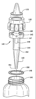
The bottle components shown in FIG. 27 share similarities with those
shown assembled previously in FIGS. 13-15. FIG. 27 shows an exploded view
of the components less the liquid container or bottle. A nipple 115 extends
out
from a collar 116 that secures to the bottle 1 as later also shown in Fig. 31.
Between the collar and the bottle, a vent insert 117 grasps the rim of the
bottle
1. The vent insert has a generally hollow cylindrical shape with a low height
perimeter wall 123. Across the diameter, the vent insert 117 has a lateral
vent
119 with a centered hole towards the direction of the bottle as shown in FIGS.
27A, 27B. The lateral vent has two opposed openings 118 that generally
communicate air between the bottle 1 and the atmosphere. The insert 117 has
a major lip 121 and a minor lip 122 concentric and slightly below the major
lip
121 as then shown in FIG. 27B. The vent insert 117 on its lateral surface has
the major lip 121. The major lip is also a hollow cylindrical shape
contiguous,
but of slightly lesser diameter, than the vent insert. In this manner, the
vent
insert can be applied in a tight seal within the rim of the bottle, during its
installation, and thereby prevent any leakage from the vent insert other than
the air venting desired from the structure of the insert and its applicable
usage
in a nursing bottle. The aperture providing air to the bottom of the bottle,
as at
114, for the contoured vent tube 113, shown here in the preferred embodiment
CA 02714171 2010-07-14
WO 2009/097078
PCT/US2009/000133
29
as conical though other shapes are possible as later shown in Fig 28. In
addition, the bottom of the vent tube typically ends, in this instance,
proximate
to the internal bottom of any container upon which the venting structure of
this
invention applies, regardless of whether it be the standard bottle, a wide rim
bottle, or the like. In an alternate embodiment, the aperture 114 has a
circumferential rib extending around it to stiffen the exit of the reservoir.
The
major lip has a circumferential bulge 124 of slightly larger diameter than the
= major lip. The bulge of the major lip seals the insert to the inner
diameter of
the bottle. The major lip has an outer diameter that of the inner diameter of
the
bottle. Depending from the lateral vent 119, the vent insert 117 has the minor
lip 122 as a hollow cylindrical shape of lesser diameter than the major lip.
The
minor lip 122 has a circumferential bulge 125 of slightly larger diameter than
the minor lip. The minor lip has an outer diameter of the inner diameter of
the
reservoir. The minor lip seals the reservoir 126 of the vent tube of the
present
invention to the vent insert 117.
The vent tube 113 has a reservoir 126 having a generally hollow
cylindrical shape with an open top 127 and a partially closed bottom 128. The
bottom is smoothed and rounded as it descends distally from the top. At the
center of the bottom 128, an aperture 129 provides passage to the vent tube
113 joined to the bottom. The vent tube then attains a hollow truncated
conical
shape With the larger diameter 130 located towards the reservoir 126 and the
narrow diameter 131 located distally.
Coaxial with the vent tube 113, the vent insert 117 has the distal insert
or internal vent tube 120 centered upon the hole in the lateral vent 119 and
perpendicular to the lateral vent 119 within the insert wall 123. The internal
vent tube 120 is a hollow cylinder of a length in excess of its diameter. The
internal vent tube 120 communicates air, but not feeding liquid in the current
invention, from the lateral vent 119 into the reservoir 126 of the vent tube
113.
CA 02714171 2010-07-14
WO 2009/097078
PCT/US2009/000133
FIG. 28 shows the vent tube 113 alone and having a large diameter
130 distal to and similar in diameter to the bottom 128 of the reservoir 126.
The vent tube 113 then tapers distally towards the narrow diameter 131. In the
preferred embodiment, the larger diameter 130 is approximately twice that of
5 the narrow diameter 131, in a minimum ratio of about 2:1.
FIG. 29 again shows the vent tube 113 but with the larger diameter 130
substantially less than previous embodiments. In this embodiment, the larger
diameter 130 attains at least one eighth more than the diameter of the narrow
diameter 131. Towards the narrow diameter 131, the vent tube 113 tapers
io distally as before. In this embodiment, the large diameter 130 is
greater than
the narrow diameter 131, in the range of approximately 3:1 to approximately
1:1 ratio, here shown in a ratio of about 1.1:1Ø
FIG. 30 shows an aberration that can possibly occur with a prior art
bottle in use by a=chewing infant with the bottle lowered below a horizontal
15 orientation for ready grasping by the infant. This bottle 1 has a
cylindrical tube
of constant diameter. With a down inclined bottle, the tube contacts the
feeding liquid. When the nipple is quickly compressed, as during chewing, the
compressed air above the liquid pressurizes the liquid briefly within the
container. The compressed air advances from the nipple through the vanes of
20 the insert and into the container, pressurizing it. The pressurized air
can
possibly force the liquid up into the prior art vent tube having straight and
constant diameter walls, but only when the inferior end of the venting tube is
submerged in the liquid. The liquid in the vent tube can possibly enter the
insert where it may possibly exit the bottle through the lateral ports of the
25 insert.
Fig. 30A then shows an embodiment of the present invention,
demonstrating that no leakage will occur in the conditions of a narrow neck
container, small volume of compressible air in the nipple, cylindrical vent
tube
CA 02714171 2010-07-14
WO 2009/097078
PCT/US2009/000133
31
terminating below the surface of the liquid, and the rapid compression of the
small volume nipple.
The conical vent tube of the present invention, shown in FIG. 31,
dissipates the feeding liquid induced into the vent tube. A conical shaped
tube
dissipates the pressure upon the liquid within the tube as the tube diameter
expands and the feeding liquid gently flows into the reservoir instead of the
lateral tube of the insert which rarely occurs in the prior art. Again, this
aberration in the prior art, except that of the inventors, can only occur with
a
combination of a cylindrical vent tube being submerged in the feeding liquid,
wide necked nipple having a large volume of compressible air, and the infant
quickly compressing the air in the large volume nipple. Then as later shown in
Fig. 31A, no leaks occur with a feeding container with a narrow or standard
neck bottle, small volume nipple, conical vent tube terminating below the
surface of the liquid, rapid compression of a small volume nipple.
Where a bottle 1 in FIG. 31 has a vent tube of a conical shape and
increasing diameter from the narrow distal end 131 to the wider proximal end
130, an infant chewing on the nipple 5 could pressurize the liquid 2 but the
increasing diameter of the conical vent tube increases the incremental volume
inside the tube and deters feeding liquid 2 from entering the insert 119, as
shown in Fig. 30, and leaking out of the collar 6. The increasing conical vent
tube diameter limits any pressure increases within the bottle 1 and thus the
possibility of leaks from the bottle are prevented by the present invention.
Thus, the propulsion of liquid to the insert cannot occur in a narrow neck
bottle, see Figs. 30A, 31A, with either a cylindrical or conical venting tube
due
to the smaller amount of compressible air in the smaller nipple. The movement
of liquid into the insert in the wide neck bottle with the larger diameter
nipple,
that is a greater volume of compressible air, can only occur, rarely, when a
cylindrical venting tube is used and is submerged in the liquid while in the
resting position and only with rapid compression of the wide necked nipple as
CA 02714171 2010-07-14
WO 2009/097078
PCT/US2009/000133
32
in Fig. 30. When a conical shaped venting tube is used at any time, as in
Figs.
31, 31A, or when a narrow, or standard, bottle diameter is used, as in Figs.
30AA, 31A, this phenomenon can never occur.
The bottle components shown in FIG. 32 share similarities with those
shown previously in FIG. 27. This embodiment of the invention appears as an
exploded view of the Components less the liquid container or bottle. A nipple
115 extends out from a collar 116 that secures to the bottle 1, as shown
earlier
in Fig. 31. Between the collar and the bottle, a vent insert 117 grasps the
rim
of the bottle 1. The vent insert has a generally hollow cylindrical shape with
a
io low height perimeter wall. Across the diameter, the vent insert 117 has
a
lateral vent 119 with a centered hole towards the bottle. The lateral vent has
two opposed openings that generally communicate air between the bottle 1
and the atmosphere. The insert 117 has the lips and other features thereof as
previously described. In this manner, the vent insert can be applied in a
tight
seal within the rim of the bottle as its first seal, with the second seal
achieved
by mating on the top edge of the feeding container, during its installation,
and
thereby preventing any leakage of liquid from the vent insert, however, the
desirable air venting from the structure of the insert and its applicability
and
usage in a nursing container is preserved. The internal vent tube 120
descends from the vent insert 117 into the reservoir 126 when the present
invention is assembled. The internal vent tube 120 is a hollow cylinder of a
length in excess of its diameter. The internal vent tube 120 communicates air,
but not feeding liquid in the current invention, from the lateral vent 119
into the
reservoir 126 of the vent tube 132. The internal vent tube 120 is generally
parallel to the longitudinal axis of the reservoir.
The vent tube 132 has a reservoir 126 with a generally hollow
cylindrical shape with an open top 127 and a partially closed bottom 128 as
before. The bottom is smoothed and rounded as it descends distally from the
top. At the center of the bottom 128, an aperture 129 provides passage to the
CA 02714171 2010-07-14
WO 2009/097078
PCT/US2009/000133
33
vent tube 132 joined to the bottom. The vent tube then attains a hollow
truncated conical shape at an angle to the plane of the aperture. Generally
the
vent tube is bent or canted unlike the previous embodiments. The cant of the
vent tube matches the angle of the nursing bottle later shown in FIG. 35. The
vent tube 132 is also at an angle to the internal vent tube 120. The larger
diameter 133 of the vent tube is located towards the reservoir 126 and the
narrow diameter 134 located distal from the reservoir. The vent tube 132 has
an aperture 135 at the narrower diameter through which air vents to the
bottom of the bottle.
FIG. 33 shows the vent tube 132 separated from the other components
of the nursing bottle. The vent tube 132 has a large diameter 133 proximate to
and similar in diameter to the bottom 128 of the reservoir 126. The vent tube
132 then tapers distally towards the narrow diameter 134 and outwards and
away from the centerline or longitudinal axis of the reservoir. In the
preferred
embodiment, the vent tube has an angle of about approximately 15 to about
approximately 25 degrees.
FIG. 34 shows the vent tube 132 again without the vent insert and other
components of the nursing bottle. In this embodiment, the vent tube has a
cant as before but has a spout 133A that connects to the reservoir. The spout
is generally a hollow cylinder and of similar diameter to the aperture 129 of
the
reservoir. The spout is also coaxial with the reservoir and spaces apart the
larger diameter 133 of the vent tube from the reservoir. The spacing apart
aids
in fitting the canted vent tube within an angled nursing bottle. As before,
towards the narrow diameter 134, the vent tube 132 tapers distally and angles
outward from the centerline. In this embodiment, the large diameter 133 is
greater than the narrow diameter 134, generally in the range of 2:1 to 3:1.
The tapered vent tube of an embodiment, shown in FIG. 35, dissipates
the pressure of the feeding liquid induced into the vent tube of an angled
bottle. A conical shaped tube at an angle to the centerline of the bottle
CA 02714171 2010-07-14
WO 2009/097078
PCT/US2009/000133
34
dissipates the pressure upon the liquid within the tube as the tube diameter
expands and the feeding liquid gently flows into the reservoir instead of
possibly flowing into the venting tube of the insert. The cant of the vent
tube
also keeps it spaced apart from the wall of the bottle. The angle of the
container or bottle eases grasping of the bottle by an infant with developing
motor skills and reminds the caregiver to keep the head of the infant in a
more
raised position. Where an angled bottle 1' in FIG. 35 has a vent tube 132
including a conical shape and increasing diameter from the narrow distal end
134 to the wider proximal end 133, an infant chewing on the nipple 5 may
io cause pressure to be applied to the liquid 2 but the increasing diameter
of the
vent tube increases the incremental volume inside the tube and deters feeding
liquid 2 from possibly entering the insert 119, as shown in Fig. 30, and
leaking
out of the collar 6. The increasing vent tube diameter dissipates any pressure
increases occurring within bottle 1' when it is a wide neck bottle utilizing
larger
nipples that have a greater volume of compressible air, and thus the
possibilities of leaks are prevented by the present invention.
Another embodiment appears upright in FIG. 36. The angled bottle 1'
has a nipple 5 secured upon the bottle with a collar 6. The reservoir 126, as
seen in Fig. 32, connects to the vent insert 120 opposite from the nipple. The
canted tube 132 used in this embodiment descends from the upper portion of
the bottle 1' into the feeding liquid 2 here shown in the lower portion of the
bottle. This bottle has an angle that extends the nipple away from the
centerline of the bottle. The extended nipple and connecting parts move the
center of gravity of the bottle away from the center of the bottle. If feeding
liquid rises to the upper portion of the bottle, the center of gravity of the
bottle
moves in the horizontal direction of the nipple. With the center of gravity
moved far enough outwards, the bottle 1' has a risk of tipping. The present
invention has a foot like stabilizing base 136 joined to the bottom of the
bottle
that extends also in the horizontal direction of the nipple. The stabilizing
base
CA 02714171 2010-07-14
WO 2009/097078
PCT/US2009/000133
extends the tipping point from the edge of the bottle to the edge of the
stabilizing base. An extending tipping point reduces the risk of a full or
nearly
full angled bottle 1' tipping over when placed in an upright position.
FIG. 37 shows the angled bottle 1' from the bottom with the stabilizing
5 base 136 installed. The stabilizing base 136 joins to the bottom of the
bottle 1'
and provides a flat and continuous surface upon which the bottle 1' stands. In
this embodiment, the stabilizing base is crescent shaped with the widest part
of the crescent located upon a line between the center of the bottle, shown by
the narrow diameter 135 of the vent tube, and the nipple shown obscured by
10 the collar 6. The stabilizing base tapers in width until the stabilizing
base
approaches the bottle tangentially at two opposed points. The stabilizing base
136 itself has a generally flat planar shape with two curved, crescent shaped
edges, an outer convex edge and an inner concave edge. The concave edge
of the stabilizing base joins to the bottom of the bottle 1' as previously
15 described.
The fully vented wide rim bottle with a single piece insert 140,
combining the reservoir and venting tube, is shown in FIG. 38. In this
exploded
view, the present invention releases feeding liquid to an infant with any
vacuum in the container being eliminated through the single piece insert 140,
20 particularly the venting tube portion 143 later described, to the
atmosphere. As
before, the present invention has a container, generally cylindrical but of a
length approximately one third more than the diameter. This container is
designed for holding approximately 60 ml or 2 fl. oz. of feeding liquid, a
suitable volume for a small infant. This container volume may easily be
25 increased or decreased for convenience or preference. The container has
a
neck 141 upon one end. The container of feeding liquid has a generally
cylindrical shape and is approximately 130 mm in height, 50 mm in diameter,
and has a uniform wall thickness of approximately 3 mm. The superior end, or
neck, of the bottle has circumferential external threads that cooperate with a
CA 02714171 2010-07-14
WO 2009/097078
PCT/US2009/000133
36
collar 116. The collar, as before, is a hollow cylinder with flutes upon the
edge
for grasping. One end of the cylinder is partially closed with a flange that
has a
central opening for admitting a nipple 115. The nipple has a distal end with a
hole for releasing feeding liquid.
Generally, a feeding nipple is approximately 20 mm in diameter and 40
mm in height. The nipple has a small, precisely manufactured hole in its
distal
end to allow for the release of feeding liquid from the container, through the
nipple. The inferior surface of the nipple is a generally flat round flange so
as
to mate in a flush manner with the superior surface of the insert portion that
io itself
rests upon the neck of the container. In one embodiment, the releasing
device for the fluid container is shaped as a nipple, the superior aspect of
the
nipple has a generally cylindrical shape, approximately 14 mm in diameter and
21 mm in height. A circular collar having internal female threads holds the
nipple, or other device, in place upon the insert which rests upon the neck of
the container as its threads engage the male threads 141 upon the neck.
When the collar is turned completely upon the neck, the nipple or other
device, is firmly secured to the superior aspect of the insert portion.
Between the collar and the container, the present invention has the
single piece insert with its reservoir and conical venting tube, generally
coaxial
with the center of the container. The single piece venting structure begins
with
a conical venting tube 143 that opens at the internal bottom of the container.
The venting tube is hollow and has a conical shape. The venting tube typically
has a length of at least two diameters and joins to a reservoir 144. The
reservoir has a constant diameter that is larger than that of the venting
tube.
= 25 The reservoir is at least two diameters in length and has the general
form of a
hollow cylinder. The reservoir has a volume with a volumetric center, an upper
end affixed to the insert and an opposite lower end from which the venting
tube extends. The upper end of the reservoir joins to an insert portion 145
that
spans the neck of the container. The lower end joins to the venting tube
CA 02714171 2010-07-14
WO 2009/097078
PCT/US2009/000133
37
previously described. In addition, a vent 148 proceeds inferiorly from the
horizontal aperture of the insert and terminates in the volumetric center of
the
reservoir.
The venting tube has a hollow tapering shape, as at 143, with the
smaller diameter 151 at the internal bottom of the container and a larger
diameter 152 where the venting tube joins to the reservoir.
The insert portion has sufficient diameter to reach the neck and to
cover the circumference of the neck. A rib 146 spans across the diameter of
the insert portion and has two ends that connect with the annular, or ring
like,
io insert portion. An aperture 147 forms the aperture portion of the insert
of the
present invention. Later shown in Fig. 39C, the aperture portion has a
continuous aperture that has one end terminating to the outside air and the
opposite end terminating in the volumetric center of the reservoir. Upon one
end, a horizontal aperture 147 extends from the outer edge of the insert
portion and through the rib to the center of the rib. At the center of the
rib, the
horizontal aperture connects to a vent 148. The vent extends below the rib,
perpendicular to the insert portion, and into the reservoir. The insert vent
is
generally a hollow cylinder of lesser diameter than the reservoir. The vent
extends to approximately half of the length of the reservoir. Preferably, the
horizontal aperture 147 extends across the entire diameter of the insert
portion
and again meets the vertical aperture 149 in the center of the horizontal
section of the aperture, such that a T shaped connection of apertures is
formed.
Between the insert portion and the neck, the present invention includes
a gasket 149. The gasket is generally round, planar in shape, and has a
central opening 150 to admit the reservoir through the neck. The gasket
compresses and fills voids between the neck 141 and the insert portion 145
when the collar 116 secures the insert portion and the nipple upon the neck.
Alternatively, the gasket is removed from the invention.
CA 02714171 2010-07-14
WO 2009/097078
PCT/US2009/000133
38
The venting mechanism has a component, the insert portion 145, that
rests upon the gasket atop neck of the bottle, or container, a reservoir 144
and
a conical venting tube 143 generally perpendicular and centered below the
insert and reservoir portions. The insert portion, reservoir, and the conical
venting tube are combined into a single piece insert, generally of T shape
shown in a detailed view in FIG. 39A.The insert portion 145 has a generally
round shape with a rib (not shown) spanning across the insert portion and a
vent 148 depending below the rib. The inferior aspect of the vent 148
terminates in the volumetric center of a cylindrical reservoir 144. The
reservoir
io is
preferably formed as a single piece including the venting tube 143, vent
148, and the insert portion 145. Alternatively, the reservoir is joined to the
insert portion by sonic welding, thermal welding, solvent or chemical welding,
spin, or rotational welding, friction or snap fitting, and like means of
securing
the insert portion to the reservoir thus forming a single piece venting
mechanism. Extending toward the bottom of the container from the lower end
of the reservoir 144, the conical venting tube 143 terminates slightly above
the
interior bottom of the container and has a conical shape through its length.
Alternatively, a differently shaped tube may be used that also terminates near
the bottom of the container.
Turning the single piece vent tube provides Fig. 39B. Here the insert
portion has a generally round shape with a horizontal aperture147 upon the
circumference that continues through a rib 146, also shown in Fig. 39D,
across the diameter of the insert portion. Generally centered in the rib, a
hole
149 communicates with the horizontal aperture and the vent 148 connects
below the rib at the hole. The reservoir 144 itself also connects to the
central
portion of the rib, outwards of the vent. The flow path for air through the
single
piece vent tube is shown in Fig. 39C. The insert portion has a horizontal
aperture147 that opens at the circumference of the insert portion. The
horizontal aperture continues through the rib 146 to the center where it
CA 02714171 2010-07-14
WO 2009/097078
PCT/US2009/000133
39
communicates to a hole 149 centered in the lower surface of the rib where the
vent 148 connects.
Viewing the single piece vent from above in Fig. 39D, the insert portion
is shown where the insert portion 145 has a generally round, annular shape,
with a central rib 146 spanning the diameter of the insert portion. The rib
has a
horizontal aperture 147 as before that opens upon the edge of the insert
portion for communicating with the atmosphere. The horizontal aperture
continues through the rib along a radius of the insert portion, here shown in
phantom. The horizontal aperture connects to a hole 149 partially through the
io thickness of the central portion 150 of the rib and then to the vent
148.
Having described the components and arrangement of them, the
present invention is used by an infant in cooperation with a caregiver as
=shown in Fig 40. With the container in a feeding position, raised to an angle
above the horizontal, venting air flows through the threads of the neck and
into
the horizontal aperture, through the hole in the rib and into the vent, down
into
the reservoir, and then into the adjoining conical venting tube where it exits
at
the bottom of the container. The entrance of air through the venting tube
eliminates the formation of a vacuum within the container and its associated
adverse transfer into an infant's oral cavity and associated structures.
The venting mechanism of the present invention permits an
uninterrupted flow of air into the container, thereby eliminating any vacuum
formation in the container. This airflow occurs without mixing any air into
the
feeding liquid or without any feeding liquid escaping, that is leaking, from
the
container. Additionally, when the container is held in an inverted feeding
position, the feeding liquid now flows through the openings in the insert
portion
between the annular edge and the rib, and then into the nipple or other liquid
dispensing attachment. Furthermore, the liquid in the tapering venting tube
flows quickly and gently into the reservoir. The liquid becomes trapped within
the reservoir below the volumetric center and the inferior end of the venting
CA 02714171 2010-07-14
WO 2009/097078
PCT/US2009/000133
tube. Any air that remains in the venting system readily enters into the
container bottom similar to the air entering the venting mechanism through the
neck of the container.
When the container is returned to a vertical position, as when the neck
5 is
deviated upwardly, the liquid trapped in the reservoir now flows down into
the venting tube to pool with the remaining liquid in the container, again,
without mixing air into the liquid or liquid leaking from the container. In
the
preferred embodiment of the venting tube, the superior end increases the
effective volume of the reservoir.
io Returning
to an inverted position, the tapered embodiment of the
venting tube allows liquid to flow quickly and easily into the reservoir and
allows air initially within the reservoir to quickly enter the bottom space of
the
container. In a vertical position, the tapered venting tube increases the
overall
volume capacity of the reservoir.
15 The usage
of the present invention is similar to that of the inventors'
previously patented feeding containers. The present venting mechanism, here
a single piece, is inserted, venting tube first, into the container where the
insert
portion rests upon a gasket upon the neck. Alternatively, no gasket is
present.
Upon the insert, a feeding nipple is generally placed though other devices may
20 attach as
well. The feeding nipple is held firmly, to the neck via the insert and
by a collar threadily engaging the neck. The nipple has an aperture, or hole,
for release of feeding liquid, with the size of the aperture determining the
rate
of flow of the liquid from the container, where a larger hole leads to faster
flow
of liquid.
25 The
present invention has a unique simultaneous operation of the
container with both air and feeding liquid. Airflow proceeds around the
threads
of the neck of the fluid filled container, through the insert portion, into
the vent
tube depending from the center of the insert portion, into the cylindrically
shaped reservoir, then into the preferred conically shaped venting tube, or
CA 02714171 2010-07-14
WO 2009/097078
PCT/US2009/000133
41
alternatively a cylindrically shaped venting tube, and exits at the internal
bottom of the container. This airflow eliminates contamination of the liquid
within the container with air. The conical shape of the venting tube of the
reservoir eases the release of air from the vent tube into the inferior aspect
of
the feeding container when inverted during feeding time.
When inverted, the feeding liquid in the reservoir venting tube, now
flows gently into the large diameter portion of the reservoir and remains
there
until the bottle, or container, is again placed upright when the liquid exits
the
reservoir downward and pools with,the remainder of liquid within the bottle.
io The reservoir prevents the liquid from reaching the vent tube depending
from
the insert portion, located in the volumetric center of the reservoir, by
several
mechanisms when the bottle is inverted. First, the reservoir, with its conical
venting tube, reduces the force of the liquid approaching the vent tube of the
insert portion. Second, the preferred embodiment of the conical venting tube
allows the feeding liquid therein to move more quickly and easily into the
reservoir. During such movement, the air in the conical venting tube more
easily exits to the inferior, or bottom of the bottle. Third, the reservoir
increases its effective volume as the taper of the preferred embodiment of the
venting tube temporarily stores feeding liquid.
These mechanisms allow for complete and continuous venting of the
container at all times without contamination of the liquid with air and also
prevents any leakage. The container accommodates the liquid that remains in
different parts of the venting mechanism at different times during usage.
These mechanisms allow the present invention to function as a vent and
accommodate fluid, separate air and fluid at all times, and prevent leaks from
the container when in any position.
From the aforementioned description, a fully vented wide rim, or other
diameter, nursing bottle with a single piece insert has been described. This
nursing bottle is uniquely capable of eliminating negative pressure
CA 02714171 2010-07-14
WO 2009/097078
PCT/US2009/000133
42
continuously and automatically in a bottle or container. This nursing bottle
and
its various components may be manufactured from many different materials
including but not limited to polymers, low density polyethylene, high density
polyethylene, polypropylene, glass, nylon, ferrous and non-ferrous metals,
their alloys, silicone, and composites. For an example, the feeding container
may be made of polypropylene, polycarbonate, polyethylene, or other suitable
material. And, the collar for fastening the nipple upon the feeding container
may be made of polyethylene, polypropylene, or other material, and the
adjacent feeding nipple is preferably made of silicone, or another material.
io Variations or modifications to the subject matter of this invention may
occur to those skilled in the art upon reviewing the development as described
herein. Such variations, if within the scope of this development, are intended
to be encompassed within the principles of this invention, as explained
herein.
The descriptions of the preferred embodiment, in addition to the depiction
is within the drawings, are set forth for illustrative purposes only.